CHRYSLER CARAVAN 2005 Service Manual
Manufacturer: CHRYSLER, Model Year: 2005, Model line: CARAVAN, Model: CHRYSLER CARAVAN 2005Pages: 2339, PDF Size: 59.69 MB
Page 101 of 2339
NOTE: Care must be taken not to separate the inner
C/V joint during this operation. Do not allow half shaft
to hang by inner C/V joint after removing outer C/V
Joint from the hub/bearing assembly in steering
knuckle, end of half shaft must be supported.
(11) Pull steering knuckle assembly down and
away from the outer C/V joint of the half shaft
assembly while pulling the joint out of the hub bear-
ing.
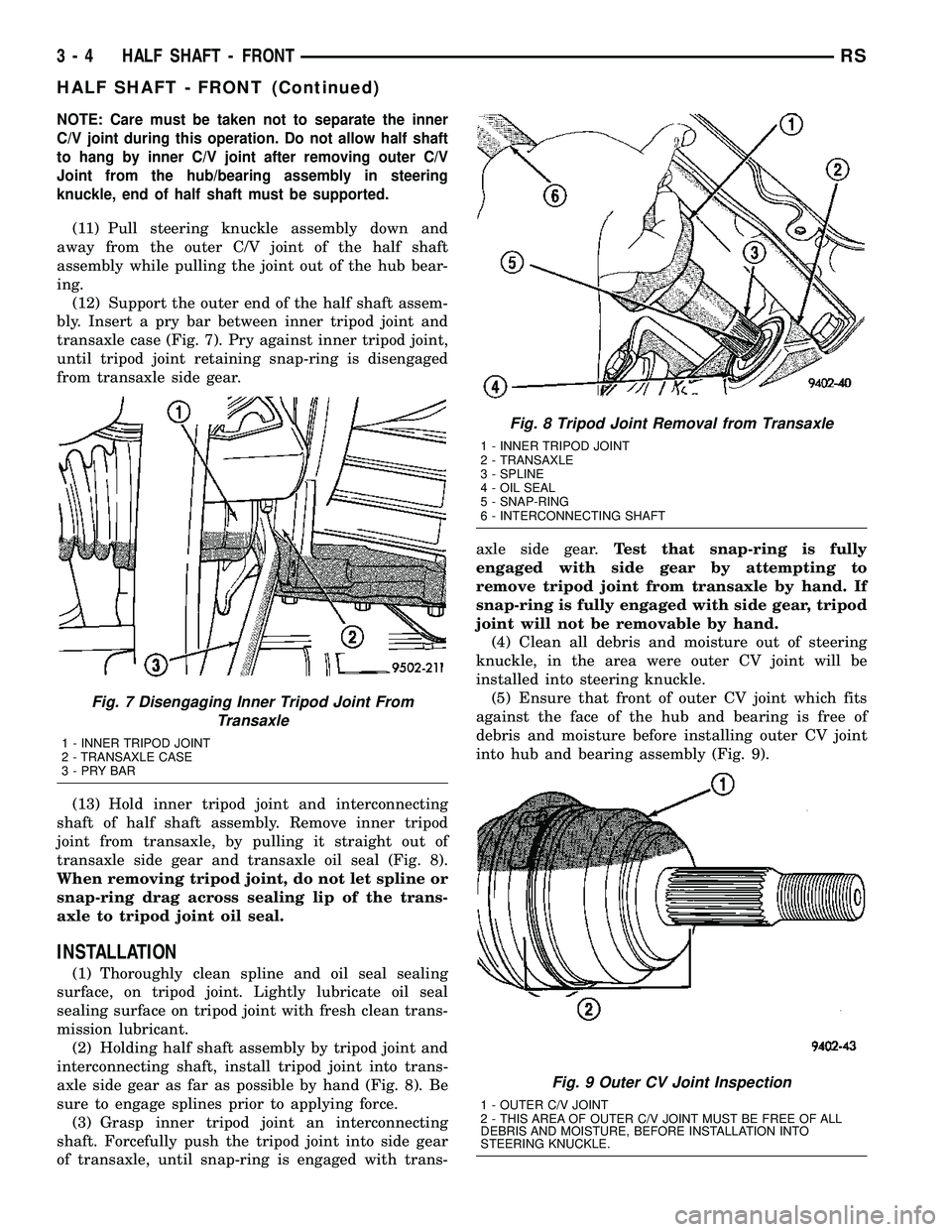
(12) Support the outer end of the half shaft assem-
bly. Insert a pry bar between inner tripod joint and
transaxle case (Fig. 7). Pry against inner tripod joint,
until tripod joint retaining snap-ring is disengaged
from transaxle side gear.
(13) Hold inner tripod joint and interconnecting
shaft of half shaft assembly. Remove inner tripod
joint from transaxle, by pulling it straight out of
transaxle side gear and transaxle oil seal (Fig. 8).
When removing tripod joint, do not let spline or
snap-ring drag across sealing lip of the trans-
axle to tripod joint oil seal.
INSTALLATION
(1) Thoroughly clean spline and oil seal sealing
surface, on tripod joint. Lightly lubricate oil seal
sealing surface on tripod joint with fresh clean trans-
mission lubricant.
(2) Holding half shaft assembly by tripod joint and
interconnecting shaft, install tripod joint into trans-
axle side gear as far as possible by hand (Fig. 8). Be
sure to engage splines prior to applying force.
(3) Grasp inner tripod joint an interconnecting
shaft. Forcefully push the tripod joint into side gear
of transaxle, until snap-ring is engaged with trans-axle side gear.Test that snap-ring is fully
engaged with side gear by attempting to
remove tripod joint from transaxle by hand. If
snap-ring is fully engaged with side gear, tripod
joint will not be removable by hand.
(4) Clean all debris and moisture out of steering
knuckle, in the area were outer CV joint will be
installed into steering knuckle.
(5) Ensure that front of outer CV joint which fits
against the face of the hub and bearing is free of
debris and moisture before installing outer CV joint
into hub and bearing assembly (Fig. 9).
Fig. 7 Disengaging Inner Tripod Joint From
Transaxle
1 - INNER TRIPOD JOINT
2 - TRANSAXLE CASE
3-PRYBAR
Fig. 8 Tripod Joint Removal from Transaxle
1 - INNER TRIPOD JOINT
2 - TRANSAXLE
3 - SPLINE
4 - OIL SEAL
5 - SNAP-RING
6 - INTERCONNECTING SHAFT
Fig. 9 Outer CV Joint Inspection
1 - OUTER C/V JOINT
2 - THIS AREA OF OUTER C/V JOINT MUST BE FREE OF ALL
DEBRIS AND MOISTURE, BEFORE INSTALLATION INTO
STEERING KNUCKLE.
3 - 4 HALF SHAFT - FRONTRS
HALF SHAFT - FRONT (Continued)
Page 102 of 2339
(6) Slide half shaft back into front hub and bear-
ing assembly.
CAUTION: The steering knuckle to strut assembly
attaching bolts are serrated and must not be turned
during installation. Install nuts while holding bolts
stationary in the steering knuckle.
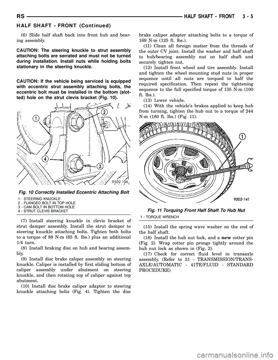
CAUTION: If the vehicle being serviced is equipped
with eccentric strut assembly attaching bolts, the
eccentric bolt must be installed in the bottom (slot-
ted) hole on the strut clevis bracket (Fig. 10).
(7) Install steering knuckle in clevis bracket of
strut damper assembly. Install the strut damper to
steering knuckle attaching bolts. Tighten both bolts
to a torque of 88 N´m (65 ft. lbs.) plus an additional
1/4 turn.
(8) Install braking disc on hub and bearing assem-
bly.
(9) Install disc brake caliper assembly on steering
knuckle. Caliper is installed by first sliding bottom of
caliper assembly under abutment on steering
knuckle, and then rotating top of caliper against top
abutment.
(10) Install disc brake caliper adapter to steering
knuckle attaching bolts (Fig. 4). Tighten the discbrake caliper adapter attaching bolts to a torque of
169 N´m (125 ft. lbs.).
(11) Clean all foreign matter from the threads of
the outer CV joint. Install the washer and half shaft
to hub/bearing assembly nut on half shaft and
securely tighten nut.
(12) Install front wheel and tire assembly. Install
and tighten the wheel mounting stud nuts in proper
sequence until all nuts are torqued to half the
required specification. Then repeat the tightening
sequence to the full specified torque of 135 N´m (100
ft. lbs.).
(13) Lower vehicle.
(14) With the vehicle's brakes applied to keep hub
from turning, tighten the hub nut to a torque of 244
N´m (180 ft. lbs.) (Fig. 11).
(15) Install the spring wave washer on the end of
the half shaft.
(16) Install the hub nut lock, and anewcotter pin
(Fig. 2). Wrap cotter pin prongs tightly around the
hub nut lock as shown in (Fig. 2).
(17) Check for correct fluid level in transaxle
assembly. (Refer to 21 - TRANSMISSION/TRANS-
AXLE/AUTOMATIC - 41TE/FLUID - STANDARD
PROCEDURE)
Fig. 10 Correctly Installed Eccentric Attaching Bolt
1 - STEERING KNUCKLE
2 - FLANGED BOLT IN TOP HOLE
3 - CAM BOLT IN BOTTOM HOLE
4 - STRUT CLEVIS BRACKET
Fig. 11 Torquing Front Half Shaft To Hub Nut
1 - TORQUE WRENCH
RSHALF SHAFT - FRONT3-5
HALF SHAFT - FRONT (Continued)
Page 103 of 2339
SPECIFICATIONS - HALF SHAFT - FRONT
TORQUE SPECIFICATIONS
DESCRIPTION N´m Ft. Lbs. In. Lbs.
Bolts, Caliper Adapter to
Knuckle169 125 -
Nut, Hub 244 180 -
Nuts, Front Wheel Lug 135 100 -
Nut, Tie Rod End to
Knuckle75 55 -
Nut, Strut Clevis to
Knuckle81 +90É 60 +90É -
CV BOOT - INNER
REMOVAL
(1) Remove the half shaft requiring boot replace-
ment from the vehicle. (Refer to 3 - DIFFERENTIAL
& DRIVELINE/HALF SHAFT - REMOVAL)
(2) Remove large boot clamp which retains inner
tripod joint sealing boot to tripod joint housing and
discard.
(3) Remove small clamp which retains inner tripod
joint sealing boot to interconnecting shaft and dis-
card.
(4) Remove the sealing boot from the tripod hous-
ing and slide it down the interconnecting shaft.
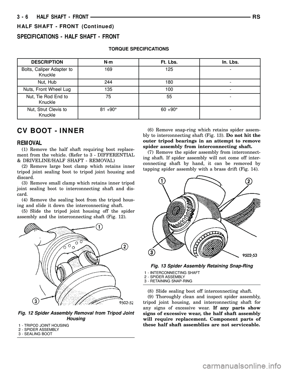
(5) Slide the tripod joint housing off the spider
assembly and the interconnecting shaft (Fig. 12).(6) Remove snap-ring which retains spider assem-
bly to interconnecting shaft (Fig. 13).Do not hit the
outer tripod bearings in an attempt to remove
spider assembly from interconnecting shaft.
(7) Remove the spider assembly from interconnect-
ing shaft. If spider assembly will not come off inter-
connecting shaft by hand, it can be removed by
tapping spider assembly with a brass drift (Fig. 14).
(8) Slide sealing boot off interconnecting shaft.
(9) Thoroughly clean and inspect spider assembly,
tripod joint housing, and interconnecting shaft for
any signs of excessive wear.If any parts show
signs of excessive wear, the half shaft assembly
will require replacement. Component parts of
these half shaft assemblies are not serviceable.
Fig. 12 Spider Assembly Removal from Tripod Joint
Housing
1 - TRIPOD JOINT HOUSING
2 - SPIDER ASSEMBLY
3 - SEALING BOOT
Fig. 13 Spider Assembly Retaining Snap-Ring
1 - INTERCONNECTING SHAFT
2 - SPIDER ASSEMBLY
3 - RETAINING SNAP-RING
3 - 6 HALF SHAFT - FRONTRS
HALF SHAFT - FRONT (Continued)
Page 104 of 2339
INSTALLATION
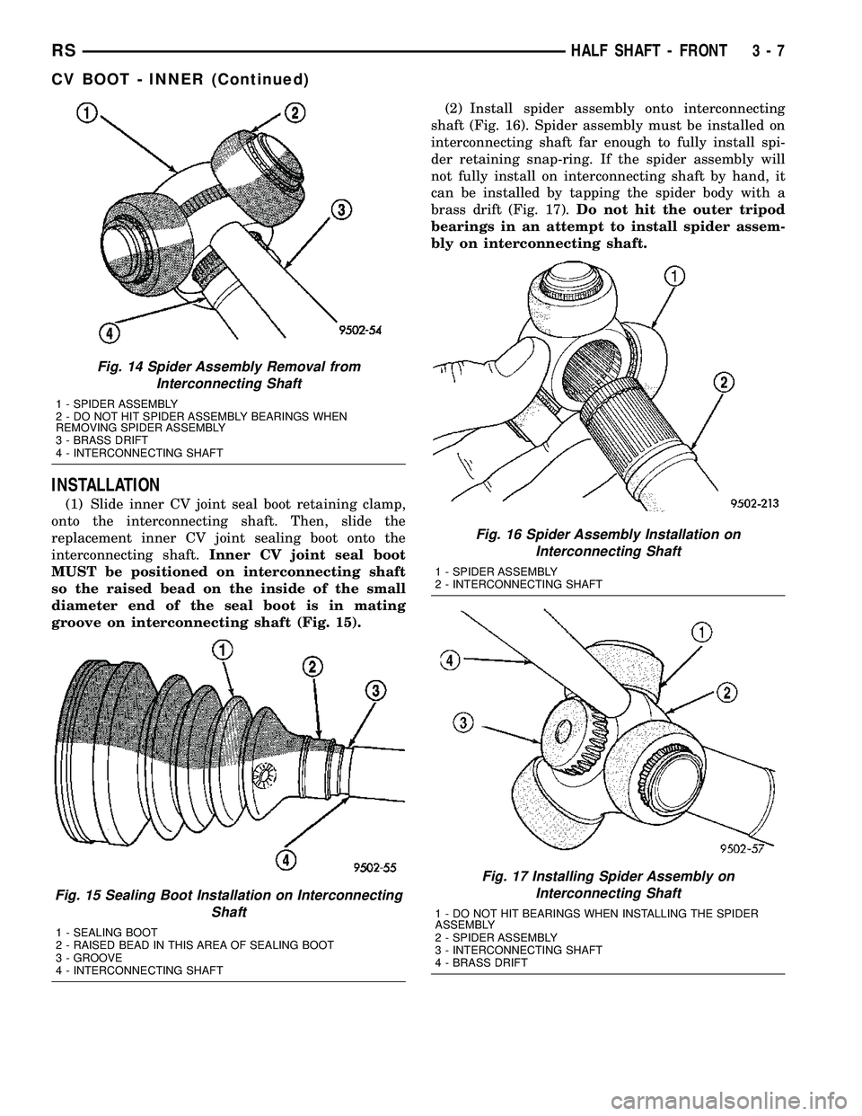
(1) Slide inner CV joint seal boot retaining clamp,
onto the interconnecting shaft. Then, slide the
replacement inner CV joint sealing boot onto the
interconnecting shaft.Inner CV joint seal boot
MUST be positioned on interconnecting shaft
so the raised bead on the inside of the small
diameter end of the seal boot is in mating
groove on interconnecting shaft (Fig. 15).(2) Install spider assembly onto interconnecting
shaft (Fig. 16). Spider assembly must be installed on
interconnecting shaft far enough to fully install spi-
der retaining snap-ring. If the spider assembly will
not fully install on interconnecting shaft by hand, it
can be installed by tapping the spider body with a
brass drift (Fig. 17).Do not hit the outer tripod
bearings in an attempt to install spider assem-
bly on interconnecting shaft.
Fig. 14 Spider Assembly Removal from
Interconnecting Shaft
1 - SPIDER ASSEMBLY
2 - DO NOT HIT SPIDER ASSEMBLY BEARINGS WHEN
REMOVING SPIDER ASSEMBLY
3 - BRASS DRIFT
4 - INTERCONNECTING SHAFT
Fig. 15 Sealing Boot Installation on Interconnecting
Shaft
1 - SEALING BOOT
2 - RAISED BEAD IN THIS AREA OF SEALING BOOT
3 - GROOVE
4 - INTERCONNECTING SHAFT
Fig. 16 Spider Assembly Installation on
Interconnecting Shaft
1 - SPIDER ASSEMBLY
2 - INTERCONNECTING SHAFT
Fig. 17 Installing Spider Assembly on
Interconnecting Shaft
1 - DO NOT HIT BEARINGS WHEN INSTALLING THE SPIDER
ASSEMBLY
2 - SPIDER ASSEMBLY
3 - INTERCONNECTING SHAFT
4 - BRASS DRIFT
RSHALF SHAFT - FRONT3-7
CV BOOT - INNER (Continued)
Page 105 of 2339
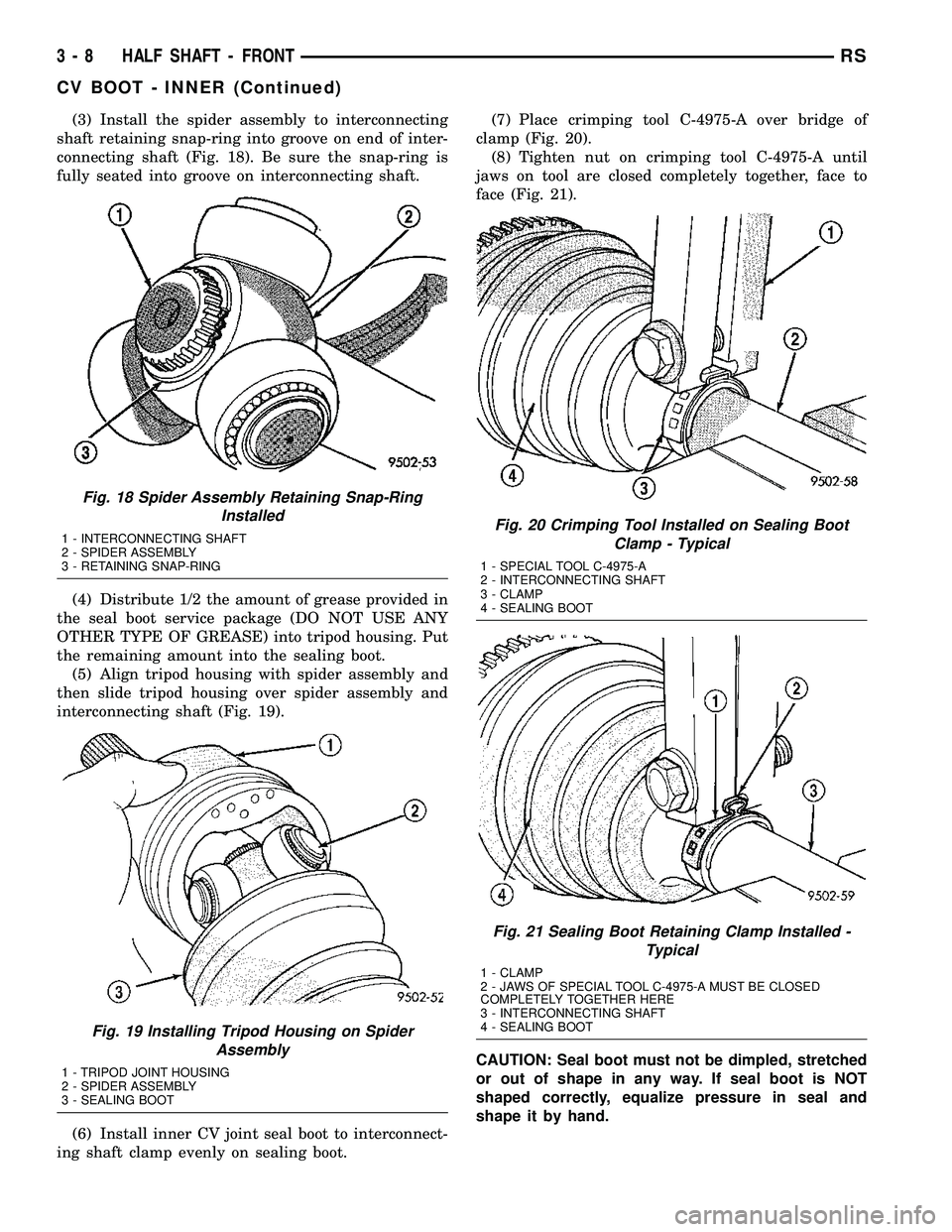
(3) Install the spider assembly to interconnecting
shaft retaining snap-ring into groove on end of inter-
connecting shaft (Fig. 18). Be sure the snap-ring is
fully seated into groove on interconnecting shaft.
(4) Distribute 1/2 the amount of grease provided in
the seal boot service package (DO NOT USE ANY
OTHER TYPE OF GREASE) into tripod housing. Put
the remaining amount into the sealing boot.
(5) Align tripod housing with spider assembly and
then slide tripod housing over spider assembly and
interconnecting shaft (Fig. 19).
(6) Install inner CV joint seal boot to interconnect-
ing shaft clamp evenly on sealing boot.(7) Place crimping tool C-4975-A over bridge of
clamp (Fig. 20).
(8) Tighten nut on crimping tool C-4975-A until
jaws on tool are closed completely together, face to
face (Fig. 21).
CAUTION: Seal boot must not be dimpled, stretched
or out of shape in any way. If seal boot is NOT
shaped correctly, equalize pressure in seal and
shape it by hand.
Fig. 18 Spider Assembly Retaining Snap-Ring
Installed
1 - INTERCONNECTING SHAFT
2 - SPIDER ASSEMBLY
3 - RETAINING SNAP-RING
Fig. 19 Installing Tripod Housing on Spider
Assembly
1 - TRIPOD JOINT HOUSING
2 - SPIDER ASSEMBLY
3 - SEALING BOOT
Fig. 20 Crimping Tool Installed on Sealing Boot
Clamp - Typical
1 - SPECIAL TOOL C-4975-A
2 - INTERCONNECTING SHAFT
3 - CLAMP
4 - SEALING BOOT
Fig. 21 Sealing Boot Retaining Clamp Installed -
Typical
1 - CLAMP
2 - JAWS OF SPECIAL TOOL C-4975-A MUST BE CLOSED
COMPLETELY TOGETHER HERE
3 - INTERCONNECTING SHAFT
4 - SEALING BOOT
3 - 8 HALF SHAFT - FRONTRS
CV BOOT - INNER (Continued)
Page 106 of 2339
(9) Position sealing boot into the tripod housing
retaining groove. Install seal boot retaining clamp
evenly on sealing boot.
(10) Position trilobal boot to interface with the tri-
pod housing. The lobes of the boot must be properly
aligned with the recess's of the tripod housing.
CAUTION: The following positioning procedure deter-
mines the correct air pressure inside the inner CV
joint assembly prior to clamping the sealing boot to
inner CV joint housing. If this procedure is not done
prior to clamping sealing boot to CV joint housing
sealing boot durability can be adversely affected.
CAUTION: When venting the inner CV joint assembly,
use care so that the inner CV sealing boot does not
get punctured, or in any other way damaged. If sealing
boot is punctured, or damaged in any way while being
vented, the sealing boot can not be used.
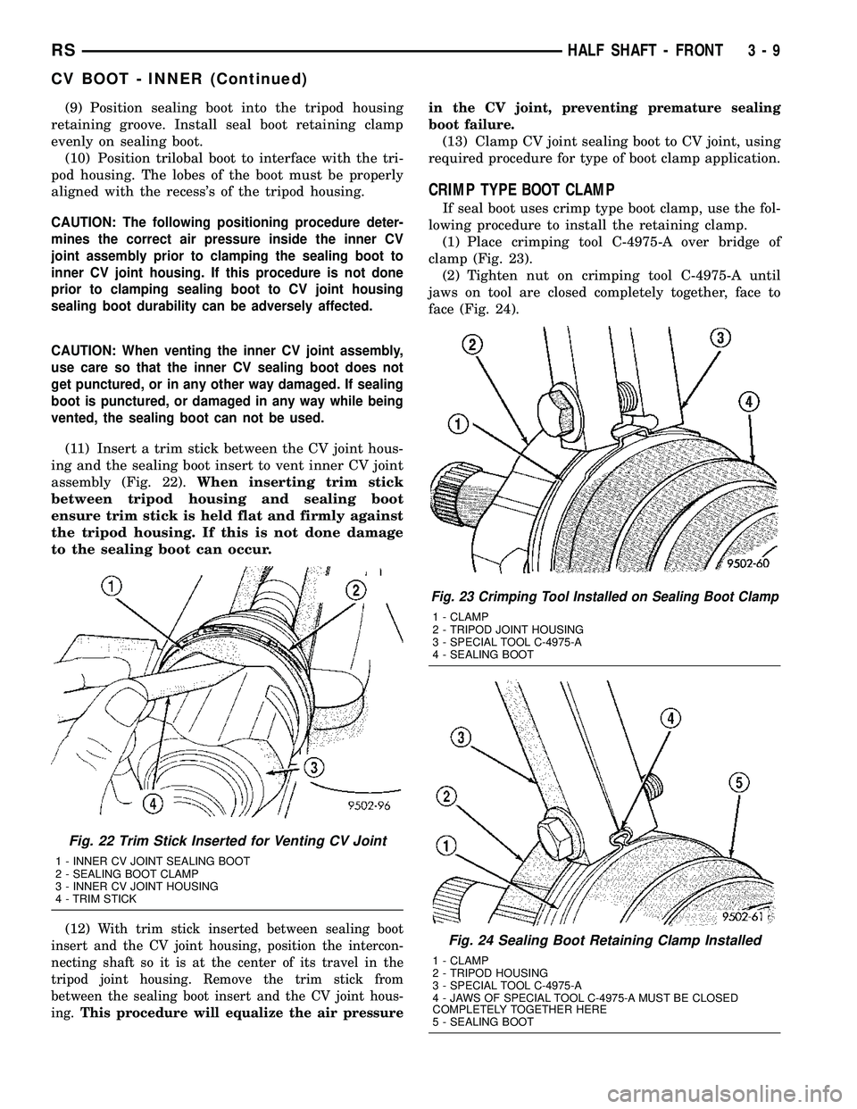
(11) Insert a trim stick between the CV joint hous-
ing and the sealing boot insert to vent inner CV joint
assembly (Fig. 22).When inserting trim stick
between tripod housing and sealing boot
ensure trim stick is held flat and firmly against
the tripod housing. If this is not done damage
to the sealing boot can occur.
(12)
With trim stick inserted between sealing boot
insert and the CV joint housing, position the intercon-
necting shaft so it is at the center of its travel in the
tripod joint housing. Remove the trim stick from
between the sealing boot insert and the CV joint hous-
ing.This procedure will equalize the air pressurein the CV joint, preventing premature sealing
boot failure.
(13) Clamp CV joint sealing boot to CV joint, using
required procedure for type of boot clamp application.
CRIMP TYPE BOOT CLAMP
If seal boot uses crimp type boot clamp, use the fol-
lowing procedure to install the retaining clamp.
(1) Place crimping tool C-4975-A over bridge of
clamp (Fig. 23).
(2) Tighten nut on crimping tool C-4975-A until
jaws on tool are closed completely together, face to
face (Fig. 24).
Fig. 22 Trim Stick Inserted for Venting CV Joint
1 - INNER CV JOINT SEALING BOOT
2 - SEALING BOOT CLAMP
3 - INNER CV JOINT HOUSING
4 - TRIM STICK
Fig. 23 Crimping Tool Installed on Sealing Boot Clamp
1 - CLAMP
2 - TRIPOD JOINT HOUSING
3 - SPECIAL TOOL C-4975-A
4 - SEALING BOOT
Fig. 24 Sealing Boot Retaining Clamp Installed
1 - CLAMP
2 - TRIPOD HOUSING
3 - SPECIAL TOOL C-4975-A
4 - JAWS OF SPECIAL TOOL C-4975-A MUST BE CLOSED
COMPLETELY TOGETHER HERE
5 - SEALING BOOT
RSHALF SHAFT - FRONT3-9
CV BOOT - INNER (Continued)
Page 107 of 2339
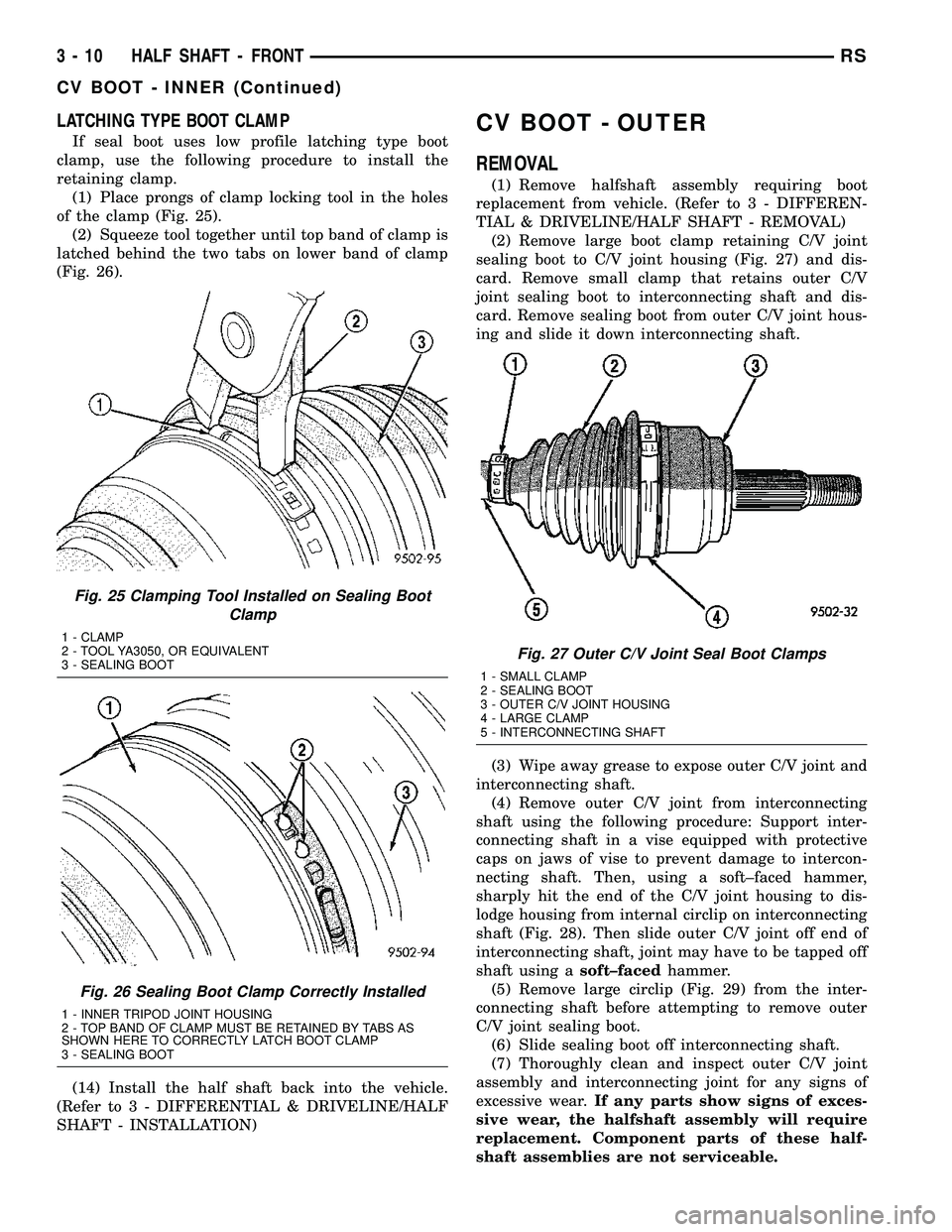
LATCHING TYPE BOOT CLAMP
If seal boot uses low profile latching type boot
clamp, use the following procedure to install the
retaining clamp.
(1) Place prongs of clamp locking tool in the holes
of the clamp (Fig. 25).
(2) Squeeze tool together until top band of clamp is
latched behind the two tabs on lower band of clamp
(Fig. 26).
(14) Install the half shaft back into the vehicle.
(Refer to 3 - DIFFERENTIAL & DRIVELINE/HALF
SHAFT - INSTALLATION)
CV BOOT - OUTER
REMOVAL
(1) Remove halfshaft assembly requiring boot
replacement from vehicle. (Refer to 3 - DIFFEREN-
TIAL & DRIVELINE/HALF SHAFT - REMOVAL)
(2) Remove large boot clamp retaining C/V joint
sealing boot to C/V joint housing (Fig. 27) and dis-
card. Remove small clamp that retains outer C/V
joint sealing boot to interconnecting shaft and dis-
card. Remove sealing boot from outer C/V joint hous-
ing and slide it down interconnecting shaft.
(3) Wipe away grease to expose outer C/V joint and
interconnecting shaft.
(4) Remove outer C/V joint from interconnecting
shaft using the following procedure: Support inter-
connecting shaft in a vise equipped with protective
caps on jaws of vise to prevent damage to intercon-
necting shaft. Then, using a soft±faced hammer,
sharply hit the end of the C/V joint housing to dis-
lodge housing from internal circlip on interconnecting
shaft (Fig. 28). Then slide outer C/V joint off end of
interconnecting shaft, joint may have to be tapped off
shaft using asoft±facedhammer.
(5) Remove large circlip (Fig. 29) from the inter-
connecting shaft before attempting to remove outer
C/V joint sealing boot.
(6) Slide sealing boot off interconnecting shaft.
(7) Thoroughly clean and inspect outer C/V joint
assembly and interconnecting joint for any signs of
excessive wear.If any parts show signs of exces-
sive wear, the halfshaft assembly will require
replacement. Component parts of these half-
shaft assemblies are not serviceable.
Fig. 25 Clamping Tool Installed on Sealing Boot
Clamp
1 - CLAMP
2 - TOOL YA3050, OR EQUIVALENT
3 - SEALING BOOT
Fig. 26 Sealing Boot Clamp Correctly Installed
1 - INNER TRIPOD JOINT HOUSING
2 - TOP BAND OF CLAMP MUST BE RETAINED BY TABS AS
SHOWN HERE TO CORRECTLY LATCH BOOT CLAMP
3 - SEALING BOOT
Fig. 27 Outer C/V Joint Seal Boot Clamps
1 - SMALL CLAMP
2 - SEALING BOOT
3 - OUTER C/V JOINT HOUSING
4 - LARGE CLAMP
5 - INTERCONNECTING SHAFT
3 - 10 HALF SHAFT - FRONTRS
CV BOOT - INNER (Continued)
Page 108 of 2339
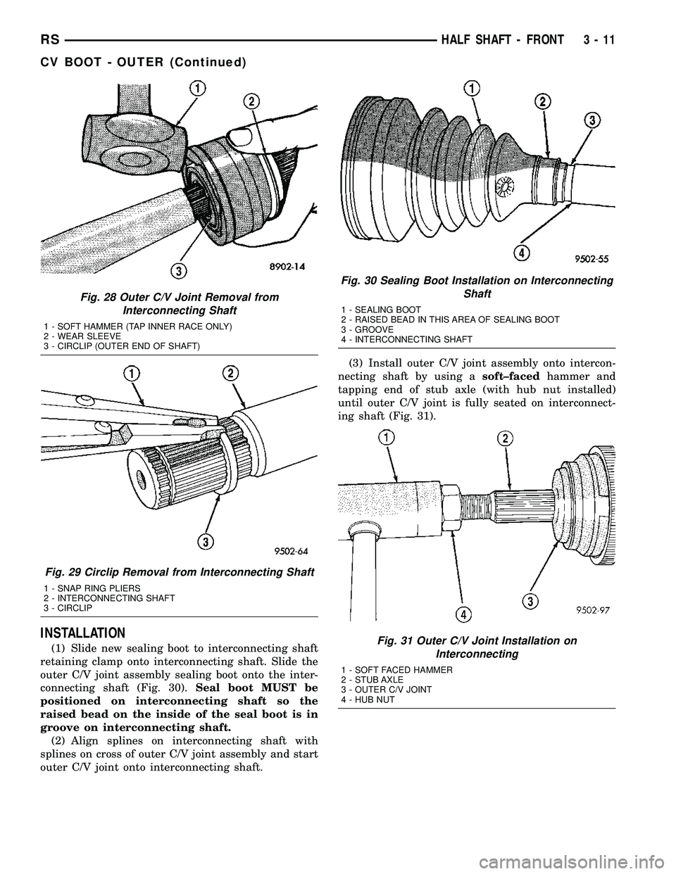
INSTALLATION
(1) Slide new sealing boot to interconnecting shaft
retaining clamp onto interconnecting shaft. Slide the
outer C/V joint assembly sealing boot onto the inter-
connecting shaft (Fig. 30).Seal boot MUST be
positioned on interconnecting shaft so the
raised bead on the inside of the seal boot is in
groove on interconnecting shaft.
(2) Align splines on interconnecting shaft with
splines on cross of outer C/V joint assembly and start
outer C/V joint onto interconnecting shaft.(3) Install outer C/V joint assembly onto intercon-
necting shaft by using asoft±facedhammer and
tapping end of stub axle (with hub nut installed)
until outer C/V joint is fully seated on interconnect-
ing shaft (Fig. 31).
Fig. 28 Outer C/V Joint Removal from
Interconnecting Shaft
1 - SOFT HAMMER (TAP INNER RACE ONLY)
2 - WEAR SLEEVE
3 - CIRCLIP (OUTER END OF SHAFT)
Fig. 29 Circlip Removal from Interconnecting Shaft
1 - SNAP RING PLIERS
2 - INTERCONNECTING SHAFT
3 - CIRCLIP
Fig. 30 Sealing Boot Installation on Interconnecting
Shaft
1 - SEALING BOOT
2 - RAISED BEAD IN THIS AREA OF SEALING BOOT
3 - GROOVE
4 - INTERCONNECTING SHAFT
Fig. 31 Outer C/V Joint Installation on
Interconnecting
1 - SOFT FACED HAMMER
2 - STUB AXLE
3 - OUTER C/V JOINT
4 - HUB NUT
RSHALF SHAFT - FRONT3-11
CV BOOT - OUTER (Continued)
Page 109 of 2339
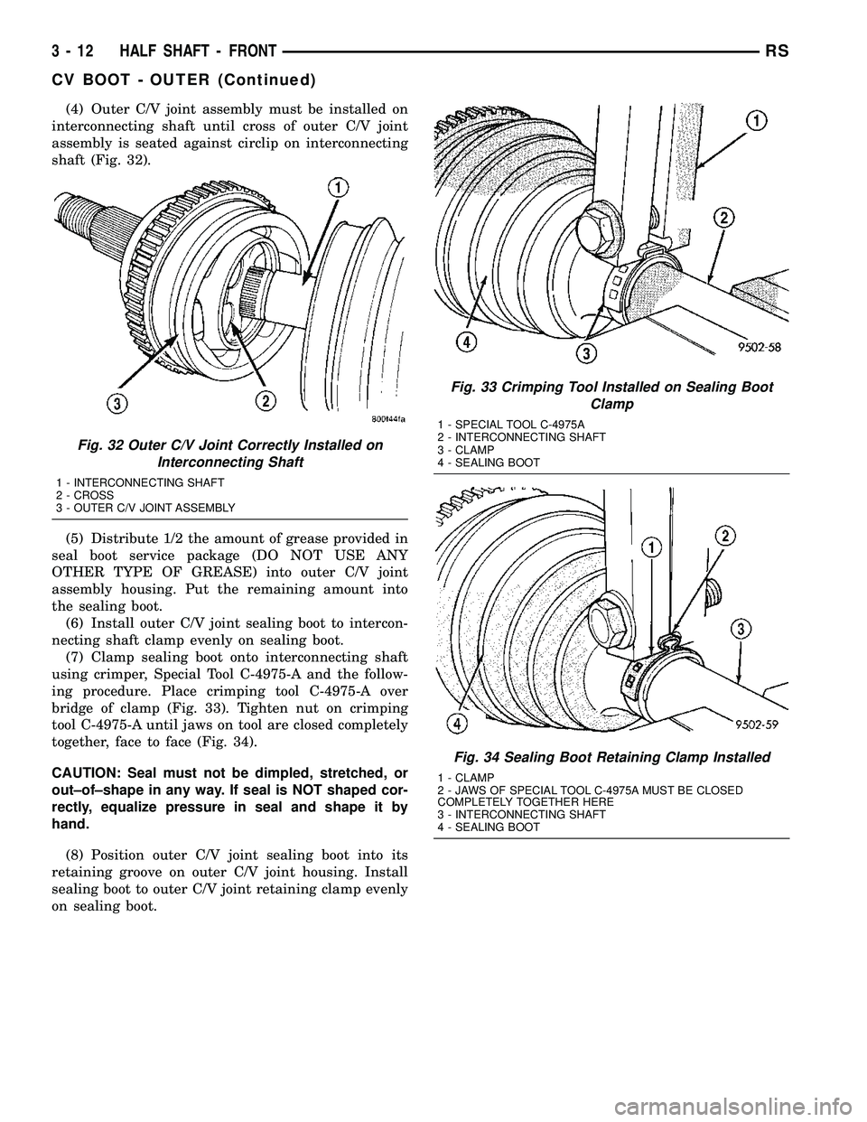
(4) Outer C/V joint assembly must be installed on
interconnecting shaft until cross of outer C/V joint
assembly is seated against circlip on interconnecting
shaft (Fig. 32).
(5) Distribute 1/2 the amount of grease provided in
seal boot service package (DO NOT USE ANY
OTHER TYPE OF GREASE) into outer C/V joint
assembly housing. Put the remaining amount into
the sealing boot.
(6) Install outer C/V joint sealing boot to intercon-
necting shaft clamp evenly on sealing boot.
(7) Clamp sealing boot onto interconnecting shaft
using crimper, Special Tool C-4975-A and the follow-
ing procedure. Place crimping tool C-4975-A over
bridge of clamp (Fig. 33). Tighten nut on crimping
tool C-4975-A until jaws on tool are closed completely
together, face to face (Fig. 34).
CAUTION: Seal must not be dimpled, stretched, or
out±of±shape in any way. If seal is NOT shaped cor-
rectly, equalize pressure in seal and shape it by
hand.
(8) Position outer C/V joint sealing boot into its
retaining groove on outer C/V joint housing. Install
sealing boot to outer C/V joint retaining clamp evenly
on sealing boot.
Fig. 32 Outer C/V Joint Correctly Installed on
Interconnecting Shaft
1 - INTERCONNECTING SHAFT
2 - CROSS
3 - OUTER C/V JOINT ASSEMBLY
Fig. 33 Crimping Tool Installed on Sealing Boot
Clamp
1 - SPECIAL TOOL C-4975A
2 - INTERCONNECTING SHAFT
3 - CLAMP
4 - SEALING BOOT
Fig. 34 Sealing Boot Retaining Clamp Installed
1 - CLAMP
2 - JAWS OF SPECIAL TOOL C-4975A MUST BE CLOSED
COMPLETELY TOGETHER HERE
3 - INTERCONNECTING SHAFT
4 - SEALING BOOT
3 - 12 HALF SHAFT - FRONTRS
CV BOOT - OUTER (Continued)
Page 110 of 2339
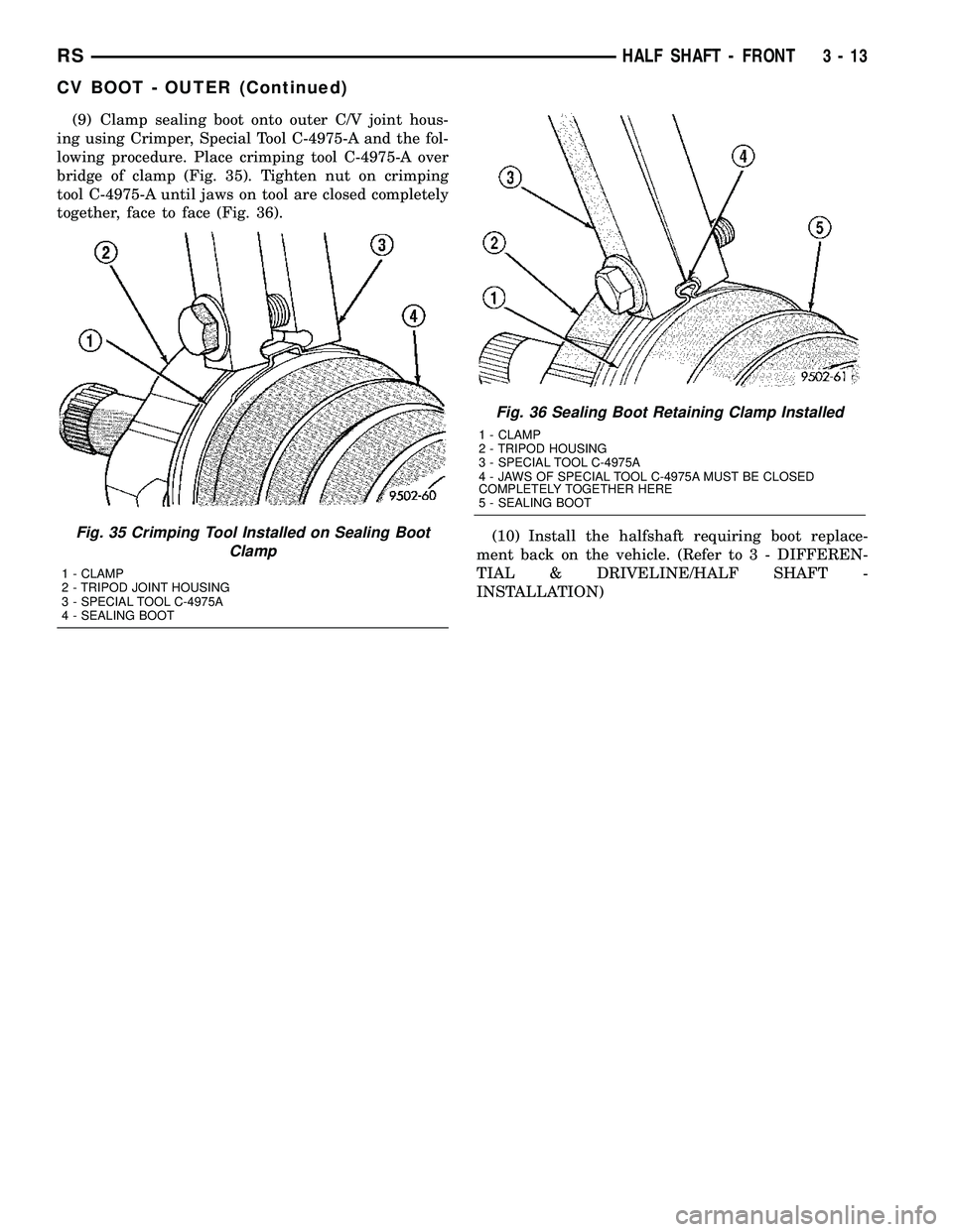
(9) Clamp sealing boot onto outer C/V joint hous-
ing using Crimper, Special Tool C-4975-A and the fol-
lowing procedure. Place crimping tool C-4975-A over
bridge of clamp (Fig. 35). Tighten nut on crimping
tool C-4975-A until jaws on tool are closed completely
together, face to face (Fig. 36).
(10) Install the halfshaft requiring boot replace-
ment back on the vehicle. (Refer to 3 - DIFFEREN-
TIAL & DRIVELINE/HALF SHAFT -
INSTALLATION)
Fig. 36 Sealing Boot Retaining Clamp Installed
1 - CLAMP
2 - TRIPOD HOUSING
3 - SPECIAL TOOL C-4975A
4 - JAWS OF SPECIAL TOOL C-4975A MUST BE CLOSED
COMPLETELY TOGETHER HERE
5 - SEALING BOOT
Fig. 35 Crimping Tool Installed on Sealing Boot
Clamp
1 - CLAMP
2 - TRIPOD JOINT HOUSING
3 - SPECIAL TOOL C-4975A
4 - SEALING BOOT
RSHALF SHAFT - FRONT3-13
CV BOOT - OUTER (Continued)