body CHRYSLER CARAVAN 2005 Service Manual
[x] Cancel search | Manufacturer: CHRYSLER, Model Year: 2005, Model line: CARAVAN, Model: CHRYSLER CARAVAN 2005Pages: 2339, PDF Size: 59.69 MB
Page 542 of 2339
When the ignition switch is moved to the RUN
position, the SKREEM transmits an Radio Frequency
(RF) signal to the transponder in the ignition key.
The SKREEM then waits for a response RF signal
from the transponder in the key. If the response
received identifies the key as valid, the SKREEM
sends a9valid key9message to the Powertrain Con-
trol Module (PCM) over the Programmable Commu-
nication Interface (PCI) data bus. If the response
received identifies the key as invalid or no response
is received from the transponder in the ignition key,
the SKREEM sends an9invalid key9message to the
PCM. The PCM will enable or disable engine opera-
tion based upon the status of the SKREEM mes-
sages. It is important to note that the default
condition in the PCM is9invalid key.9Therefore, if no
response is received by the PCM, the engine will be
immobilized after two (2) seconds of running.
The SKREEM also sends indicator light status
messages to the Mechanical Instrument Cluster
(MIC) to operate the light. This is the method used to
turn the light ON solid or to flash it after the indi-
cator light test is complete to signify a fault in the
SKREES. If the light comes ON and stays ON solid
after the indicator light test, this signifies that the
SKREEM has detected a system malfunction and/or
that the SKREES has become inoperative. If the
SKREEM detects an invalid keyORa key-related
fault exists, the indicator light will flash following
the indicator light test. The SKREEM may also
request an audible chime if the customer key pro-
gramming feature is available and the procedure is
being utilized (Refer to 8 - ELECTRICAL/VEHICLE
THEFT SECURITY/TRANSPONDER KEY - STAN-
DARD PROCEDURE).
REMOTE KEYLESS ENTRY (RKE)
After pressing the lock button on the RKE trans-
mitter, all of the door locks will lock, the illuminated
entry will turn off (providing all doors are closed),
and the VTSS (if equipped) will arm. After pressing
the unlock button, on the RKE transmitter, one time,
the driver door lock will unlock, the illuminated
entry will turn on the courtesy lamps, and the VTSS
(if equipped) will disarm. After pressing the unlock
button a second time, the remaining door locks will
unlock. The Electronic Vehicle Information Center
(EVIC) or the DRBIIItscan tool can reprogram this
feature to unlock all of the door locks with one press
of the unlock button. If the vehicle is equipped with
the memory system, the memory message will iden-
tify which transmitter (1 or 2) sent the signal.The SKREEM is capable of retaining up to 8 indi-
vidual access codes (8 transmitters). If the PRNDL is
in any position except park, the SKREEM will dis-
able the RKE. The 4 button transmitter uses
1-CR2032 battery. The minimum battery life is
approximately 4.7 years based on 20 transmissions a
day at 84ÉF (25ÉC). Use the DRBIIItscan tool or the
Miller Tool 9001 RF Detector to test the RKE trans-
mitter. Use the DRBIIItor the customer program-
ming method to program the RKE system. However,
the SKREEM will only allow RKE programming
when the ignition is in the ON position, the PRNDL
is in park position, and the VTSS (if equipped) is dis-
armed.
TIRE PRESSURE MONITORING (TPM)
The SKREEM monitors the signals from the tire
pressure sensor/transmitters and determines if any
tire has gone below the low pressure threshold LOW
TIRE PRESSURE THRESHOLDS table.
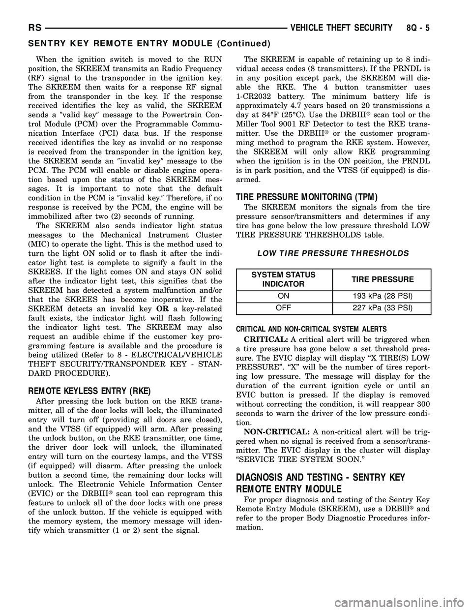
LOW TIRE PRESSURE THRESHOLDS
SYSTEM STATUS
INDICATORTIRE PRESSURE
ON 193 kPa (28 PSI)
OFF 227 kPa (33 PSI)
CRITICAL AND NON-CRITICAL SYSTEM ALERTS
CRITICAL:A critical alert will be triggered when
a tire pressure has gone below a set threshold pres-
sure. The EVIC display will display ªX TIRE(S) LOW
PRESSUREº. ªXº will be the number of tires report-
ing low pressure. The message will display for the
duration of the current ignition cycle or until an
EVIC button is pressed. If the display is removed
without correcting the condition, it will reappear 300
seconds to warn the driver of the low pressure condi-
tion.
NON-CRITICAL:A non-critical alert will be trig-
gered when no signal is received from a sensor/trans-
mitter. The EVIC display in the cluster will display
ªSERVICE TIRE SYSTEM SOON.º
DIAGNOSIS AND TESTING - SENTRY KEY
REMOTE ENTRY MODULE
For proper diagnosis and testing of the Sentry Key
Remote Entry Module (SKREEM), use a DRBllltand
refer to the proper Body Diagnostic Procedures infor-
mation.
RSVEHICLE THEFT SECURITY8Q-5
SENTRY KEY REMOTE ENTRY MODULE (Continued)
Page 543 of 2339

REMOVAL
(1) Disconnect and isolate the battery negative
cable.
(2) Remove the Steering Column Opening Cover
(Refer to 23 - BODY/INSTRUMENT PANEL/STEER-
ING COLUMN OPENING COVER - REMOVAL).
(3) Remove the steering column upper and lower
shrouds (Refer to 19 - STEERING/COLUMN/UPPER
SHROUD - REMOVAL) and (Refer to 19 - STEER-
ING/COLUMN/LOWER SHROUD - REMOVAL).
(4) Disengage the steering column wire harness
from the Sentry Key Remote Entry Module
(SKREEM).
(5) Remove the one screws securing the SKREEM
to the steering column.
(6) Rotate the SKREEM upwards and then to the
side away from the steering column to slide the
SKREEM antenna ring from around the ignition
switch lock cylinder housing.
(7) Remove the SKREEM from the vehicle.
INSTALLATION
(1) Slip the Sentry Key Remote Entry Module
(SKREEM) antenna ring around the ignition switch
lock cylinder housing. Rotate the SKREEM down-
wards and then towards the steering column.
(2) Install the one screws securing the SKREEM to
the steering column.
(3) Connect the steering column wire harness to
the SKREEM.
(4) Install the steering column upper and lower
shrouds (Refer to 19 - STEERING/COLUMN/UPPER
SHROUD - INSTALLATION) and (Refer to 19 -
STEERING/COLUMN/LOWER SHROUD - INSTAL-
LATION).
(5) Install the Steering Column Opening Cover
(Refer to 23 - BODY/INSTRUMENT PANEL/STEER-
ING COLUMN OPENING COVER - INSTALLA-
TION)
(6) Connect the battery negative cable.
TRANSPONDER KEY
DESCRIPTION
The Sentry Key Remote Entry System (SKREES)
uses a transponder chip that is integral to the circuit
board of the integrated ignition key (SKREES and
RKE incorporated) to communicate with the Sentry
Key Remote Entry Module (SKREEM). Ignition keys
are supplied with the vehicle when it is shipped from
the factory.
For export vehicles equipped with SKREES, the
transponder chip is undermolded within the head of
the key.
OPERATION
Each Sentry Key has a unique transponder identi-
fication code permanently programmed into it by the
manufacturer. Likewise, the Sentry Key Remote
Entry Module (SKREEM) has a unique9Secret Key9
code programmed into it by the manufacturer as
well. When a Sentry Key is programmed into the
memory of the SKREEM, the SKREEM stores the
transponder identification code from the Sentry Key,
and the Sentry Key learns the9Secret Key9code from
the SKREEM. Once the Sentry Key learns the
9Secret Key9code of the SKREEM, it is also perma-
nently programmed into the transponder's memory.
Therefore, blank keys for the Sentry Key Remote
Entry System (SKREES) must be programmed by
the SKREEM in addition to being cut to match the
mechanical coding of the ignition lock cylinder. Refer
to Electrical, Vehicle Theft Security, Transponder
Key, Standard Procedure - Transponder Program-
ming.
The Sentry Key's transponder is within the range
of the SKREEM's transceiver antenna ring when it is
inserted into the ignition lock cylinder. When the
ignition switch is turned to the ON position, the
SKREEM communicates with the Sentry Key via a
radio frequency (RF) signal. The SKREEM deter-
mines if a valid key is present based on the informa-
tion it receives from the Sentry Key. If a valid key is
detected, that fact is communicated to the PCM via
the PCI bus and the vehicle is allowed to continue
running. If an invalid key is received by the PCM or
no status at all is communicated, the vehicle will
stall after two (2) seconds of running. The indicator
light will be flashing at this point. The Sentry Key's
transponder can not be repaired. If it is faulty or
damaged, it must be replaced.
Common communication problems:
²Two transponder keys too close together.
²Speed Pass too close to transponder key.
Solid indicator that there is a system failure.
²Loss of PCM communication.
²Failed antenna circuit.
STANDARD PROCEDURE - TRANSPONDER
PROGRAMMING
USING A DRBIIITSCAN TOOL
All Sentry Keys included with the vehicle are pre-
programmed to work with the Sentry Key Remote
Entry System (SKREES) when it is shipped from the
factory. The Sentry Key Remote Entry Module
(SKREEM) can be programmed to recognize up to a
total of eight Sentry Keys. When programming a
blank Sentry Key transponder, the key must first be
cut to match the ignition lock cylinder of the vehicle
for which it will be used. The vehicle's four digit PIN
8Q - 6 VEHICLE THEFT SECURITYRS
SENTRY KEY REMOTE ENTRY MODULE (Continued)
Page 545 of 2339

VTSS/SKIS INDICATOR LAMP
DESCRIPTION
The Sentry Key Remote Entry System (SKREES)
uses an indicator light to convey information on the
status of the system to the customer. This light is
shared with the Vehicle Theft Security System
(VTSS). The light is located in the Mechanical
Instrument Cluster (MIC). The VTSS status is con-
trolled by the Body Control Module (BCM), via Pro-
grammable Communication Interface (PCI) data bus
communication with the MIC, based upon messages
it receives from the Sentry Key Remote Entry Mod-
ule (SKREEM) on the PCI data bus.
OPERATION
The Mechanical Instrument Cluster (MIC) per-
forms a four second bulb check via PCI communica-
tion with the Sentry Key Remote Entry Module
(SKREEM). After the bulb check, the lamp is con-
trolled according to SKREEM messages. Then, the
SKREEM sends messages to the BCM to operate thelight based upon the results of the Sentry Key
Remote Entry System (SKREES) self tests. The light
may be actuated in two possible ways, flashing or on
solid. If the light comes on and stays on solid after a
power-up test, this indicates that the SKREEM has
detected a system malfunction. If the SKREEM
detects an invalid key when the ignition switch is
moved to the ON position, it sends a message on the
PCI bus to the MIC, to flash the light. The SKREEM
can also send a message to flash the light and gen-
erate a single audible chime at the same time. These
two events occurring simultaneously indicate that
the SKIS has been placed into the9Customer Learn9
mode (Refer to 8 - ELECTRICAL/VEHICLE THEFT
SECURITY/TRANSPONDER KEY - STANDARD
PROCEDURE). If the light comes on and stays on
after the power-up test, diagnosis of the SKREES
should be performed using a DRBIIItscan tool and
the appropriate Body Diagnostic Procedures informa-
tion. The light is a Light Emitting Diode (LED) and
is not a serviceable component.
8Q - 8 VEHICLE THEFT SECURITYRS
Page 547 of 2339
OPERATION
FRONT WIPER/WASHER SYSTEM
The windshield washer circuit is protected by a 15
amp Cartridge Fuse located in the IPM. The wiper
motor has permanent magnetic fields. The speeds are
determined by current flow to the appropriate set of
brushes inside the motor. The current flow is con-
trolled by the multi-function switch. The high speed/
low speed relays are located in the IPM. The speed
sensitive intermittent wiper is controlled by the Body
Control Module (BCM). The intermittent mode, with
the vehicle traveling greater than 10.4 mph, has a
range of 0.5 to 18 seconds. With the vehicle traveling
less than 10.4 mph, the time delay doubles to a
range of 1 to 36 seconds. The wiper arms will park at
the base of the windshield just above the cowl cover
after the wiper switch is turned OFF.
The windshield wiper motor and linkage is located
in an integral wiper unit at the rear of the engine
compartment. The wiper unit must be removed to
gain access to the wiper motor.
The front and rear washer systems share the same
washer pump motor.
REAR WIPER/WASHER SYSTEM
When rear wiper operation is required, the BCM
will provide ignition ON voltage to the rear wiper
motor (Export and ATC equipped vehicles only).
When the wiper switch is turned OFF, the BCM pro-
vides circuit ground to operate the motor until the
wipe cycle is complete and the wiper arm returns to
the base of the rear window.
Switch only offers an intermittent rear wiper
mode. The wiper motor will cycle every 7 seconds.
The intermittent delay time is also adjusted based
upon vehicle speed. With the vehicle traveling
greater than 50 mph, the cycle changes to every 5
seconds.
When rear washer is requested by depressing and
holding down the switch, the BCM then provides a
ground for the washer motor. Until the switch is
released, the motor will be in a continuous wipe
mode, then return to an intermittent wipe mode.
DIAGNOSIS AND TESTING
DIAGNOSIS AND TESTING - FRONT WIPER
SYSTEM
The windshield wiper system operates in several
modes:
²Low and high speed normal wipe
²Speed sensitive intermittent wipe
²Wipe after wash
²Park (switch OFF)The windshield wiper circuits are continuously
monitored and controlled by the Body Control Mod-
ule (BCM). If a problem occurs in the electronic com-
ponents, wiring, switch (except integral motor park
switch) and wiper motor a Diagnostic Trouble Code
(DTC) will be stored in the BCM memory. DTC's can
be retrieved using a DRB IIItscan tool. Refer to the
proper Body Diagnostic Procedures manual for DTC
descriptions and retrieval information.
The windshield wiper park switch and circuit is
monitored by the BCM. The park switch and circuit
can be tested using the Wiper System Diagnosis
table.
DIAGNOSIS AND TESTING - FRONT
WIPER/WASHER SWITCH
(1) Remove the multi-function switch (Refer to 8 -
ELECTRICAL/LAMPS/LIGHTING - EXTERIOR/
MULTI-FUNCTION SWITCH - REMOVAL).
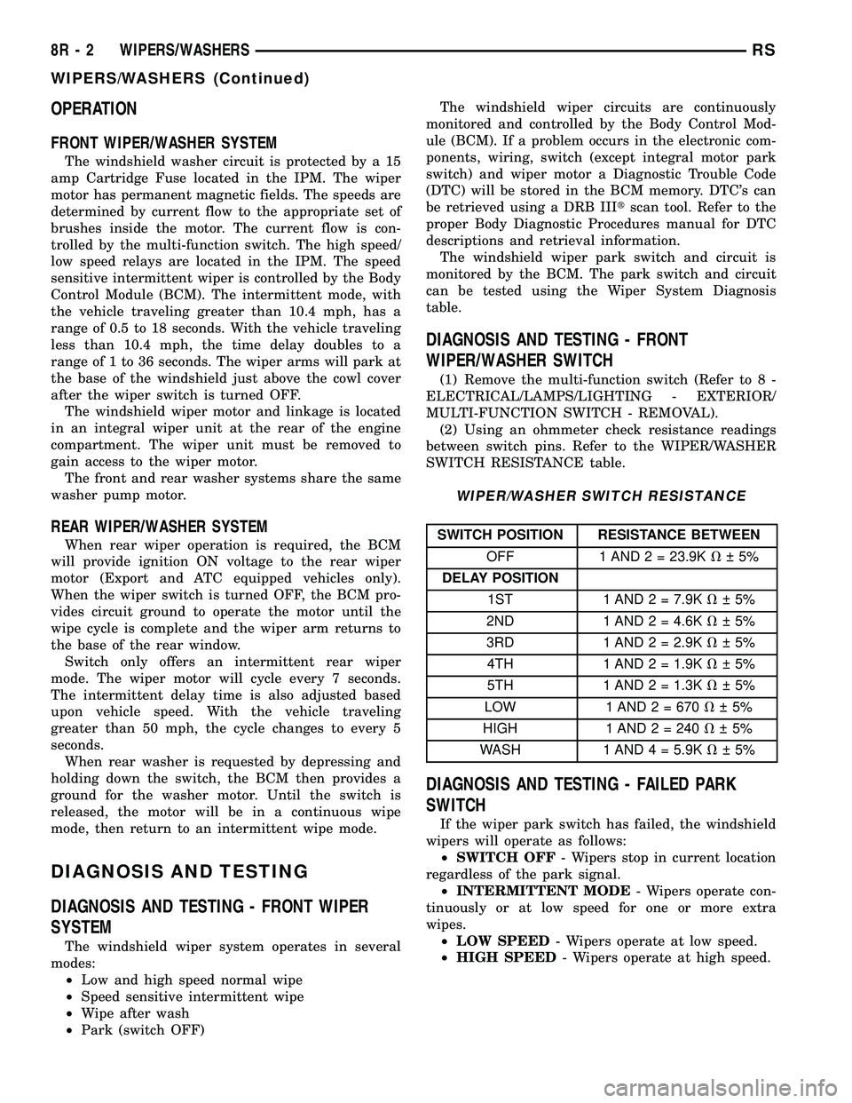
(2) Using an ohmmeter check resistance readings
between switch pins. Refer to the WIPER/WASHER
SWITCH RESISTANCE table.
WIPER/WASHER SWITCH RESISTANCE
SWITCH POSITION RESISTANCE BETWEEN
OFF 1 AND 2 = 23.9KV 5%
DELAY POSITION
1ST 1 AND 2 = 7.9KV 5%
2ND 1 AND 2 = 4.6KV 5%
3RD 1 AND 2 = 2.9KV 5%
4TH 1 AND 2 = 1.9KV 5%
5TH 1 AND 2 = 1.3KV 5%
LOW 1 AND 2 = 670V 5%
HIGH 1 AND2=240V 5%
WASH 1 AND 4 = 5.9KV 5%
DIAGNOSIS AND TESTING - FAILED PARK
SWITCH
If the wiper park switch has failed, the windshield
wipers will operate as follows:
²SWITCH OFF- Wipers stop in current location
regardless of the park signal.
²INTERMITTENT MODE- Wipers operate con-
tinuously or at low speed for one or more extra
wipes.
²LOW SPEED- Wipers operate at low speed.
²HIGH SPEED- Wipers operate at high speed.
8R - 2 WIPERS/WASHERSRS
WIPERS/WASHERS (Continued)
Page 549 of 2339
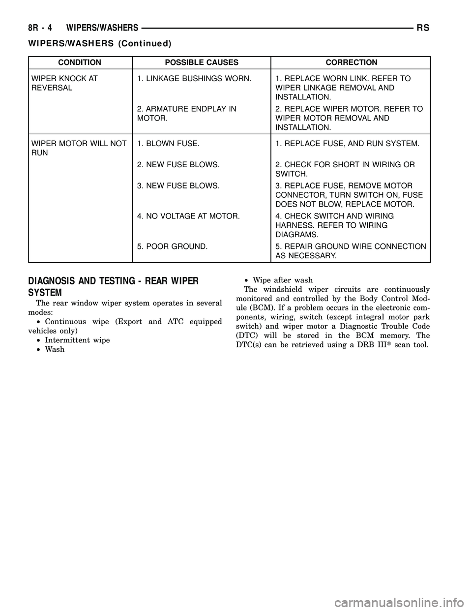
CONDITION POSSIBLE CAUSES CORRECTION
WIPER KNOCK AT
REVERSAL1. LINKAGE BUSHINGS WORN. 1. REPLACE WORN LINK. REFER TO
WIPER LINKAGE REMOVAL AND
INSTALLATION.
2. ARMATURE ENDPLAY IN
MOTOR.2. REPLACE WIPER MOTOR. REFER TO
WIPER MOTOR REMOVAL AND
INSTALLATION.
WIPER MOTOR WILL NOT
RUN1. BLOWN FUSE. 1. REPLACE FUSE, AND RUN SYSTEM.
2. NEW FUSE BLOWS. 2. CHECK FOR SHORT IN WIRING OR
SWITCH.
3. NEW FUSE BLOWS. 3. REPLACE FUSE, REMOVE MOTOR
CONNECTOR, TURN SWITCH ON, FUSE
DOES NOT BLOW, REPLACE MOTOR.
4. NO VOLTAGE AT MOTOR. 4. CHECK SWITCH AND WIRING
HARNESS. REFER TO WIRING
DIAGRAMS.
5. POOR GROUND. 5. REPAIR GROUND WIRE CONNECTION
AS NECESSARY.
DIAGNOSIS AND TESTING - REAR WIPER
SYSTEM
The rear window wiper system operates in several
modes:
²Continuous wipe (Export and ATC equipped
vehicles only)
²Intermittent wipe
²Wash²Wipe after wash
The windshield wiper circuits are continuously
monitored and controlled by the Body Control Mod-
ule (BCM). If a problem occurs in the electronic com-
ponents, wiring, switch (except integral motor park
switch) and wiper motor a Diagnostic Trouble Code
(DTC) will be stored in the BCM memory. The
DTC(s) can be retrieved using a DRB IIItscan tool.
8R - 4 WIPERS/WASHERSRS
WIPERS/WASHERS (Continued)
Page 551 of 2339

CONDITION POSSIBLE CAUSES CORRECTION
WASHER SYSTEM WILL
NOT FLOW WASHER
FLUID.1. NO WASHER FLUID IN
RESERVOIR.1. FILL WASHER RESERVOIR.
2. IPM FUSE #33 BLOWN. 2. SHORT OR DEFECTIVE CIRCUIT
BETWEEN IPM PIN 11 AND WASHER
PUMP MOTOR CONNECTOR POSITIVE
TERMINAL 2. INTERNAL SHORT IN IPM. IF
NOT OK, REPAIR CIRCUIT OR REFER TO
IPM DIAGNOSTIC PROCEDURES IN
WIRING DIAGRAMS.
3. WASHER HOSE NOT
FLOWING WASHER FLUID.3. ASSURE WASHER HOSE IS NOT
PINCHED, LOOSE, BROKEN OR
DISCONNECTED. IF NOT OK, PROPERLY
ROUTE OR REPAIR WASHER HOSE.
4. MOTOR CONNECTOR
LOOSE.4. PROPERLY SEAT AND LOCK
CONNECTOR TO MOTOR.
5. MOTOR CONNECTOR
TERMINALS BENT.5. REPAIR TERMINALS AND PROPERLY
SEAT CONNECTOR TO MOTOR.
6. OPEN CIRCUIT TO OR
FROM WASHER SELECT
SWITCH (EXPORT AND ATC
EQUIPPED VEHICLES ONLY).6. OPEN OR DEFECTIVE CIRCUIT
BETWEEN IPM BODY CONTROLLER PIN
27 AND WASHER SELECT SWITCH PIN 4,
OR OPEN OR DEFECTIVE CIRCUIT
BETWEEN IPM BODY CONTROLLER PIN
22 AND WASHER SELECT SWITCH PIN 2.
IF NOT OK, REPAIR CIRCUIT.
7. OPEN OR DEFECTIVE
WASHER SELECT SWITCH.7. REFERO TO THE PROPER BODY
DIAGNOSTIC PROCEDURES
INFORMATION ON MANUAL
TEMPERATURE CONTROLS.
8. OPEN POWER CIRCUIT TO
MOTOR.8. OPEN OR DEFECTIVE CIRCUIT
BETWEEN IPM CONNECTOR TERMINAL 11
AND WASHER MOTOR CONNECTOR
POSITIVE TERMINAL 2. INTERNAL OPEN
IN IPM. IF NOT OK, REPAIR CIRCUIT OR
REFER TO IPM DIAGNOSTIC
PROCEDURES IN WIRING DIAGRAMS.
9. OPEN OR DEFECTIVE
MOTOR GROUND CIRCUIT.9. OPEN OR DEFECTIVE CIRCUIT
BETWEEN IPM CONNECTOR TERMINAL
20 AND WASHER MOTOR CONNECTOR
NEGATIVE TERMINAL 1. INTERNAL OPEN
IN IPM. IF NOT OK, REPAIR CIRCUIT OR
REFER TO IPM DIAGNOSTIC
PROCEDURES IN WIRING DIAGRAMS.
10. OPEN CIRCUIT IN MOTOR. 10. CHECK FOR OPEN CIRCUIT IN MOTOR
BETWEEN POSITIVE TERMINAL 2 AND
NEGATIVE TERMINAL 1. IF NOT OK,
REPLACE WASHER MOTOR.
11. SEIZED MOTOR BEARINGS. 11. APPLY DIRECT BATTERY VOLTAGE TO
MOTOR TERMINALS. IF MOTOR DOES
NOT RUN, REPLACE MOTOR.
8R - 6 WIPERS/WASHERSRS
WIPERS/WASHERS (Continued)
Page 552 of 2339
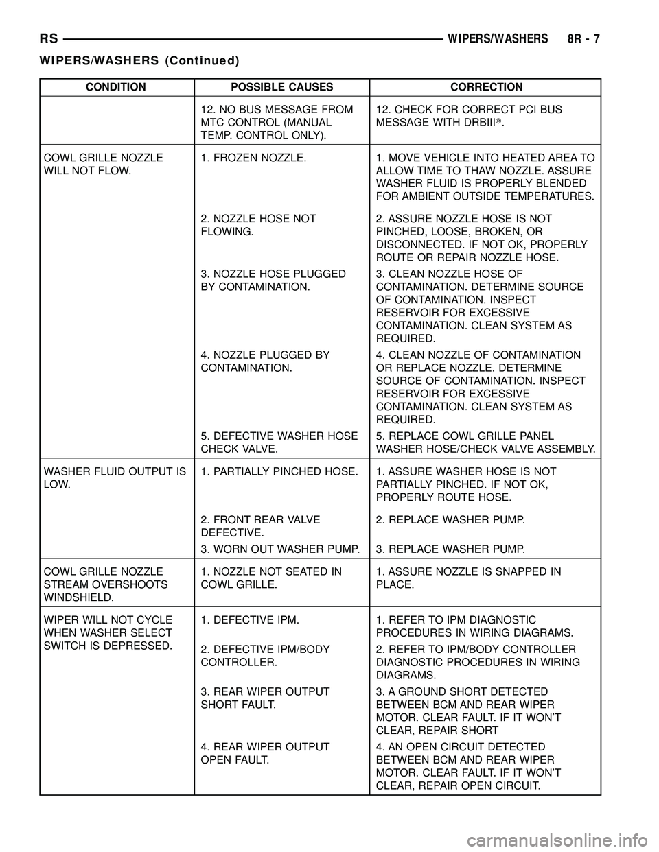
CONDITION POSSIBLE CAUSES CORRECTION
12. NO BUS MESSAGE FROM
MTC CONTROL (MANUAL
TEMP. CONTROL ONLY).12. CHECK FOR CORRECT PCI BUS
MESSAGE WITH DRBIIIT.
COWL GRILLE NOZZLE
WILL NOT FLOW.1. FROZEN NOZZLE. 1. MOVE VEHICLE INTO HEATED AREA TO
ALLOW TIME TO THAW NOZZLE. ASSURE
WASHER FLUID IS PROPERLY BLENDED
FOR AMBIENT OUTSIDE TEMPERATURES.
2. NOZZLE HOSE NOT
FLOWING.2. ASSURE NOZZLE HOSE IS NOT
PINCHED, LOOSE, BROKEN, OR
DISCONNECTED. IF NOT OK, PROPERLY
ROUTE OR REPAIR NOZZLE HOSE.
3. NOZZLE HOSE PLUGGED
BY CONTAMINATION.3. CLEAN NOZZLE HOSE OF
CONTAMINATION. DETERMINE SOURCE
OF CONTAMINATION. INSPECT
RESERVOIR FOR EXCESSIVE
CONTAMINATION. CLEAN SYSTEM AS
REQUIRED.
4. NOZZLE PLUGGED BY
CONTAMINATION.4. CLEAN NOZZLE OF CONTAMINATION
OR REPLACE NOZZLE. DETERMINE
SOURCE OF CONTAMINATION. INSPECT
RESERVOIR FOR EXCESSIVE
CONTAMINATION. CLEAN SYSTEM AS
REQUIRED.
5. DEFECTIVE WASHER HOSE
CHECK VALVE.5. REPLACE COWL GRILLE PANEL
WASHER HOSE/CHECK VALVE ASSEMBLY.
WASHER FLUID OUTPUT IS
LOW.1. PARTIALLY PINCHED HOSE. 1. ASSURE WASHER HOSE IS NOT
PARTIALLY PINCHED. IF NOT OK,
PROPERLY ROUTE HOSE.
2. FRONT REAR VALVE
DEFECTIVE.2. REPLACE WASHER PUMP.
3. WORN OUT WASHER PUMP. 3. REPLACE WASHER PUMP.
COWL GRILLE NOZZLE
STREAM OVERSHOOTS
WINDSHIELD.1. NOZZLE NOT SEATED IN
COWL GRILLE.1. ASSURE NOZZLE IS SNAPPED IN
PLACE.
WIPER WILL NOT CYCLE
WHEN WASHER SELECT
SWITCH IS DEPRESSED.1. DEFECTIVE IPM. 1. REFER TO IPM DIAGNOSTIC
PROCEDURES IN WIRING DIAGRAMS.
2. DEFECTIVE IPM/BODY
CONTROLLER.2. REFER TO IPM/BODY CONTROLLER
DIAGNOSTIC PROCEDURES IN WIRING
DIAGRAMS.
3. REAR WIPER OUTPUT
SHORT FAULT.3. A GROUND SHORT DETECTED
BETWEEN BCM AND REAR WIPER
MOTOR. CLEAR FAULT. IF IT WON'T
CLEAR, REPAIR SHORT
4. REAR WIPER OUTPUT
OPEN FAULT.4. AN OPEN CIRCUIT DETECTED
BETWEEN BCM AND REAR WIPER
MOTOR. CLEAR FAULT. IF IT WON'T
CLEAR, REPAIR OPEN CIRCUIT.
RSWIPERS/WASHERS8R-7
WIPERS/WASHERS (Continued)
Page 553 of 2339

CONDITION POSSIBLE CAUSES CORRECTION
5. NO BUS MESSAGE FROM
MTC CONTROL (MANUAL
TEMP. CONTROL ONLY).5. REFER TO PROPER BODY DIAGNOSTIC
INFORMATION OR USE DRBIIITTO CHECK
PROPER MESSAGE STATUS.
WASHER OPERATES
INTERMITTENTLY.1. INTERMITTENT MOTOR
GROUND.INTERMITTENT GROUND BETWEEN
MOTOR CONNECTOR TERMINAL 1 AND
IPM PIN 20.
2. INTERMITTENT OPEN IN
WASHER SELECT SWITCH.2. (Refer to 8 - ELECTRICAL/LAMPS/
LIGHTING - EXTERIOR/MULTI-FUNCTION
SWITCH - DIAGNOSIS AND TESTING).
3. DEFECTIVE WASHER
MOTOR.3. REPLACE WASHER PUMP.
LOW WASHER FLUID
LEVEL INDICATOR
INOPERATIVE.1. LOOSE FLUID LEVEL
SENSOR CONNECTOR.1. PROPERLY SEAT CONNECTOR TO LOW
FLUID LEVEL SENSOR AND LOCK.
2. OPEN POWER CIRCUIT TO
FLUID LEVEL SENSOR.2. OPEN OR DEFECTIVE CIRCUIT
BETWEEN IPM CONNECTOR TERMINAL 7
AND THE LOW FLUID LEVEL SENSOR
CONNECTOR TERMINAL 2. IF NOT OK,
REPAIR CIRCUIT.
3. OPEN GROUND CIRCUIT. 3. OPEN OR DEFECTIVE CIRCUIT
BETWEEN FLUID LEVEL SENSOR
CONNECTOR TERMINAL 1 AND FLOOR
GROUND 1.
4. DEFECTIVE IPM. 4. REFER TO IPM DIAGNOSTIC
PROCEDURES IN WIRING DIAGRAMS.
5. FLUID LEVEL SENSOR
SWITCH OPEN OR
DEFECTIVE.5. APPLY OHMMETER TO THE SWITCH
TERMINALS TO CHECK FOR COMPLETE
CIRCUIT. CYCLE SWITCH FLOAT BACK
AND FORTH BY FILLING AND DEPLETING
RESERVOIR OF WASHER FLUID TO
CHECK FOR PROPER SWITCH FUNCTION.
IF NOT OK, REPLACE LOW FLUID LEVEL
SENSOR SWITCH.
LEAKING WASHER FLUID. 1. PUMP OR SENSOR
GROMMET DEFECTIVE.1. PROPERLY SEAT PUMP OR SENSOR IN
GROMMET. IF NOT OK, REPLACE PUMP
OR SENSOR GROMMET.
2. LEAKING WASHER PUMP. 2. REPLACE WASHER PUMP.
3. LEAKING FLUID LEVEL
SENSOR.3. REPLACE FLUID LEVEL SENSOR.
4. LEAKING OR DEFECTIVE
RESERVOIR BODY.4. REPLACE RESERVOIR BODY.
8R - 8 WIPERS/WASHERSRS
WIPERS/WASHERS (Continued)
Page 555 of 2339

(5) Remove wiper linkage from motor crank. DO
NOT remove crank from motor.
(6) Remove bolts holding wiper motor and remove
motor.
INSTALLATION
(1) Place wiper module on a suitable work surface.
(2) Install wiper linkage into wiper unit.
(3) Connect wire connectors to wiper motor.
(4) Place the wiper module into engine compart-
ment and connect wiper module wire connector to
engine wire harness (Fig. 7).
(5) Install the four backwall bolts and four brace
nuts to wiper module.
(6) Operate wiper motor and verify that the wiper
motor parks when wiper switch is turned OFF.
REAR WIPER ARM
REMOVAL
(1) Remove arm nut cap.
(2) Remove wiper arm nut.
(3) Pull wiper from pivot by rocking back and
forth.
INSTALLATION
(1) Verify that wipers are in parked position.
(2) Position arm on pivot.
(3) Install wiper arm nut and torque to 20 N´m
(175 in. lbs.).
REAR WIPER MOTOR
REMOVAL
(1) Disconnect and isolate the battery negative
cable.
(2) Remove rear wiper arm. (Refer to 8 - ELEC-
TRICAL/WIPERS/WASHERS/REAR WIPER ARM -
REMOVAL) in this section.
(3) Open liftgate.
(4) Remove liftgate trim panel. (Refer to 23 -
BODY/DECKLID/HATCH/LIFTGATE/TAILGATE/
TRIM PANEL - REMOVAL).
(5) Disconnect wire connector from rear wiper
motor.
(6) Remove screws holding rear wiper motor to lift-
gate.
(7) Remove wiper motor from liftgate.
INSTALLATION
(1) Position the wiper motor in the liftgate.
(2) Install the retaining screws.
(3) Connect the wire harness connector.(4) Install the liftgate trim panel. (Refer to 23 -
BODY/DECKLID/HATCH/LIFTGATE/TAILGATE/
TRIM PANEL - INSTALLATION).
(5) Connect wire connector to rear wiper motor.
(6) Install the screws holding rear wiper motor to
liftgate.
(7) Install the wiper motor to the liftgate.
(8) Close the liftgate.
(9) Install the wiper arm. (Refer to 8 - ELECTRI-
CAL/WIPERS/WASHERS/REAR WIPER ARM -
INSTALLATION) in this section.
(10) Connect the battery negative cable.
REAR WIPER/WASHER
SWITCH
DESCRIPTION
On Automatic Temperature Control (ATC) vehicles
only, the rear window wiper/washer switches are
located on the center bezel with the hazard and
heated seat switches (Fig. 3). They are not service-
able separately from the hazard and heated seat
switches. If defective, the entire switch assembly
must be replaced.
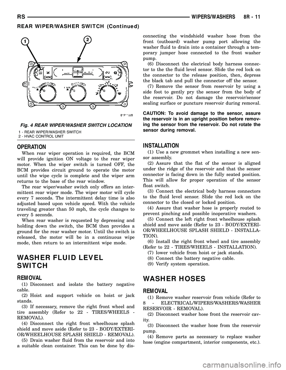
On Manual Temperature Control (MTC) vehicles
only, the rear window wiper/washer switch is located
on the HVAC control head (Fig. 4) attached to the
center bezel. They are not serviceable separately
from the control head. If found faulty, the entire
MTC head must be replaced.
Fig. 3 INSTRUMENT PANEL CENTER BEZEL
1 - TRIM BEZEL
2 - IN CAR TEMPERATURE SENSOR
3 - A/C REQUEST SWITCH
4 - REAR WINDOW DEFOGGER/HEATED MIRRORS SWITCH
COMBO
5 - FRONT WINDOW DEFROSTER MODE SELECTOR
8R - 10 WIPERS/WASHERSRS
FRONT WIPER MOTOR (Continued)
Page 556 of 2339
OPERATION
When rear wiper operation is required, the BCM
will provide ignition ON voltage to the rear wiper
motor. When the wiper switch is turned OFF, the
BCM provides circuit ground to operate the motor
until the wipe cycle is complete and the wiper arm
returns to the base of the rear window.
The rear wiper/washer switch only offers an inter-
mittent rear wiper mode. The wiper motor will cycle
every 7 seconds. The intermittent delay time is also
adjusted based upon vehicle speed. With the vehicle
traveling greater than 50 mph, the cycle changes to
every 5 seconds.
When rear washer is requested by depressing and
holding down the switch, the BCM then provides a
ground for the rear washer motor. Until the switch is
released, the motor will be in a continuous wipe
mode, then return to an intermittent wipe mode.
WASHER FLUID LEVEL
SWITCH
REMOVAL
(1) Disconnect and isolate the battery negative
cable.
(2) Hoist and support vehicle on hoist or jack
stands.
(3) If necessary, remove the right front wheel and
tire assembly (Refer to 22 - TIRES/WHEELS -
REMOVAL).
(4) Disconnect the right front wheelhouse splash
shield and move aside (Refer to 23 - BODY/EXTERI-
OR/WHEELHOUSE SPLASH SHIELD - REMOVAL).
(5) Drain washer fluid from the reservoir and into
a suitable clean container. This can be done by dis-connecting the windshield washer hose from the
front (outboard) washer pump port allowing the
washer fluid to drain into a container through a tem-
porary jumper hose connected to the front washer
pump.
(6) Disconnect the electrical body harness connec-
tor to the the fluid level sensor. Slide the red lock on
the connector to the release position, then, depress
the black tab and pull the connector off the sensor.
(7) Remove the sensor from reservoir by using a
side foot to gently pry the sensor from the body of
the reservoir. Do not damage the reservoir/sensor
sealing surface or puncture reservoir during removal.
CAUTION: To avoid damage to the sensor, assure
the reservoir is in an upright position before remov-
ing the sensor from the reservoir. Do not rotate the
sensor during removal.
INSTALLATION
(1) Use a new grommet when installing a new sen-
sor assembly.
(2) Assure that the flat of the sensor is aligned
under the ridge of the reservoir and that the sensor
connector is facing down in the fully seated position.
This will allow for proper operation of the sensor
float switch.
(3) Connect the electrical body harness connectors
to the fluid level sensor. Slide the red lock on the
connector to the closed or locked position.
(4) Assure that washer hose is properly routed to
prevent pinching and possible inoperative washers.
(5) Connect the left right front wheelhouse splash
shield and move aside (Refer to 23 - BODY/EXTERI-
OR/WHEELHOUSE SPLASH SHIELD - INSTALLA-
TION).
(6) Install the right front wheel and tire assembly
(Refer to 22 - TIRES/WHEELS - INSTALLATION).
(7) lower vehicle from hoist or jack stands.
(8) Connect the battery negative cable.
(9) Verify system operation.
WASHER HOSES
REMOVAL
(1) Remove washer reservoir from vehicle (Refer to
8 - ELECTRICAL/WIPERS/WASHERS/WASHER
RESERVOIR - REMOVAL).
(2) Disconnect washer hose front the reservoir cav-
ity.
(3) Disconnect the washer hose from the reservoir
pump.
(4) Remove parts as necessary to replace washer
hose (engine compartment, interior components, etc.).
Fig. 4 REAR WIPER/WASHER SWITCH LOCATION
1 - REAR WIPER/WASHER SWITCH
2 - HVAC CONTROL UNIT
RSWIPERS/WASHERS8R-11
REAR WIPER/WASHER SWITCH (Continued)