radiator CHRYSLER CARAVAN 2005 Workshop Manual
[x] Cancel search | Manufacturer: CHRYSLER, Model Year: 2005, Model line: CARAVAN, Model: CHRYSLER CARAVAN 2005Pages: 2339, PDF Size: 59.69 MB
Page 1089 of 2339

RADIATOR FAN NO. 1 (DIESEL) - GRAY 2 WAY
CAV CIRCUIT FUNCTION
1 N201 12DB/LG RADIATOR FAN RELAY NO. 1 OUTPUT
2 N202 12DB/OR RADIATOR FAN NO. 1 CONTROL
RADIATOR FAN NO. 1 (GAS) - BLACK 2 WAY
CAV CIRCUIT FUNCTION
1 N23 12DB/DG RADIATOR FAN RELAY OUTPUT
2 Z223 12BK/DG GROUND
RADIATOR FAN NO. 2 (DIESEL) - GRAY 2 WAY
CAV CIRCUIT FUNCTION
1 N112 12DB/OR RADIATOR FAN RELAY NO. 2 AND NO. 3 COMMON
OUTPUT
2 Z823 12BK/DG GROUND
RADIATOR FAN NO. 2 (GAS) - BLACK 2 WAY
CAV CIRCUIT FUNCTION
1 N23 12DB/DG RADIATOR FAN RELAY OUTPUT
2 Z223 12BK/DG GROUND
8W - 80 - 120 8W-80 CONNECTOR PIN-OUTSRS
Page 1090 of 2339

RADIATOR FAN RELAY (GAS)-4WAY
CAV CIRCUIT FUNCTION
1 A112 12OR/RD FUSED B(+)
2 N23 12DB/DG RADIATOR FAN RELAY OUTPUT
3 Z723 18BK/DG GROUND
4 N173 18DB/VT RAD FAN RELAY CONTROL
RADIATOR FAN RELAY NO. 1 (DIESEL) - BLUE 9 WAY
CAV CIRCUIT FUNCTION
1- -
2 N201 12DB/LG RADIATOR FAN RELAY NO. 1 OUTPUT
3- -
4 K342 16BR/WT ECM/PCM RELAY OUTPUT
5- -
6 N210 18DB/DG LOW SPEED RADIATOR FAN RELAY CONTROL
7- -
8 A201 12RD/LG FUSED B(+)
9- -
RADIATOR FAN RELAY NO. 2 (DIESEL) - BLUE 9 WAY
CAV CIRCUIT FUNCTION
1- -
2 N112 12DB/OR RADIATOR FAN RELAY NO. 2 AND NO. 3 COMMON
OUTPUT
3- -
4 K342 16BR/WT ECM/PCM RELAY OUTPUT
5- -
6 N122 18DB/YL HIGH SPEED RADIATOR FAN DUAL RELAY CONTROL
7- -
8 A112 12OR/RD FUSED B(+)
9- -
RS8W-80 CONNECTOR PIN-OUTS8W - 80 - 121
Page 1091 of 2339

RADIATOR FAN RELAY NO. 3 (DIESEL) - BLUE 9 WAY
CAV CIRCUIT FUNCTION
1- -
2 Z823 12BK/DG GROUND
3- -
4 K342 16BR/WT ECM/PCM RELAY OUTPUT
5 N112 12DB/OR RADIATOR FAN RELAY NO. 2 AND NO. 3 COMMON
OUTPUT
6 N122 18DB/YL HIGH SPEED RADIATOR FAN DUAL RELAY CONTROL
7- -
8 N202 12DB/OR RADIATOR FAN NO. 1 CONTROL
9- -
RADIO C1 - 22 WAY
CAV CIRCUIT FUNCTION
1 A114 16GY/RD FUSED B(+) (I.O.D.)
2 F306 18DB/PK FUSED ACCESSORY RELAY OUTPUT
3 E14 20OR/TN PANEL LAMPS DRIVER
4- -
5- -
6- -
7 X54 20GY (LOWLINE) RIGHT FRONT SPEAKER (+)
8 X56 20GY/BR (LOWLINE) RIGHT FRONT SPEAKER (-)
9 X55 20DG/BR (LOWLINE) LEFT FRONT SPEAKER (-)
10 X53 20DG (LOWLINE) LEFT FRONT SPEAKER (+)
11 Z514 16BK/LG GROUND
12 A114 16GY/RD FUSED B(+) (I.O.D.)
13 X60 20GY/YL (EXPORT) RADIO 12 VOLT OUTPUT
14 D25 20WT/VT PCI BUS
15 - -
16 - -
17 - -
18 X51 22DG/DB LEFT REAR SPEAKER (+)
19 X57 22DG/OR LEFT REAR SPEAKER (-)
20 X58 22GY/OR RIGHT REAR SPEAKER (-)
21 X52 22GY/DB RIGHT REAR SPEAKER (+)
22 Z515 16BK GROUND
8W - 80 - 122 8W-80 CONNECTOR PIN-OUTSRS
Page 1114 of 2339

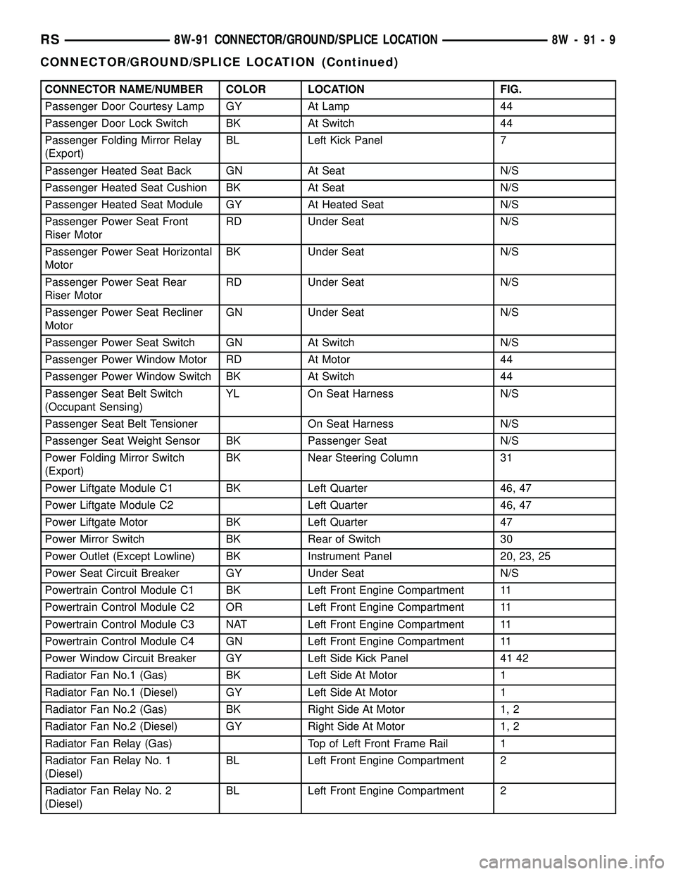
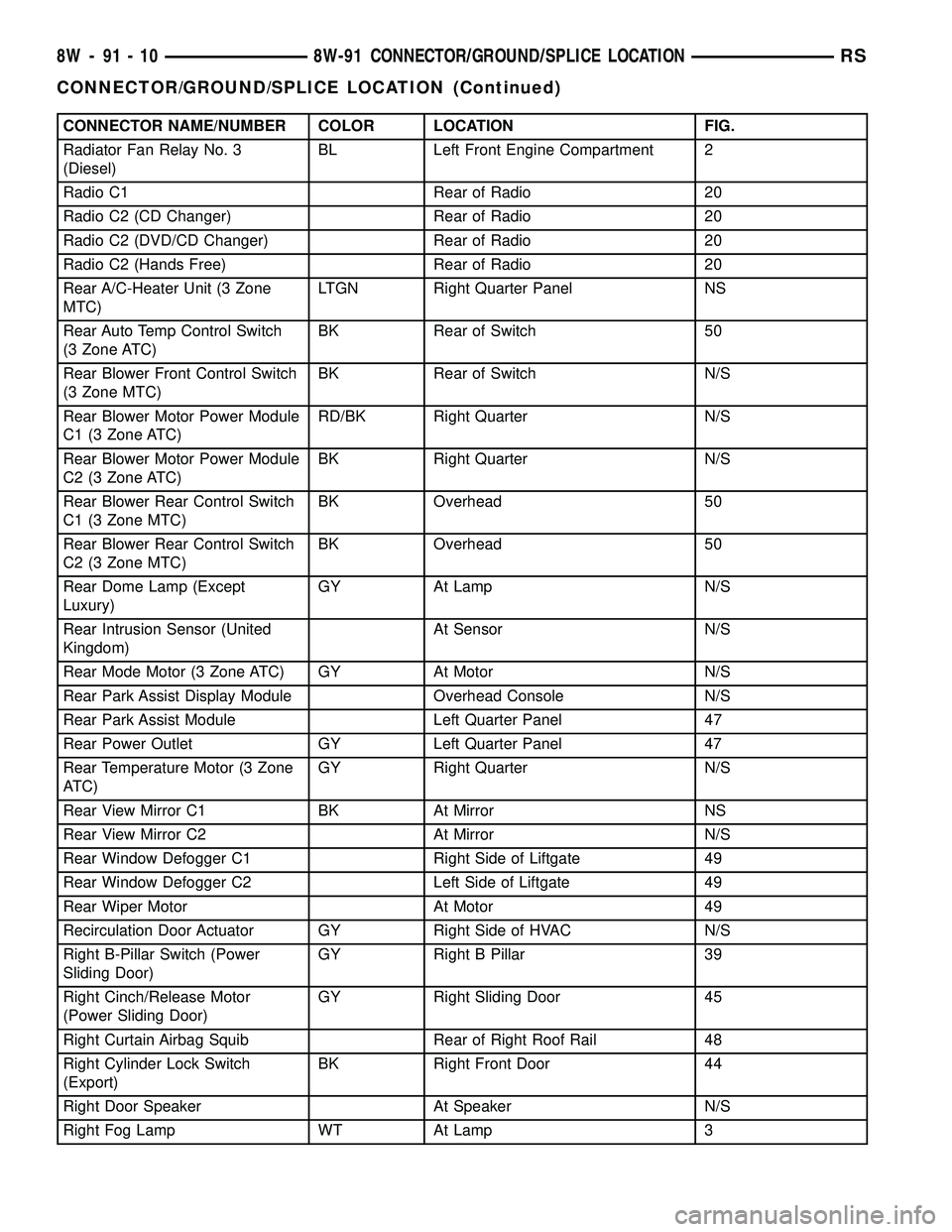
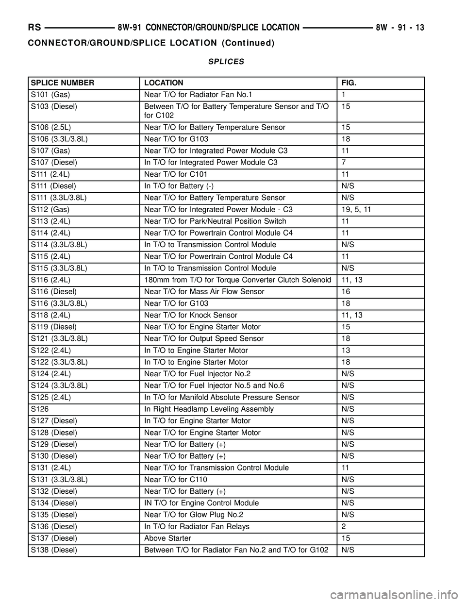
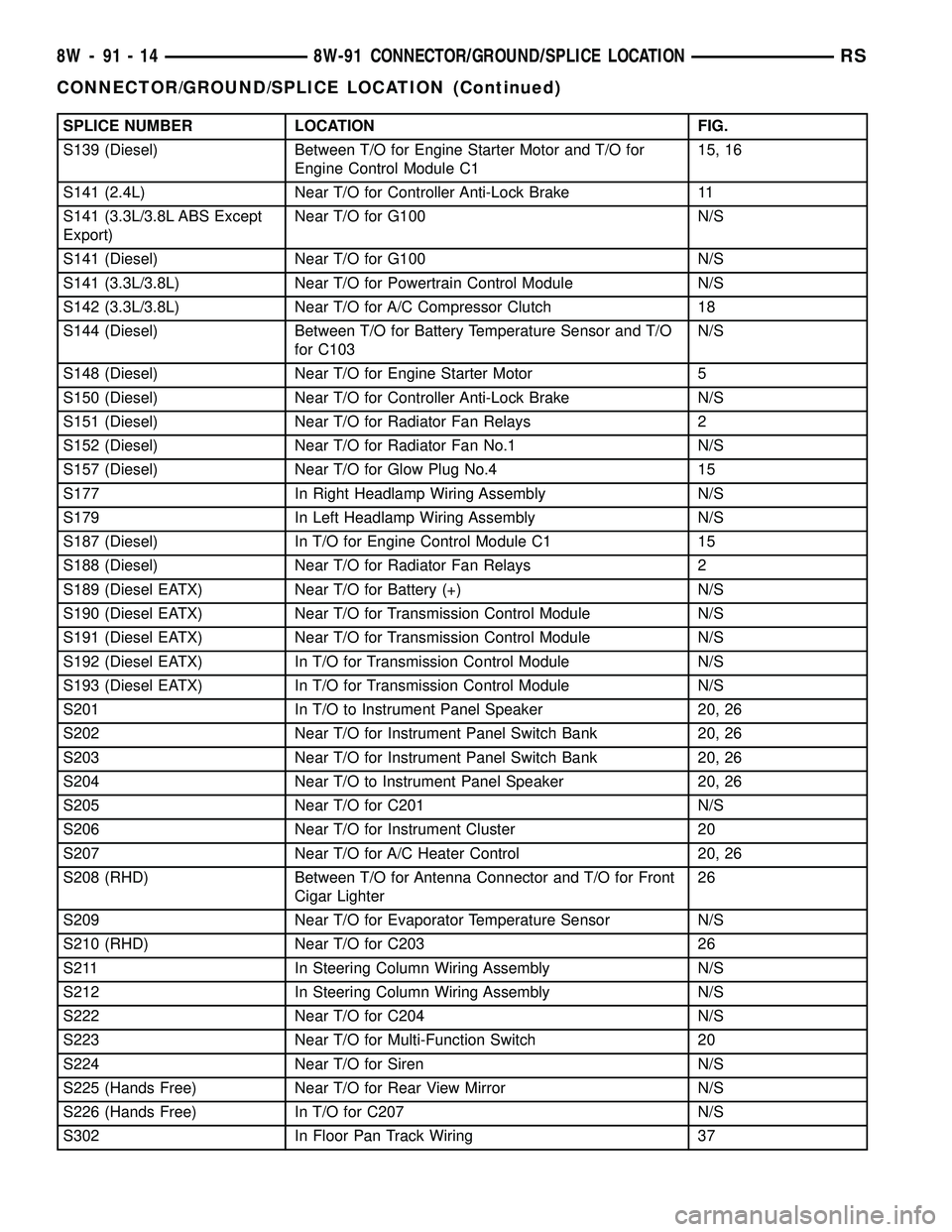
8W-91 CONNECTOR/GROUND/SPLICE LOCATION
TABLE OF CONTENTS
page
CONNECTOR/GROUND/SPLICE LOCATION
DESCRIPTION..........................1
CONNECTOR/GROUND/SPLICE
LOCATION
DESCRIPTION
This section provides illustrations identifying con-
nector, ground, and splice locations in the vehicle.Connector, ground, and splice indexes are provided.
Use the wiring diagrams in each section for connec-
tor, ground, and splice identification. Refer to the
appropriate index for the proper figure number. For
items that are not shown in this section N/S is placed
in the Fig. column.
CONNECTORS
CONNECTOR NAME/NUMBER COLOR LOCATION FIG.
A/C Compressor Clutch LTGY Top of A/C Compressor 10, 11, 15, 17, 18
A/C Pressure Sensor GY At Throttle Body 9, 10, 15, 16, 17
A/C-Heater Control C1 (MTC) BK/RD Rear of Control 20, 23, 25
A/C-Heater Control C2 (MTC) BK/BL Rear of Control 20, 23, 25
Accelerator Pedal Position
Sensor (Diesel)At Accelerator Pedal 42
Adjustable Pedals Module
(Except Export)Near Brake Lamp Switch N/S
Adjustable Pedals Motor On Pedal Support N/S
Adjustable Pedals Relay (Except
Export)Left Side Engine Compartment 6
Adjustable Pedals Sensor On Adjustable Pedals Motor N/S
Adjustable Pedals Switch (Except
Export)Left Side Kick Panel 41
Ambient Temperature Sensor
(Except Base)BK On Radiator Closure Panel 1
Amplifier C1 NAT Right Quarter Panel 48
Amplifier C2 NAT Right Quarter Panel 48
ATC Remote Sensor Above ATC Control N/S
Auto Temp Control C1 NAT Rear of Control 20
Auto Temp Control C2 BK Rear of Control 20
Auto Temp Control C3 (MTX) Rear of Control N/S
Back-Up Lamp Switch BK On Transmission 16
Battery Temperature Sensor BK At Battery N/S
Blower Motor Resistor C1 (MTC) BK Right Side of HVAC N/S
Blower Motor Resistor C2 (MTC) BK Right Side of HVAC N/S
Body Control Module C1 BK Under Left Instrument Panel 41, 42
RS8W-91 CONNECTOR/GROUND/SPLICE LOCATION8W-91-1
Page 1122 of 2339

CONNECTOR NAME/NUMBER COLOR LOCATION FIG.
Passenger Door Courtesy Lamp GY At Lamp 44
Passenger Door Lock Switch BK At Switch 44
Passenger Folding Mirror Relay
(Export)BL Left Kick Panel 7
Passenger Heated Seat Back GN At Seat N/S
Passenger Heated Seat Cushion BK At Seat N/S
Passenger Heated Seat Module GY At Heated Seat N/S
Passenger Power Seat Front
Riser MotorRD Under Seat N/S
Passenger Power Seat Horizontal
MotorBK Under Seat N/S
Passenger Power Seat Rear
Riser MotorRD Under Seat N/S
Passenger Power Seat Recliner
MotorGN Under Seat N/S
Passenger Power Seat Switch GN At Switch N/S
Passenger Power Window Motor RD At Motor 44
Passenger Power Window Switch BK At Switch 44
Passenger Seat Belt Switch
(Occupant Sensing)YL On Seat Harness N/S
Passenger Seat Belt Tensioner On Seat Harness N/S
Passenger Seat Weight Sensor BK Passenger Seat N/S
Power Folding Mirror Switch
(Export)BK Near Steering Column 31
Power Liftgate Module C1 BK Left Quarter 46, 47
Power Liftgate Module C2 Left Quarter 46, 47
Power Liftgate Motor BK Left Quarter 47
Power Mirror Switch BK Rear of Switch 30
Power Outlet (Except Lowline) BK Instrument Panel 20, 23, 25
Power Seat Circuit Breaker GY Under Seat N/S
Powertrain Control Module C1 BK Left Front Engine Compartment 11
Powertrain Control Module C2 OR Left Front Engine Compartment 11
Powertrain Control Module C3 NAT Left Front Engine Compartment 11
Powertrain Control Module C4 GN Left Front Engine Compartment 11
Power Window Circuit Breaker GY Left Side Kick Panel 41 42
Radiator Fan No.1 (Gas) BK Left Side At Motor 1
Radiator Fan No.1 (Diesel) GY Left Side At Motor 1
Radiator Fan No.2 (Gas) BK Right Side At Motor 1, 2
Radiator Fan No.2 (Diesel) GY Right Side At Motor 1, 2
Radiator Fan Relay (Gas) Top of Left Front Frame Rail 1
Radiator Fan Relay No. 1
(Diesel)BL Left Front Engine Compartment 2
Radiator Fan Relay No. 2
(Diesel)BL Left Front Engine Compartment 2
RS8W-91 CONNECTOR/GROUND/SPLICE LOCATION8W-91-9
CONNECTOR/GROUND/SPLICE LOCATION (Continued)
Page 1123 of 2339

CONNECTOR NAME/NUMBER COLOR LOCATION FIG.
Radiator Fan Relay No. 3
(Diesel)BL Left Front Engine Compartment 2
Radio C1 Rear of Radio 20
Radio C2 (CD Changer) Rear of Radio 20
Radio C2 (DVD/CD Changer) Rear of Radio 20
Radio C2 (Hands Free) Rear of Radio 20
Rear A/C-Heater Unit (3 Zone
MTC)LTGN Right Quarter Panel NS
Rear Auto Temp Control Switch
(3 Zone ATC)BK Rear of Switch 50
Rear Blower Front Control Switch
(3 Zone MTC)BK Rear of Switch N/S
Rear Blower Motor Power Module
C1 (3 Zone ATC)RD/BK Right Quarter N/S
Rear Blower Motor Power Module
C2 (3 Zone ATC)BK Right Quarter N/S
Rear Blower Rear Control Switch
C1 (3 Zone MTC)BK Overhead 50
Rear Blower Rear Control Switch
C2 (3 Zone MTC)BK Overhead 50
Rear Dome Lamp (Except
Luxury)GY At Lamp N/S
Rear Intrusion Sensor (United
Kingdom)At Sensor N/S
Rear Mode Motor (3 Zone ATC) GY At Motor N/S
Rear Park Assist Display Module Overhead Console N/S
Rear Park Assist Module Left Quarter Panel 47
Rear Power Outlet GY Left Quarter Panel 47
Rear Temperature Motor (3 Zone
ATC)GY Right Quarter N/S
Rear View Mirror C1 BK At Mirror NS
Rear View Mirror C2 At Mirror N/S
Rear Window Defogger C1 Right Side of Liftgate 49
Rear Window Defogger C2 Left Side of Liftgate 49
Rear Wiper Motor At Motor 49
Recirculation Door Actuator GY Right Side of HVAC N/S
Right B-Pillar Switch (Power
Sliding Door)GY Right B Pillar 39
Right Cinch/Release Motor
(Power Sliding Door)GY Right Sliding Door 45
Right Curtain Airbag Squib Rear of Right Roof Rail 48
Right Cylinder Lock Switch
(Export)BK Right Front Door 44
Right Door Speaker At Speaker N/S
Right Fog Lamp WT At Lamp 3
8W - 91 - 10 8W-91 CONNECTOR/GROUND/SPLICE LOCATIONRS
CONNECTOR/GROUND/SPLICE LOCATION (Continued)
Page 1126 of 2339

SPLICES
SPLICE NUMBER LOCATION FIG.
S101 (Gas) Near T/O for Radiator Fan No.1 1
S103 (Diesel) Between T/O for Battery Temperature Sensor and T/O
for C10215
S106 (2.5L) Near T/O for Battery Temperature Sensor 15
S106 (3.3L/3.8L) Near T/O for G103 18
S107 (Gas) Near T/O for Integrated Power Module C3 11
S107 (Diesel) In T/O for Integrated Power Module C3 7
S111 (2.4L) Near T/O for C101 11
S111 (Diesel) In T/O for Battery (-) N/S
S111 (3.3L/3.8L) Near T/O for Battery Temperature Sensor N/S
S112 (Gas) Near T/O for Integrated Power Module - C3 19, 5, 11
S113 (2.4L) Near T/O for Park/Neutral Position Switch 11
S114 (2.4L) Near T/O for Powertrain Control Module C4 11
S114 (3.3L/3.8L) In T/O to Transmission Control Module N/S
S115 (2.4L) Near T/O for Powertrain Control Module C4 11
S115 (3.3L/3.8L) In T/O to Transmission Control Module N/S
S116 (2.4L) 180mm from T/O for Torque Converter Clutch Solenoid 11, 13
S116 (Diesel) Near T/O for Mass Air Flow Sensor 16
S116 (3.3L/3.8L) Near T/O for G103 18
S118 (2.4L) Near T/O for Knock Sensor 11, 13
S119 (Diesel) Near T/O for Engine Starter Motor 15
S121 (3.3L/3.8L) Near T/O for Output Speed Sensor 18
S122 (2.4L) In T/O to Engine Starter Motor 13
S122 (3.3L/3.8L) In T/O to Engine Starter Motor 18
S124 (2.4L) Near T/O for Fuel Injector No.2 N/S
S124 (3.3L/3.8L) Near T/O for Fuel Injector No.5 and No.6 N/S
S125 (2.4L) In T/O for Manifold Absolute Pressure Sensor N/S
S126 In Right Headlamp Leveling Assembly N/S
S127 (Diesel) In T/O for Engine Starter Motor N/S
S128 (Diesel) Near T/O for Engine Starter Motor N/S
S129 (Diesel) Near T/O for Battery (+) N/S
S130 (Diesel) Near T/O for Battery (+) N/S
S131 (2.4L) Near T/O for Transmission Control Module 11
S131 (3.3L/3.8L) Near T/O for C110 N/S
S132 (Diesel) Near T/O for Battery (+) N/S
S134 (Diesel) IN T/O for Engine Control Module N/S
S135 (Diesel) Near T/O for Glow Plug No.2 N/S
S136 (Diesel) In T/O for Radiator Fan Relays 2
S137 (Diesel) Above Starter 15
S138 (Diesel) Between T/O for Radiator Fan No.2 and T/O for G102 N/S
RS8W-91 CONNECTOR/GROUND/SPLICE LOCATION8W-91-13
CONNECTOR/GROUND/SPLICE LOCATION (Continued)
Page 1127 of 2339

SPLICE NUMBER LOCATION FIG.
S139 (Diesel) Between T/O for Engine Starter Motor and T/O for
Engine Control Module C115, 16
S141 (2.4L) Near T/O for Controller Anti-Lock Brake 11
S141 (3.3L/3.8L ABS Except
Export)Near T/O for G100 N/S
S141 (Diesel) Near T/O for G100 N/S
S141 (3.3L/3.8L) Near T/O for Powertrain Control Module N/S
S142 (3.3L/3.8L) Near T/O for A/C Compressor Clutch 18
S144 (Diesel) Between T/O for Battery Temperature Sensor and T/O
for C103N/S
S148 (Diesel) Near T/O for Engine Starter Motor 5
S150 (Diesel) Near T/O for Controller Anti-Lock Brake N/S
S151 (Diesel) Near T/O for Radiator Fan Relays 2
S152 (Diesel) Near T/O for Radiator Fan No.1 N/S
S157 (Diesel) Near T/O for Glow Plug No.4 15
S177 In Right Headlamp Wiring Assembly N/S
S179 In Left Headlamp Wiring Assembly N/S
S187 (Diesel) In T/O for Engine Control Module C1 15
S188 (Diesel) Near T/O for Radiator Fan Relays 2
S189 (Diesel EATX) Near T/O for Battery (+) N/S
S190 (Diesel EATX) Near T/O for Transmission Control Module N/S
S191 (Diesel EATX) Near T/O for Transmission Control Module N/S
S192 (Diesel EATX) In T/O for Transmission Control Module N/S
S193 (Diesel EATX) In T/O for Transmission Control Module N/S
S201 In T/O to Instrument Panel Speaker 20, 26
S202 Near T/O for Instrument Panel Switch Bank 20, 26
S203 Near T/O for Instrument Panel Switch Bank 20, 26
S204 Near T/O to Instrument Panel Speaker 20, 26
S205 Near T/O for C201 N/S
S206 Near T/O for Instrument Cluster 20
S207 Near T/O for A/C Heater Control 20, 26
S208 (RHD) Between T/O for Antenna Connector and T/O for Front
Cigar Lighter26
S209 Near T/O for Evaporator Temperature Sensor N/S
S210 (RHD) Near T/O for C203 26
S211 In Steering Column Wiring Assembly N/S
S212 In Steering Column Wiring Assembly N/S
S222 Near T/O for C204 N/S
S223 Near T/O for Multi-Function Switch 20
S224 Near T/O for Siren N/S
S225 (Hands Free) Near T/O for Rear View Mirror N/S
S226 (Hands Free) In T/O for C207 N/S
S302 In Floor Pan Track Wiring 37
8W - 91 - 14 8W-91 CONNECTOR/GROUND/SPLICE LOCATIONRS
CONNECTOR/GROUND/SPLICE LOCATION (Continued)
Page 1189 of 2339

²Drill motor with 3M RolocŸ Bristle Disc (white
or yellow) (Fig. 3)
CAUTION: Excessive pressure or high RPM (beyond
the recommended speed), can damage the sealing
surfaces. The mild (white, 120 grit) bristle disc is
recommended. If necessary, the medium (yellow, 80
grit) bristle disc may be used on cast iron surfaces
with care.
STANDARD PROCEDURE - MEASURING
BEARING CLEARANCE USING PLASTIGAGE
Engine crankshaft bearing clearances can be deter-
mined by use of Plastigage or equivalent. The follow-
ing is the recommended procedure for the use of
Plastigage:
(1) Remove oil film from surface to be checked.
Plastigage is soluble in oil.
(2) Place a piece of Plastigage across the entire
width of the bearing shell in the cap approximately
6.35 mm (1/4 in.) off center and away from the oil
holes (Fig. 4). (In addition, suspected areas can be
checked by placing the Plastigage in the suspected
area). Torque the bearing cap/bed plate bolts of the
bearing being checked to the proper specifications.
(3) Remove the bearing cap and compare the
width of the flattened Plastigage with the metric
scale provided on the package. Locate the band clos-
est to the same width. This band shows the amount
of clearance in thousandths of a millimeter. Differ-
ences in readings between the ends indicate the
amount of taper present. Record all readings taken.
Compare the clearance measurements to specsifica-
tions found in the engine specifications table(Refer to9 - ENGINE - SPECIFICATIONS).Plastigage gen-
erally is accompanied by two scales. One scale
is in inches, the other is a metric scale.
NOTE: Plastigage is available in a variety of clear-
ance ranges. Use the most appropriate range for
the specifications you are checking.
(4) Install the proper crankshaft bearings to
achieve the specified bearing clearances.
REMOVAL - ENGINE ASSEMBLY
(1) Perform fuel pressure release procedure (Refer
to 14 - FUEL SYSTEM/FUEL DELIVERY - STAN-
DARD PROCEDURE)
(2) Disconnect battery negative cable.
(3) Remove air cleaner housing and inlet tube.
(4) Disconnect the fuel line from fuel rail. (Refer to
14 - FUEL SYSTEM/FUEL DELIVERY/FUEL LINES
- STANDARD PROCEDURE)
(5) Disconnect all vacuum hoses.
(6) Drain cooling system. (Refer to 7 - COOLING -
STANDARD PROCEDURE)
(7) Remove radiator fans. (Refer to 7 - COOLING/
ENGINE/RADIATOR FAN - REMOVAL)
(8) Remove radiator upper and lower hoses.
NOTE: When the transaxle cooler lines are removed
from the rolled-groove type fittings at the transaxle,
damage to the inner wall of the hose will occur. To
prevent prevent potential leakage, the cooler hoses
must be cut off flush at the transaxle fitting, and a
service cooler hose splice kit must be installed
upon reassembly.
Fig. 3 Proper Tool Usage For Surface Preparation
1 - ABRASIVE PAD
2 - 3M ROLOCŸ BRISTLE DISC
3 - PLASTIC/WOOD SCRAPER
Fig. 4 Plastigage Placed in Lower ShellÐTypical
1 - PLASTIGAGE
9 - 12 ENGINE 2.4LRS
ENGINE 2.4L (Continued)
Page 1193 of 2339

(24) Connect all vacuum lines.
(25) Connect the throttle cables.
(26) Connect the fuel line. (Refer to 14 - FUEL
SYSTEM/FUEL DELIVERY/QUICK CONNECT FIT-
TING - STANDARD PROCEDURE)
(27) Connect radiator lower and upper hoses.
(28) Install radiator fans. (Refer to 7 - COOLING/
ENGINE/RADIATOR FAN - INSTALLATION)
(29) Fill cooling system. (Refer to 7 - COOLING -
STANDARD PROCEDURE)
(30) Connect battery cables.
(31) Install air cleaner and inlet hose.
(32) Fill engine crankcase with proper oil to cor-
rect level.
(33) Start engine and run until operating temper-
ature is reached.
(34) Adjust transmission linkage, if necessary.
SPECIFICATIONS
SPECIFICATIONS - 2.4L ENGINE
GENERAL SPECIFICATIONS
DESCRIPTION SPECIFICATION
Type In-Line OHV, DOHC
Number of
Cylinders4
Firing Order 1-3-4-2
Compression
Ratio9.5:1
Max. Variation
Between
Cylinders25%
Metric Standard
Displacement 2.4 Liters 148 cu. in.
Bore 87.5 mm 3.445 in.
Stroke 101.0 mm 3.976 in.
Compression
Pressure1172-1551 kPa 170-225 psi
CYLINDER BLOCK
DESCRIPTION SPECIFICATIONS
Metric Standard
Cylinder Bore
Diameter87.4924 -
87.5076 mm3.4446 - 3.4452
in.
Out-of-Round
(Max.)0.051 mm 0.002 in.
Taper (Max.) 0.051 mm 0.002 in.
Fig. 9 RIGHT MOUNT TO RAIL AND ENGINE
1 - BOLT - MOUNT TO RAIL 68 N´m (50 ft. lbs.)
2 - BOLT - MOUNT TO ENGINE 54 N´m (40 ft. lbs.)
3 - BOLT - MOUNT TO RAIL (HORIZONTAL) 68 N´m (50 ft. lbs.)
4 - RIGHT ENGINE MOUNT
5 - RIGHT FRAME RAIL
Fig. 10 LEFT MOUNT TO FRAME BRACKET
1 - FRAME BRACKET
2 - FRAME RAIL - LEFT
3 - BOLT
4 - TRANSAXLE MOUNT
9 - 16 ENGINE 2.4LRS
ENGINE 2.4L (Continued)