radiator CHRYSLER CARAVAN 2005 Owner's Manual
[x] Cancel search | Manufacturer: CHRYSLER, Model Year: 2005, Model line: CARAVAN, Model: CHRYSLER CARAVAN 2005Pages: 2339, PDF Size: 59.69 MB
Page 247 of 2339
DIAGNOSIS AND TESTING
DIAGNOSIS AND TESTING - COOLING SYSTEM
PRESSURE CAP TESTING
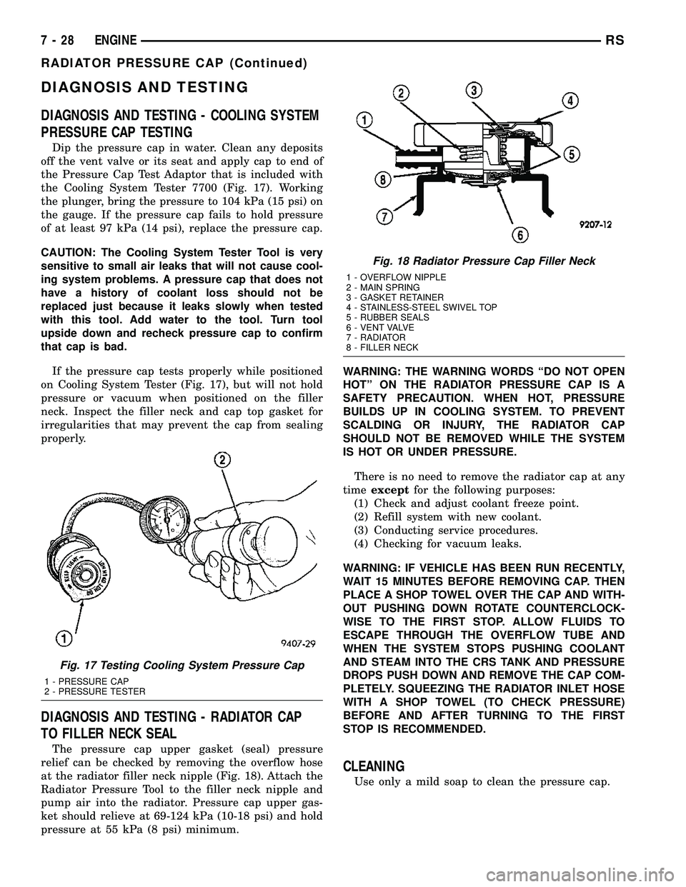
Dip the pressure cap in water. Clean any deposits
off the vent valve or its seat and apply cap to end of
the Pressure Cap Test Adaptor that is included with
the Cooling System Tester 7700 (Fig. 17). Working
the plunger, bring the pressure to 104 kPa (15 psi) on
the gauge. If the pressure cap fails to hold pressure
of at least 97 kPa (14 psi), replace the pressure cap.
CAUTION: The Cooling System Tester Tool is very
sensitive to small air leaks that will not cause cool-
ing system problems. A pressure cap that does not
have a history of coolant loss should not be
replaced just because it leaks slowly when tested
with this tool. Add water to the tool. Turn tool
upside down and recheck pressure cap to confirm
that cap is bad.
If the pressure cap tests properly while positioned
on Cooling System Tester (Fig. 17), but will not hold
pressure or vacuum when positioned on the filler
neck. Inspect the filler neck and cap top gasket for
irregularities that may prevent the cap from sealing
properly.
DIAGNOSIS AND TESTING - RADIATOR CAP
TO FILLER NECK SEAL
The pressure cap upper gasket (seal) pressure
relief can be checked by removing the overflow hose
at the radiator filler neck nipple (Fig. 18). Attach the
Radiator Pressure Tool to the filler neck nipple and
pump air into the radiator. Pressure cap upper gas-
ket should relieve at 69-124 kPa (10-18 psi) and hold
pressure at 55 kPa (8 psi) minimum.WARNING: THE WARNING WORDS ªDO NOT OPEN
HOTº ON THE RADIATOR PRESSURE CAP IS A
SAFETY PRECAUTION. WHEN HOT, PRESSURE
BUILDS UP IN COOLING SYSTEM. TO PREVENT
SCALDING OR INJURY, THE RADIATOR CAP
SHOULD NOT BE REMOVED WHILE THE SYSTEM
IS HOT OR UNDER PRESSURE.
There is no need to remove the radiator cap at any
timeexceptfor the following purposes:
(1) Check and adjust coolant freeze point.
(2) Refill system with new coolant.
(3) Conducting service procedures.
(4) Checking for vacuum leaks.
WARNING: IF VEHICLE HAS BEEN RUN RECENTLY,
WAIT 15 MINUTES BEFORE REMOVING CAP. THEN
PLACE A SHOP TOWEL OVER THE CAP AND WITH-
OUT PUSHING DOWN ROTATE COUNTERCLOCK-
WISE TO THE FIRST STOP. ALLOW FLUIDS TO
ESCAPE THROUGH THE OVERFLOW TUBE AND
WHEN THE SYSTEM STOPS PUSHING COOLANT
AND STEAM INTO THE CRS TANK AND PRESSURE
DROPS PUSH DOWN AND REMOVE THE CAP COM-
PLETELY. SQUEEZING THE RADIATOR INLET HOSE
WITH A SHOP TOWEL (TO CHECK PRESSURE)
BEFORE AND AFTER TURNING TO THE FIRST
STOP IS RECOMMENDED.
CLEANING
Use only a mild soap to clean the pressure cap.
Fig. 17 Testing Cooling System Pressure Cap
1 - PRESSURE CAP
2 - PRESSURE TESTER
Fig. 18 Radiator Pressure Cap Filler Neck
1 - OVERFLOW NIPPLE
2 - MAIN SPRING
3 - GASKET RETAINER
4 - STAINLESS-STEEL SWIVEL TOP
5 - RUBBER SEALS
6 - VENT VALVE
7 - RADIATOR
8 - FILLER NECK
7 - 28 ENGINERS
RADIATOR PRESSURE CAP (Continued)
Page 248 of 2339

INSPECTION
Hold the cap in your hand,top side up(Fig. 19).
The vent valve at the bottom of the cap should open.
If the rubber gasket has swollen, preventing the
valve from opening, replace the cap.
Hold the cleaned cap in your hand,upside down.
If any light can be seen between vent valve and the
rubber gasket, replace the cap.Do not use a
replacement cap that has a spring to hold the
vent shut.
A replacement cap must be of the type designed for
coolant reserve systems. This design ensures coolant
return to the radiator.
RADIATOR FAN
DESCRIPTION
The dual radiator fans are mounted to the back
side of the radiator (Fig. 20). The radiator fan consist
of the fan blade, electric motor and a support shroud
which are all serviced as an assembly.
OPERATION
RADIATOR FAN OPERATION CHART
COOLANT TEMPERATURE A/C PRESSURE TRANSAXLE OIL
TEMPERATURE
Fan
Operation
Speeds:Initial Max Initial Max Initial Max
Fan On: 104ÉC
(220ÉF)110ÉC
(230ÉF) Fan
Speed
Duty-Cycles
(Ramps-up)
from 30% to
99%1,724 Kpa
(250 psi)2,068 Kpa
(300 psi) Fan
Speed
Duty-Cycles
(Ramps-up)
from 30% to
99%96ÉC (204ÉF) 111ÉC (232ÉF)
Fan Speed
Duty Cycles
(Ramps-up)
from 30% to
99%
Fan Off: 101ÉC
(214ÉF)Fan Speed
Duty-Cycles
(Ramps-
down) from
99% to 30%1,710 Kpa
(248 psi)Fan Speed
Duty-Cycles
(Ramps-
down) from
99% to 30%89ÉC (192ÉF) Fan Speed
Duty Cycles
(Ramps-down)
from 99% to
30%
Fig. 19 Cooling System Pressure Cap
1 - OVERFLOW NIPPLE
2 - MAIN SPRING
3 - GASKET RETAINER
4 - STAINLESS-STEEL SWIVEL TOP
5 - RUBBER SEALS
6 - VENT VALVE
7 - RADIATOR
8 - FILLER NECK
RSENGINE7-29
RADIATOR PRESSURE CAP (Continued)
Page 249 of 2339

DIAGNOSIS AND TESTING - RADIATOR FAN MOTOR
RADIATOR FAN DIAGNOSIS CHART
CONDITION POSSIBLE CAUSES CORRECTION
NOISY RADIATOR FAN 1. Fan blade loose. 1. Replace fan assembly. (Refer to
7 - COOLING/ENGINE/RADIATOR
FAN - REMOVAL)
2. Fan blade striking a surrounding
object.2. Locate point of fan blade contact
and repair as necessary.
3. Air obstructions at radiator or A/C
condenser.3. Remove obstructions and/or
clean debris.
4. Electric fan motor defective. 4. Replace fan assembly. (Refer to
7 - COOLING/ENGINE/RADIATOR
FAN - REMOVAL)
ELECTRIC FAN MOTOR DOES
NOT OPERATE1. Fan relay, powertrain control
module (PCM), coolant temperature
sensor, or wiring defective.1. (Refer to Appropriate Diagnostic
Information) Repair as necessary.
2. Defective A/C pressure
transducer.2. (Refer to Appropriate Diagnostic
Information) Repair as necessary.
ELECTRIC RADIATOR FAN
OPERATES ALL THE TIME1. Fan relay, powertrain control
module (PCM), coolant temperature
sensor or wiring defective.1. (Refer to Appropriate Diagnostic
Information) Repair as necessary.
2. Check for low coolant level. 2. Add coolant as necessary.
3. Defective A/C pressure
transducer.3. (Refer to Appropriate Diagnostic
Information) Repair as necessary.
REMOVAL
There are no repairs to be made to the fan or
shroud assembly. If the fan is warped, cracked, or
otherwise damaged, it must be replaced as an assem-
bly (Fig. 20).
(1) Remove the radiator upper crossmember. (Refer
to 23 - BODY/EXTERIOR/GRILLE OPENING REIN-
FORCEMENT - REMOVAL)
(2) Disconnect the radiator fan electrical connec-
tors.
(3) Remove radiator fan(s) retaining screw (Fig.
20).
(4) Remove the radiator fan(s) by lifting upward to
release from mounts.
INSTALLATION
(1) Install the radiator fan(s) into mounts and
attaching clips on the radiator.
(2) Install radiator fan(s) attaching screws (Fig.
20). Tighten to 5 N´m (45 in. lbs.).
(3) Connect the radiator fan(s) electrical connec-
tors.(4) Install the radiator upper support crossmem-
ber. (Refer to 23 - BODY/EXTERIOR/GRILLE OPEN-
ING REINFORCEMENT - INSTALLATION)
Fig. 20 Radiator Fans
1 - SCREWS - RADIATOR FAN ATTACHING
2 - RADIATOR FAN - RIGHT
3 - MOUNT - RIGHT RADIATOR FAN
4 - CLIPS - RADIATOR FAN LOWER
5 - MOUNT - LEFT RADIATOR FAN
6 - RADIATOR FAN - LEFT
7 - 30 ENGINERS
RADIATOR FAN (Continued)
Page 250 of 2339
(5) Install the upper radiator mounts to the cross-
member bolts, if removed. Tighten to 8 N´m (70 in.
lbs.).
(6) Install the radiator upper hose to the support
clip (2.4L engine).
RADIATOR FAN RELAY
DESCRIPTION
The radiator fan relay is a solid state type and is
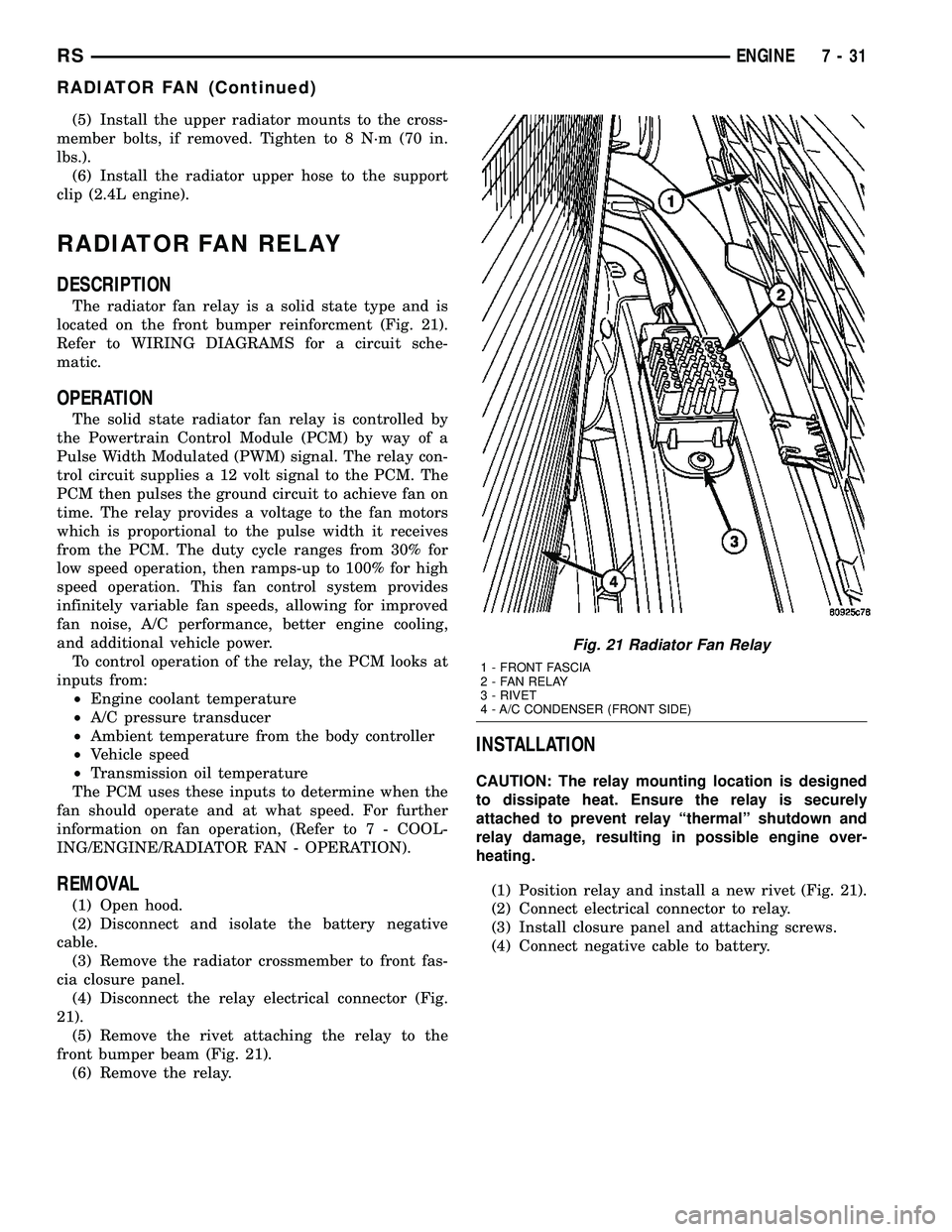
located on the front bumper reinforcment (Fig. 21).
Refer to WIRING DIAGRAMS for a circuit sche-
matic.
OPERATION
The solid state radiator fan relay is controlled by
the Powertrain Control Module (PCM) by way of a
Pulse Width Modulated (PWM) signal. The relay con-
trol circuit supplies a 12 volt signal to the PCM. The
PCM then pulses the ground circuit to achieve fan on
time. The relay provides a voltage to the fan motors
which is proportional to the pulse width it receives
from the PCM. The duty cycle ranges from 30% for
low speed operation, then ramps-up to 100% for high
speed operation. This fan control system provides
infinitely variable fan speeds, allowing for improved
fan noise, A/C performance, better engine cooling,
and additional vehicle power.
To control operation of the relay, the PCM looks at
inputs from:
²Engine coolant temperature
²A/C pressure transducer
²Ambient temperature from the body controller
²Vehicle speed
²Transmission oil temperature
The PCM uses these inputs to determine when the
fan should operate and at what speed. For further
information on fan operation, (Refer to 7 - COOL-
ING/ENGINE/RADIATOR FAN - OPERATION).
REMOVAL
(1) Open hood.
(2) Disconnect and isolate the battery negative
cable.
(3) Remove the radiator crossmember to front fas-
cia closure panel.
(4) Disconnect the relay electrical connector (Fig.
21).
(5) Remove the rivet attaching the relay to the
front bumper beam (Fig. 21).
(6) Remove the relay.
INSTALLATION
CAUTION: The relay mounting location is designed
to dissipate heat. Ensure the relay is securely
attached to prevent relay ªthermalº shutdown and
relay damage, resulting in possible engine over-
heating.
(1) Position relay and install a new rivet (Fig. 21).
(2) Connect electrical connector to relay.
(3) Install closure panel and attaching screws.
(4) Connect negative cable to battery.
Fig. 21 Radiator Fan Relay
1 - FRONT FASCIA
2 - FAN RELAY
3 - RIVET
4 - A/C CONDENSER (FRONT SIDE)
RSENGINE7-31
RADIATOR FAN (Continued)
Page 255 of 2339

(7) Install drive belt shield.
(8) Fill the cooling system. (Refer to 7 - COOLING
- STANDARD PROCEDURE)
WATER PUMP INLET TUBE -
2.4L
DESCRIPTION
The 2.4L engine uses a metal tube to connect the
engine block to the lower radiator hose and heater
return (Fig. 31). The tube has an O-ring for block to
tube sealing and bolts attach the tube to the engine
block.
REMOVAL
(1) Drain the cooling system. (Refer to 7 - COOL-
ING - STANDARD PROCEDURE)
(2) Remove radiator upper hose to access the hose
connections at the inlet tube.
(3) Remove radiator lower (Fig. 7) and heater
hoses from the inlet tube (Fig. 32).
(4) Remove the two fasteners that hold the inlet
tube to the block.
(5) Rotate tube while removing the tube from the
engine block.
INSTALLATION
(1) Inspect the O-ring for damage before installing
the tube into the cylinder block (Fig. 31).
(2) Lube O-ring with coolant and install inlet tube
into the cylinder block opening (Fig. 31).(3) Install the two inlet tube fasteners and tighten
to 12 N´m (105 in. lbs.).
(4) Connect the radiator lower hose (Fig. 7) and
heater hose to inlet tube (Fig. 32).
(5) Install the radiator upper hose.
(6) Fill the cooling system. (Refer to 7 - COOLING
- STANDARD PROCEDURE)
Fig. 30 Water Pump Seal
1 - WATER PUMP HOUSING
2 - SEAL
3 - IMPELLER
Fig. 31 Water Pump Inlet Tube - 2.4L Engine
1 - O-RING
2 - WATER PUMP INLET TUBE
Fig. 32 Water Pump Inlet Tube Hose Connections
1 - WATER PUMP INLET TUBE
2 - HOSE - HEATER RETURN
3 - COOLANT INLET
7 - 36 ENGINERS
WATER PUMP - 3.3/3.8L (Continued)
Page 256 of 2339
WATER PUMP INLET TUBE -
3.3/3.8L
REMOVAL
(1) Drain the cooling system. (Refer to 7 - COOL-
ING - STANDARD PROCEDURE)
(2) Raise vehicle on hoist and remove the belt
splash shield.
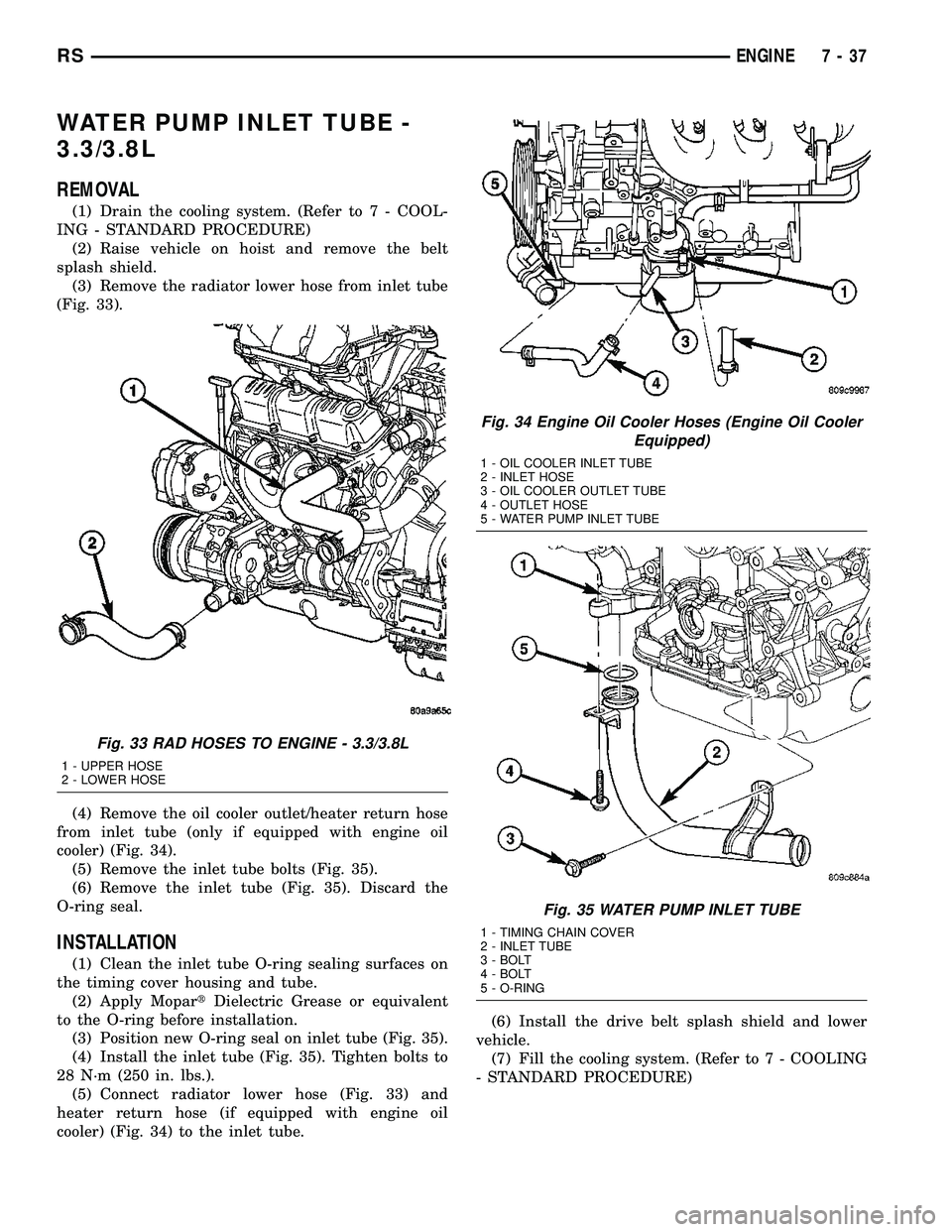
(3) Remove the radiator lower hose from inlet tube
(Fig. 33).
(4) Remove the oil cooler outlet/heater return hose
from inlet tube (only if equipped with engine oil
cooler) (Fig. 34).
(5) Remove the inlet tube bolts (Fig. 35).
(6) Remove the inlet tube (Fig. 35). Discard the
O-ring seal.
INSTALLATION
(1) Clean the inlet tube O-ring sealing surfaces on
the timing cover housing and tube.
(2) Apply MopartDielectric Grease or equivalent
to the O-ring before installation.
(3) Position new O-ring seal on inlet tube (Fig. 35).
(4) Install the inlet tube (Fig. 35). Tighten bolts to
28 N´m (250 in. lbs.).
(5) Connect radiator lower hose (Fig. 33) and
heater return hose (if equipped with engine oil
cooler) (Fig. 34) to the inlet tube.(6) Install the drive belt splash shield and lower
vehicle.
(7) Fill the cooling system. (Refer to 7 - COOLING
- STANDARD PROCEDURE)
Fig. 33 RAD HOSES TO ENGINE - 3.3/3.8L
1 - UPPER HOSE
2 - LOWER HOSE
Fig. 34 Engine Oil Cooler Hoses (Engine Oil Cooler
Equipped)
1 - OIL COOLER INLET TUBE
2 - INLET HOSE
3 - OIL COOLER OUTLET TUBE
4 - OUTLET HOSE
5 - WATER PUMP INLET TUBE
Fig. 35 WATER PUMP INLET TUBE
1 - TIMING CHAIN COVER
2 - INLET TUBE
3 - BOLT
4 - BOLT
5 - O-RING
RSENGINE7-37
Page 258 of 2339
TRANSMISSION OIL COOLER
DESCRIPTION
The automatic transmission cooler is located in the
front of the radiator and behind the front fascia and
is conbined with the A/C condensor. The transmission
cooler is a heat exchanger that allows heat in the
transmission flud to be transferred to the air passing
over the cooler fins.
The Transmission oil cooler/A/C condenser assem-
blly is equipped with quick connect fitting for the
transmission oil cooler lines, a tapping block, for the
receiver/drier, and mounting provisions for the power
steering cooler.
The transmission oil cooler/AC condenser is ser-
viced as an assembly. For removal on vehicles
equipped with 2.4L/3.3L/3.8L engines, (Refer to 24 -
HEATING & AIR CONDITIONING/PLUMBING/A/C
CONDENSER - REMOVAL), vehicles equipped with2.5L/2.8L engines (Refer to 24 - HEATING & AIR
CONDITIONING/PLUMBING/A/C CONDENSER -
REMOVAL). For installation on vehicles equipped
with 2.4L/3.3L/3.8L engines (Refer to 24 - HEATING
& AIR CONDITIONING/PLUMBING/A/C CON-
DENSER - INSTALLATION), and vehicles equipped
with 2.5L/2.8L engines (Refer to 24 - HEATING &
AIR CONDITIONING/PLUMBING/A/C CON-
DENSER - INSTALLATION).
INSPECTION
Inspect all hoses, tubes, clamps and connections for
leaks, cracks, or damage. Replace as necessary. Use
only approved transmission oil cooler hoses that are
molded to fit the space available.
Inspect external coolers for leaks, loose mounts, or
damage. Replace as necessary.
TRANSMISSION OIL COOLER
LINES
REMOVAL
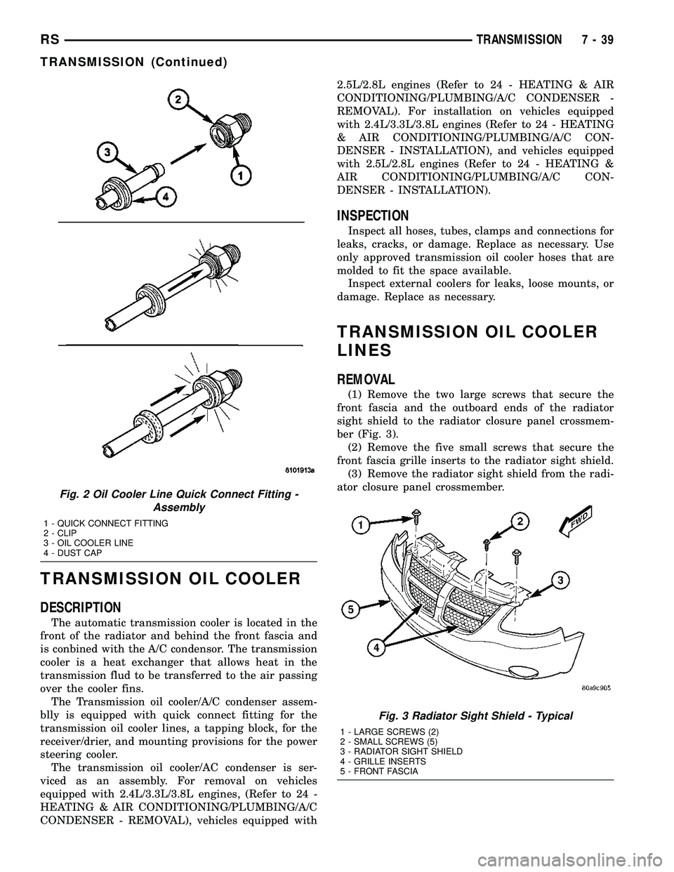
(1) Remove the two large screws that secure the
front fascia and the outboard ends of the radiator
sight shield to the radiator closure panel crossmem-
ber (Fig. 3).
(2) Remove the five small screws that secure the
front fascia grille inserts to the radiator sight shield.
(3) Remove the radiator sight shield from the radi-
ator closure panel crossmember.
Fig. 2 Oil Cooler Line Quick Connect Fitting -
Assembly
1 - QUICK CONNECT FITTING
2 - CLIP
3 - OIL COOLER LINE
4 - DUST CAP
Fig. 3 Radiator Sight Shield - Typical
1 - LARGE SCREWS (2)
2 - SMALL SCREWS (5)
3 - RADIATOR SIGHT SHIELD
4 - GRILLE INSERTS
5 - FRONT FASCIA
RSTRANSMISSION7-39
TRANSMISSION (Continued)
Page 259 of 2339
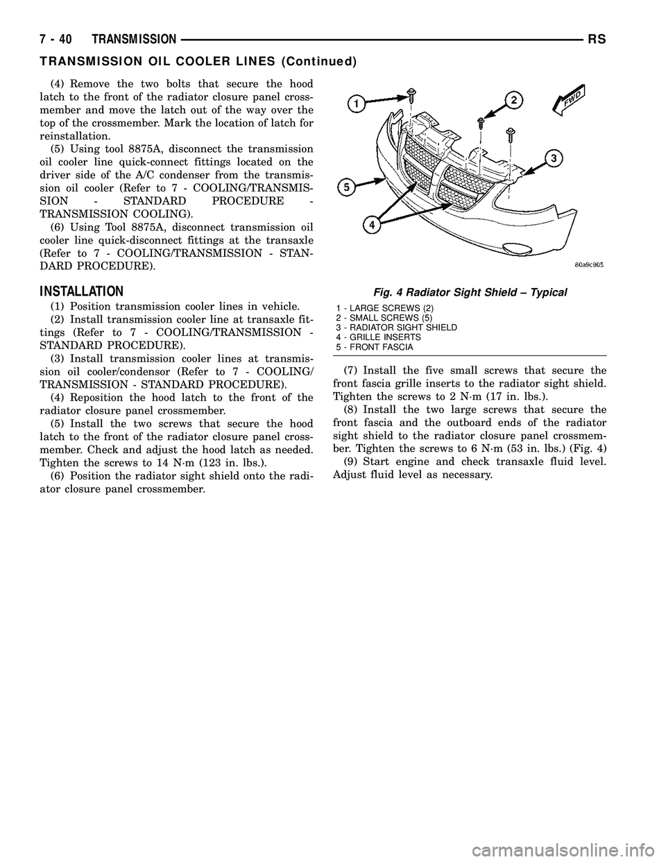
(4) Remove the two bolts that secure the hood
latch to the front of the radiator closure panel cross-
member and move the latch out of the way over the
top of the crossmember. Mark the location of latch for
reinstallation.
(5) Using tool 8875A, disconnect the transmission
oil cooler line quick-connect fittings located on the
driver side of the A/C condenser from the transmis-
sion oil cooler (Refer to 7 - COOLING/TRANSMIS-
SION - STANDARD PROCEDURE -
TRANSMISSION COOLING).
(6) Using Tool 8875A, disconnect transmission oil
cooler line quick-disconnect fittings at the transaxle
(Refer to 7 - COOLING/TRANSMISSION - STAN-
DARD PROCEDURE).
INSTALLATION
(1) Position transmission cooler lines in vehicle.
(2) Install transmission cooler line at transaxle fit-
tings (Refer to 7 - COOLING/TRANSMISSION -
STANDARD PROCEDURE).
(3) Install transmission cooler lines at transmis-
sion oil cooler/condensor (Refer to 7 - COOLING/
TRANSMISSION - STANDARD PROCEDURE).
(4) Reposition the hood latch to the front of the
radiator closure panel crossmember.
(5) Install the two screws that secure the hood
latch to the front of the radiator closure panel cross-
member. Check and adjust the hood latch as needed.
Tighten the screws to 14 N´m (123 in. lbs.).
(6) Position the radiator sight shield onto the radi-
ator closure panel crossmember.(7) Install the five small screws that secure the
front fascia grille inserts to the radiator sight shield.
Tighten the screws to 2 N´m (17 in. lbs.).
(8) Install the two large screws that secure the
front fascia and the outboard ends of the radiator
sight shield to the radiator closure panel crossmem-
ber. Tighten the screws to 6 N´m (53 in. lbs.) (Fig. 4)
(9) Start engine and check transaxle fluid level.
Adjust fluid level as necessary.
Fig. 4 Radiator Sight Shield ± Typical
1 - LARGE SCREWS (2)
2 - SMALL SCREWS (5)
3 - RADIATOR SIGHT SHIELD
4 - GRILLE INSERTS
5 - FRONT FASCIA
7 - 40 TRANSMISSIONRS
TRANSMISSION OIL COOLER LINES (Continued)
Page 363 of 2339
- DIAGNOSIS AND TESTING). If battery connec-
tions and battery charge is OK proceed to Step 2.
(2) Using a voltmeter, test for battery voltage at
both sides of horn fuse 7. If voltage is OK, on both
sides of fuse, proceed to Fuse OK. If voltage is OK,
on one side of fuse, the fuse is blown, proceed to Step
3.
(3) Using a suitable ammeter in place of the fuse,
test amperage draw of the horn circuit. If amperage
draw is greater than 20 amps without the horn
switch depressed, a grounded circuit exists between
the fuse and the horn relay. Proceed to Step 4. If
amperage draw is greater than 20 amps with the
horn switch depressed, a grounded circuit exists
between the horn relay and the horn. Proceed to step
Step 5.
(4) Remove the horn relay from the IPM. If the
amperage draw drops to 0 amps, the horn switch or
circuit is shorted. If the amperage draw does not
drop to 0 amps, repair short at the IPM.
(5) Disengage a wire connector from one of the
horns. If amperage drops and the connected horn
sounds, replace the faulty horn. If amperage does not
drop with both horns disconnected and the horn
switch depressed, proceed to Step 6.
(6) Using a continuity tester, with the horns dis-
connected test continuity of the X2 cavity of the horn
relay to ground. If continuity is detected, the circuit
is grounded between the Junction Block and the
horns. Locate and repair pinched harness.
FUSE OK
(1) Remove the horn relay from the intelligent
power module.
(2) Using a continuity tester, Depress horn switch
and test continuity from the X3 cavity of the horn
relay to ground.
(a) If continuity is detected, proceed to Step 3.
(b) If NO continuity, proceed to Step 4.
(3) Using a suitable jumper wire, jump across the
fuse F62 cavity and the X2 cavity of the horn relay in
the Junction Block.
(a) If the horn sounds, replace the horn relay.
(b) If the horn does not sound, proceed to Step 4.
(4) Remove airbag trim cover from steering wheel.
Refer to ELECTRICAL, RESTRAINTS.
(5) Test continuity across horn switch connectors
with horn switch depressed.
(a) If continuity is detected, repair open circuit
between the relay and the horn switch.
(b) If NO continuity, replace airbag trim cover.
(6) Install horn relay into intelligent power mod-
ule.
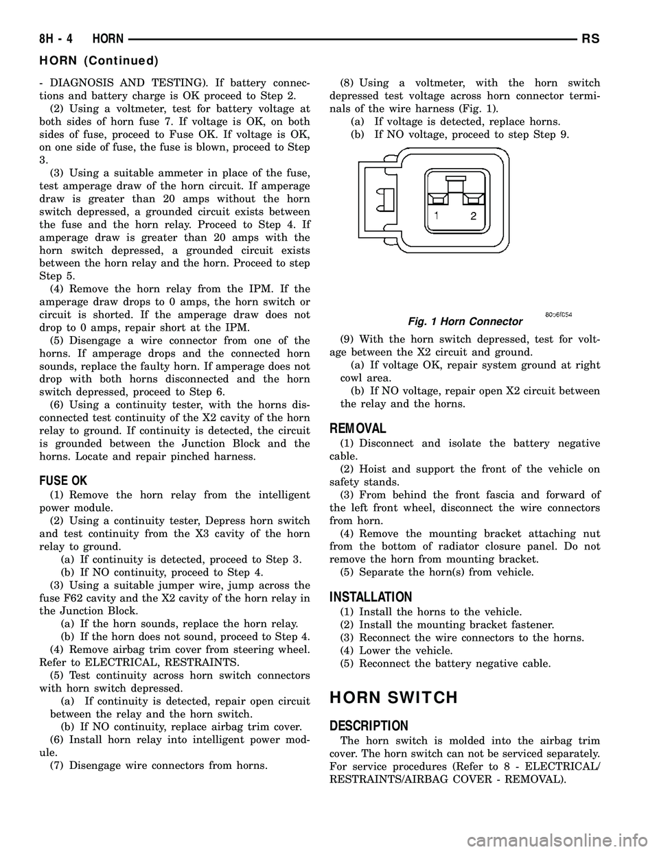
(7) Disengage wire connectors from horns.(8) Using a voltmeter, with the horn switch
depressed test voltage across horn connector termi-
nals of the wire harness (Fig. 1).
(a) If voltage is detected, replace horns.
(b) If NO voltage, proceed to step Step 9.
(9) With the horn switch depressed, test for volt-
age between the X2 circuit and ground.
(a) If voltage OK, repair system ground at right
cowl area.
(b) If NO voltage, repair open X2 circuit between
the relay and the horns.
REMOVAL
(1) Disconnect and isolate the battery negative
cable.
(2) Hoist and support the front of the vehicle on
safety stands.
(3) From behind the front fascia and forward of
the left front wheel, disconnect the wire connectors
from horn.
(4) Remove the mounting bracket attaching nut
from the bottom of radiator closure panel. Do not
remove the horn from mounting bracket.
(5) Separate the horn(s) from vehicle.
INSTALLATION
(1) Install the horns to the vehicle.
(2) Install the mounting bracket fastener.
(3) Reconnect the wire connectors to the horns.
(4) Lower the vehicle.
(5) Reconnect the battery negative cable.
HORN SWITCH
DESCRIPTION
The horn switch is molded into the airbag trim
cover. The horn switch can not be serviced separately.
For service procedures (Refer to 8 - ELECTRICAL/
RESTRAINTS/AIRBAG COVER - REMOVAL).
Fig. 1 Horn Connector
8H - 4 HORNRS
HORN (Continued)
Page 421 of 2339
STANDARD PROCEDURE
SETTING TRANSMITTER CODES
(1) Turn off the engine.
(2) Erase the codes by pressing the two outside
buttons. Release the buttons when the display con-
firms the operation (about 20 seconds).
(3) Choose one of the three buttons to train. Place
the hand-held transmitter within one inch of the uni-
versal transmitter and push the buttons on both
transmitters.
(4) Release both buttons. Your universal transmit-
ter is now ªtrainedº. To train the other buttons,
repeat Step 3 and Step 4. Be sure to keep your hand-
held transmitter in case you need to retrain the uni-
versal transmitter.
ERASING TRANSMITTER CODES
To erase the universal transmitter codes, simply
hold down the two outside buttons until the display
confirms the operation.
NOTE: Individual channels cannot be erased. Eras-
ing the transmitter codes will erase ALL pro-
grammed codes.
REMOVAL
(1) For the universal transmitter removal proce-
dure, (Refer to 8 - ELECTRICAL/OVERHEAD CON-
SOLE/COMPASS/MINI-TRIP COMPUTER -
REMOVAL.
AMBIENT TEMP SENSOR
DESCRIPTION
Ambient air temperature is monitored by the over-
head console through ambient temperature messages
received from the Powertrain Control Module (PCM)
over the Programmable Communications Interface
(PCI) data bus circuit. The PCM receives a hard
wired input from the ambient temperature sensor.
The ambient temperature sensor is a variable resis-
tor mounted to a bracket that is secured with a screw
to the right side of the headlamp mounting module
grille opening, behind the radiator grille and in front
of the engine compartment.
For additional information on the PCM, (Refer to 8
- ELECTRICAL/ELECTRONIC CONTROL MOD-
ULES/POWERTRAIN CONTROL MODULE -
DESCRIPTION).
OPERATION
The ambient temperature sensor is a variable
resistor that operates on a five-volt reference signal
sent by the Powertrain Control Module (PCM). The
resistance in the sensor changes as temperature
changes, changing the temperature sensor signal cir-
cuit voltage to the PCM. Based upon the resistance
in the sensor, the PCM senses a specific voltage on
the temperature sensor signal circuit, which it is pro-
grammed to correspond to a specific temperature.
The PCM then sends the proper ambient tempera-
ture messages to the Electronic Vehicle Information
Center (EVIC)/Compass Mini-Trip Computer (CMTC)
over the Programmable Communication Interface
(PCI) data bus.
The thermometer function is supported by the
ambient temperature sensor, a wiring circuit, the
PCM, the PCI data bus, and the Electronics module.
If any portion of the ambient temperature sensor cir-
cuit fails, the PCM will self-diagnose the circuit.
The ambient temperature sensor circuit can also be
diagnosed manually (Refer to 8 - ELECTRICAL/
OVERHEAD CONSOLE/AMBIENT TEMP SENSOR
- DIAGNOSIS AND TESTING - AMBIENT TEM-
PERATURE SENSOR CIRCUIT). If the temperature
sensor and circuit are confirmed to be OK, but the
temperature display is inoperative or incorrect,
(Refer to 8 - ELECTRICAL/OVERHEAD CONSOLE -
DIAGNOSIS AND TESTING) to determine the cause.
For complete circuit diagrams, refer to the appropri-
ate wiring information.
DIAGNOSIS AND TESTING
AMBIENT TEMPERATURE SENSOR
(1) Turn the ignition switch to the Off position.
Disconnect and isolate the battery negative cable.
Disconnect the ambient temperature sensor wire har-
ness connector.
(2) Measure the resistance of the ambient temper-
ature sensor. At room temperature (approx. 68ÉF),
the sensor resistance should be between 10-13 Kilo-
hms. The sensor resistance should be between these
two values at 68ÉF. If the resistance is out of range
replace the ambient temperature sensor.
AMBIENT TEMPERATURE SENSOR CIRCUIT
(1) Turn the ignition switch to the Off position.
Disconnect and isolate the battery negative cable.
Disconnect the ambient temperature sensor wire har-
ness connector and the Powertrain Control Module
(PCM) wire harness connector.
8M - 12 OVERHEAD CONSOLERS
UNIVERSAL TRANSMITTER (Continued)