remote control CHRYSLER CARAVAN 2005 Workshop Manual
[x] Cancel search | Manufacturer: CHRYSLER, Model Year: 2005, Model line: CARAVAN, Model: CHRYSLER CARAVAN 2005Pages: 2339, PDF Size: 59.69 MB
Page 1418 of 2339
WARNING: THE AIR BAG SYSTEM IS A SENSITIVE,
COMPLEX ELECTRO-MECHANICAL UNIT. BEFORE
ATTEMPTING TO DIAGNOSE, REMOVE OR INSTALL
THE AIR BAG SYSTEM COMPONENTS YOU MUST
FIRST DISCONNECT AND ISOLATE THE BATTERY
NEGATIVE (GROUND) CABLE. THEN WAIT TWO
MINUTES FOR THE SYSTEM CAPACITOR TO DIS-
CHARGE. FAILURE TO DO SO COULD RESULT IN
ACCIDENTAL DEPLOYMENT OF THE AIR BAG AND
POSSIBLE PERSONAL INJURY. THE FASTENERS,
SCREWS, AND BOLTS, ORIGINALLY USED FOR
THE AIR BAG COMPONENTS, HAVE SPECIAL
COATINGS AND ARE SPECIFICALLY DESIGNED
FOR THE AIR BAG SYSTEM. THEY MUST NEVER
BE REPLACED WITH ANY SUBSTITUTES. ANYTIME
A NEW FASTENER IS NEEDED, REPLACE WITH
THE CORRECT FASTENERS PROVIDED IN THE
SERVICE PACKAGE OR FASTENERS LISTED IN
THE PARTS BOOKS.
WARNING: SAFETY GOGGLES SHOULD BE WORN
AT ALL TIMES WHEN WORKING ON STEERING
COLUMNS.
CAUTION: Disconnect negative (ground) cable from
the battery before servicing any column compo-
nent.
CAUTION: Do not attempt to remove the pivot pins
to disassemble the tilting mechanism. Damage will
occur.
DIAGNOSIS AND TESTING - STEERING
COLUMN
For diagnosis of conditions relating to the steering
column, (Refer to 19 - STEERING - DIAGNOSIS
AND TESTING).
REMOVAL
NOTE: Before proceeding, (Refer to 19 - STEERING/
COLUMN - WARNING)(Refer to 8 - ELECTRICAL/RE-
STRAINTS/DRIVER AIRBAG - REMOVAL).
(1) Make sure the front wheels of the vehicle are
in the STRAIGHT AHEAD position before beginning
the column removal procedure.
(2) Disconnect and isolate the negative (ground)
cable from the battery. Wait at least two minutes for
the airbag system reserve capacitor to discharge
before beginning any steering column, instrument
panel, or airbag system/component service.WARNING: WHEN AN UNDEPLOYED AIRBAG IS TO
BE REMOVED FROM THE VEHICLE, FIRST DISCON-
NECT AND ISOLATE THE BATTERY NEGATIVE
(GROUND) CABLE. ALLOW THE AIRBAG SYSTEM
RESERVE CAPACITOR TO DISCHARGE FOR TWO
MINUTES BEFORE BEGINNING ANY AIRBAG SYS-
TEM OR COMPONENT SERVICE. PERSONAL
INJURY MAY RESULT IF THIS PROCEDURE IS NOT
FOLLOWED.
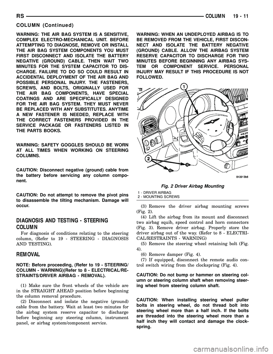
(3) Remove the driver airbag mounting screws
(Fig. 2).
(4) Lift the airbag from its mount and disconnect
two airbag squib, speed control and horn connectors
(Fig. 3). Remove driver airbag. Properly store the
driver airbag out of the way. (Refer to 8 - ELECTRI-
CAL/RESTRAINTS - WARNING)
(5) Remove the steering wheel retaining bolt (Fig.
4).
(6) Remove damper (Fig. 4).
(7) If equipped, disconnect the remote audio con-
trol switch wiring from the clockspring (Fig. 4).
CAUTION: Do not bump or hammer on steering col-
umn or steering column shaft when removing steer-
ing wheel from steering column shaft.
CAUTION: When installing steering wheel puller
bolts in steering wheel, do not thread bolt into
steering wheel more than a half inch. If the bolts
are threaded into the steering wheel more than a
half inch they will contact and damage the clock-
spring.
Fig. 2 Driver Airbag Mounting
1 - DRIVER AIRBAG
2 - MOUNTING SCREWS
RSCOLUMN19-11
COLUMN (Continued)
Page 1419 of 2339
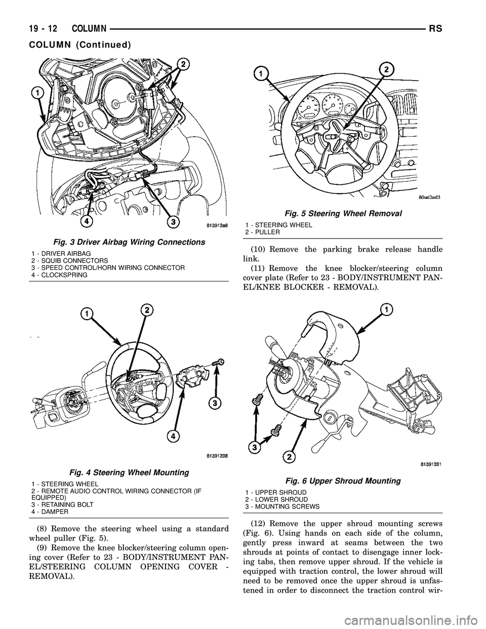
(8) Remove the steering wheel using a standard
wheel puller (Fig. 5).
(9) Remove the knee blocker/steering column open-
ing cover (Refer to 23 - BODY/INSTRUMENT PAN-
EL/STEERING COLUMN OPENING COVER -
REMOVAL).(10) Remove the parking brake release handle
link.
(11) Remove the knee blocker/steering column
cover plate (Refer to 23 - BODY/INSTRUMENT PAN-
EL/KNEE BLOCKER - REMOVAL).
(12) Remove the upper shroud mounting screws
(Fig. 6). Using hands on each side of the column,
gently press inward at seams between the two
shrouds at points of contact to disengage inner lock-
ing tabs, then remove upper shroud. If the vehicle is
equipped with traction control, the lower shroud will
need to be removed once the upper shroud is unfas-
tened in order to disconnect the traction control wir-
Fig. 3 Driver Airbag Wiring Connections
1 - DRIVER AIRBAG
2 - SQUIB CONNECTORS
3 - SPEED CONTROL/HORN WIRING CONNECTOR
4 - CLOCKSPRING
Fig. 4 Steering Wheel Mounting
1 - STEERING WHEEL
2 - REMOTE AUDIO CONTROL WIRING CONNECTOR (IF
EQUIPPED)
3 - RETAINING BOLT
4 - DAMPER
Fig. 5 Steering Wheel Removal
1 - STEERING WHEEL
2 - PULLER
Fig. 6 Upper Shroud Mounting
1 - UPPER SHROUD
2 - LOWER SHROUD
3 - MOUNTING SCREWS
19 - 12 COLUMNRS
COLUMN (Continued)
Page 1424 of 2339
(19) Position the lower shroud on the column (Fig.
8). Install the lower shroud mounting screw. Tighten
the screw to 2 N´m (17 in. lbs.) torque.
(20) If equipped with adjustable pedals, Connect
the wiring connector for the switch (Fig. 7) to the col-
umn wiring harness.
(21) Position the upper shroud on top of the lower
shroud and snap it into place. Install the upper
shroud mounting screws (Fig. 6). Tighten the screws
to 2 N´m (17 in. lbs.) torque.
(22) Inspect shroud mating surfaces for excessive
gaps and correct as necessary.
(23) Install the cluster trim bezel (Refer to 23 -
BODY/INSTRUMENT PANEL/CLUSTER BEZEL -
INSTALLATION).
(24) Install the knee blocker/steering column cover
plate. (Refer to 23 - BODY/INSTRUMENT PANEL/
KNEE BLOCKER - INSTALLATION)
(25) Install the parking brake handle link.
(26) Install the knee blocker/steering column open-
ing cover. (Refer to 23 - BODY/INSTRUMENT PAN-
EL/STEERING COLUMN OPENING COVER -
INSTALLATION)
(27) Align the splines and install the steering
wheel on the steering column shaft(Refer to 19 -
STEERING/COLUMN/STEERING WHEEL -
INSTALLATION).
(28) Install the damper over the steering column
shaft (Fig. 4).
(29) Install the steering wheel retaining bolt (Fig.
4). Tighten the bolt to 61 N´m (45 ft. lbs.) torque.
(30) If the steering wheel is equipped with remote
audio controls, connect the wiring connector to the
clockspring (Fig. 4).
(31) Connect the two squib connectors to the
driver airbag (Fig. 3). The connectors are color coded
to avoid connector mix-up.
(32) Connect the speed control and horn connector
to the clockspring (Fig. 3).
(33) Install the airbag to the steering wheel.
Install the driver airbag mounting screws (Fig. 2).
Tighten screws to 10 N´m (90 in. lbs.) torque.
(34) Connect the battery negative (ground) cable to
battery post following special Diagnosis And Testing
procedure. (Refer to 8 - ELECTRICAL/RESTRAINTS
- DIAGNOSIS AND TESTING)
(35) Check operation of all steering column
mounted components.
(36) Road test vehicle to ensure proper operation
of steering.SPECIFICATIONS
COLUMN FASTENER TORQUE
DESCRIPTION N´mFt.
Lbs.In.
Lbs.
Driver Airbag Mounting Screws 10 Ð 90
Multi-Function Switch Mounting
Housing Set-Screw14 Ð 124
Shroud Attaching Screws - Fixed 3 Ð 23
Shroud Attaching Screws -
Lower/Upper2Ð17
SKIM Attaching Screw 4 Ð 30
Steering Column Coupling Pinch
Bolt28 Ð 250
Steering Column Mounting Nuts 12 Ð 105
Steering Wheel Retaining Bolt 61 45 Ð
IGNITION SWITCH
REMOVAL
The ignition switch attaches to the lock cylinder
housing on the end opposite the lock cylinder (Fig.
20). For ignition switch terminal and circuit identifi-
cation, refer to the appropriate wiring information.
The wiring information includes wiring diagrams,
proper wire and connector repair procedures, further
details on wire harness routing and retention, as well
as pin-out and location views for the various wire
harness connectors, splices and grounds.
(1) Disconnect negative cable from battery.
Fig. 20 Ignition SwitchÐViewed From Below
Column
1 - IGNITION SWITCH
2 - LOCK CYLINDER HOUSING
3 - RETAINING TABS
RSCOLUMN19-17
COLUMN (Continued)
Page 1431 of 2339
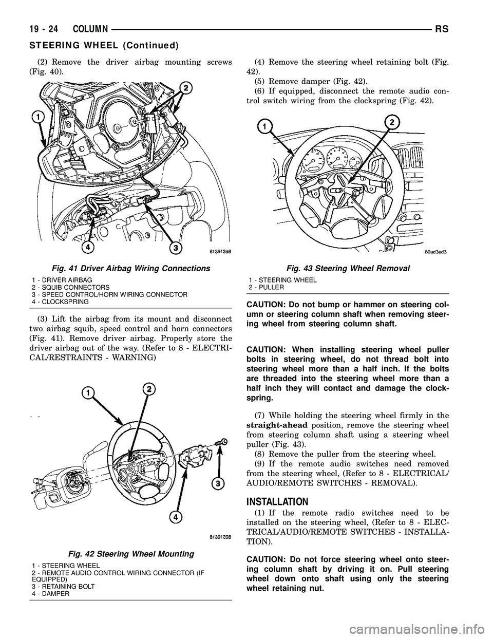
(2) Remove the driver airbag mounting screws
(Fig. 40).
(3) Lift the airbag from its mount and disconnect
two airbag squib, speed control and horn connectors
(Fig. 41). Remove driver airbag. Properly store the
driver airbag out of the way. (Refer to 8 - ELECTRI-
CAL/RESTRAINTS - WARNING)(4) Remove the steering wheel retaining bolt (Fig.
42).
(5) Remove damper (Fig. 42).
(6) If equipped, disconnect the remote audio con-
trol switch wiring from the clockspring (Fig. 42).
CAUTION: Do not bump or hammer on steering col-
umn or steering column shaft when removing steer-
ing wheel from steering column shaft.
CAUTION: When installing steering wheel puller
bolts in steering wheel, do not thread bolt into
steering wheel more than a half inch. If the bolts
are threaded into the steering wheel more than a
half inch they will contact and damage the clock-
spring.
(7) While holding the steering wheel firmly in the
straight-aheadposition, remove the steering wheel
from steering column shaft using a steering wheel
puller (Fig. 43).
(8) Remove the puller from the steering wheel.
(9) If the remote audio switches need removed
from the steering wheel, (Refer to 8 - ELECTRICAL/
AUDIO/REMOTE SWITCHES - REMOVAL).
INSTALLATION
(1) If the remote radio switches need to be
installed on the steering wheel, (Refer to 8 - ELEC-
TRICAL/AUDIO/REMOTE SWITCHES - INSTALLA-
TION).
CAUTION: Do not force steering wheel onto steer-
ing column shaft by driving it on. Pull steering
wheel down onto shaft using only the steering
wheel retaining nut.
Fig. 41 Driver Airbag Wiring Connections
1 - DRIVER AIRBAG
2 - SQUIB CONNECTORS
3 - SPEED CONTROL/HORN WIRING CONNECTOR
4 - CLOCKSPRING
Fig. 42 Steering Wheel Mounting
1 - STEERING WHEEL
2 - REMOTE AUDIO CONTROL WIRING CONNECTOR (IF
EQUIPPED)
3 - RETAINING BOLT
4 - DAMPER
Fig. 43 Steering Wheel Removal
1 - STEERING WHEEL
2 - PULLER
19 - 24 COLUMNRS
STEERING WHEEL (Continued)
Page 1432 of 2339
(2) Feed and route wiring from clockspring
through upper access hole in steering wheel.
(3) Align master serrations in steering wheel with
omitted spline on steering column shaft (at 12 o'clock
position). Slide the steering wheel onto the steering
column shaft by hand (Fig. 42). Use care not to pinch
any wiring.
NOTE: Before installing the damper on the steering
wheel, inspect the damper to ensure the rubber iso-
lator on the damper is not deteriorated or damaged.
If the damper is installed with a damaged isolator, a
buzz, squeak or rattle condition may develop.
(4) Install the damper on the steering wheel (Fig.
42).
(5) Install the steering wheel retaining bolt.
Tighten the steering wheel retaining bolt to 61 N´m
(45 ft. lbs.) torque.(6) If the steering wheel is equipped with remote
audio controls, connect the wiring connector to the
clockspring (Fig. 42).
(7) Connect the airbag squib wiring connectors to
the airbag and the horn and speed control switch
connector to the clockspring (Fig. 41).
(8) Install the driver airbag in the steering wheel
(Fig. 40). Install and tighten the airbag attaching
screws to 10 N´m (90 in. lbs.) torque.
(9) Connect the battery negative (ground) cable to
battery post following special Diagnosis And Testing
procedure. (Refer to 8 - ELECTRICAL/RESTRAINTS
- DIAGNOSIS AND TESTING)
(10) Check operation of all steering wheel mounted
components.
(11) Road test vehicle to ensure proper operation of
steering.
RSCOLUMN19-25
STEERING WHEEL (Continued)
Page 1458 of 2339
(4) Route hose (with cooler attached) up toward
reservoir avoiding tight bends or kinking.
(5) Start steering gear end of hose into gear port.
Do not tighten hose tube nut at this time.
(6) Attach return hose tubes to suspension cradle
crossmember using routing clamp and bolt (Fig. 21).
Tighten clamp bolt to 23 N´m (200 in. lbs.) torque.
(7) Install the power steering fluid cooler on the
cradle crossmember reinforcement (Fig. 24). Install
the mounting bolts and tighten to 11 N´m (100 in.
lbs.). When installing mounting bolts, include pres-
sure hose routing clamp.
(8) Tighten hose tube nut at power steering gear
port to 31 N´m (275 in. lbs.) torque.
(9) Install front emissions vapor canister. (Refer to
25 - EMISSIONS CONTROL/EVAPORATIVE EMIS-
SIONS/VAPOR CANISTER - INSTALLATION)
(10) Lower vehicle.
(11) Install return hose tube into retainer on ABS
bracket (Fig. 21). Close the bracket.
(12) Install return hose onto reservoir (Fig. 22).
Slide the hose clamp into position on fluid reservoir
and attach it.Be sure hose clamp in installed
past bead on fluid reservoir fitting.
(13) Fill and bleed power steering system using
the Power Steering Pump Initial Operation Proce-
dure. (Refer to 19 - STEERING/PUMP - STANDARD
PROCEDURE)
(14) Inspect system for leaks.
HOSE - POWER STEERING
SUPPLY
REMOVAL
REMOVAL - 2.4L ENGINE
(1) Remove filler cap from power steering fluid res-
ervoir.
(2) Using a siphon pump, remove as much power
steering fluid as possible from the power steering
fluid reservoir.
(3) Raise vehicle. (Refer to LUBRICATION &
MAINTENANCE/HOISTING - STANDARD PROCE-
DURE)
(4) Remove hose clamp securing supply hose to
power steering pump, then remove supply hose from
pump fitting.
(5) Lower vehicle.
(6) Remove hose clamp attaching power steering
fluid supply hose to power steering fluid reservoir,
then remove supply hose.
(7) Remove the power steering fluid supply hose
from the vehicle.
REMOVAL - 3.3L/3.8L ENGINE
NOTE: Before proceeding, review all WARNINGS
and CAUTIONS. (Refer to 19 - STEERING/PUMP -
WARNING)(Refer to 19 - STEERING/PUMP - CAU-
TION)
(1) Remove cap from power steering fluid reser-
voir.
(2) Using a siphon pump, remove as much power
steering fluid as possible from power steering fluid
reservoir.
(3) Place an oil drain pan under vehicle to catch
any draining power steering fluid.
(4) Remove clamp attaching supply hose to power
steering fluid reservoir. Disconnect hose from reser-
voir (Fig. 22).
(5) Pull upward on hose routing clip releasing it
from bracket on cylinder head cover (Fig. 22).
NOTE: It may be necessary to remove air cleaner
housing to gain greater access to supply hose at
power steering pump. (Refer to 9 - ENGINE/AIR
INTAKE SYSTEM/AIR CLEANER HOUSING -
REMOVAL)
(6) Remove clamp attaching supply hose to power
steering pump. Disconnect hose from pump and
remove from vehicle (Fig. 22).
INSTALLATION
INSTALLATION - 2.4L ENGINE
(1) Install and correctly route power steering fluid
supply hose from remote fluid reservoir to power
steering pump.
(2) Install fluid supply hose onto power steering
fluid reservoir. Install hose clamp.Be sure hose
clamp is installed past bead on fluid reservoir
fitting.
(3) Raise vehicle. (Refer to LUBRICATION &
MAINTENANCE/HOISTING - STANDARD PROCE-
DURE)
(4) Install power steering fluid supply hose on
power steering pump supply fitting. Install hose
clamp.Be sure hose clamp is installed past bead
on pump fitting.
(5) Lower vehicle.
(6) Fill and bleed power steering system using
Power Steering Pump Initial Operation Procedure.
(Refer to 19 - STEERING/PUMP - STANDARD PRO-
CEDURE)
(7) Inspect system for leaks.
RSPUMP19-51
HOSE - POWER STEERING RETURN (Continued)
Page 1767 of 2339
OPERATION
The Tire Pressure Monitoring (TPM) system uses
radio and sensor technology to monitor tire air pres-
sure levels. Sensors, mounted to each road wheel as
part of the valve stem, transmit a low frequency indi-
cating their individual pressure to a receiver located
in the Wireless Control Module (WCM) portion of the
Sentry Key Remote Electronic Entry Module
(SKREEM). These transmissions occur approximately
once every minute at speeds over 20 mph (32 km/h).
The Tire Pressure Monitoring system remains active
even if no tire pressure related message is displayed.
The sensors lay dormant (Park Mode), then wake
and start transmitting (Drive Mode) when the vehicle
first reaches speeds over 20 mph (32 km/h). Once the
wheels stop rotating for a period of approximately 30
minutes, the sensors shut down until again awaken.
Although not transmitting as when in Drive Mode,
while in Park Mode, the sensors still transmit
approximately once every 13 hours to let the receiver
know air pressure status at that time.
The receiver only receives information from the
four rotating tires. A fifth sensor may be located in
the spare tire wheel, depending on vehicle options.
Although this fifth sensor may be present, it does not
broadcast any information because it does not rotate.
When the system detects that a tire is going low,
below the Low Pressure (lamp) ON Threshold (See
following table), the driver is alerted to the situation.
The Base system illuminates an indicator lamp,
warning the driver of a pressure issue and sounds an
audible chime. In equipped with the Premium sys-
tem, the information is also displayed on the Elec-
tronic Vehicle Information Center (EVIC).
Once pressure in the suspect tire raises above the
Low Pressure (lamp) OFF Threshold, the lamp will
go out and the system returns to normal.
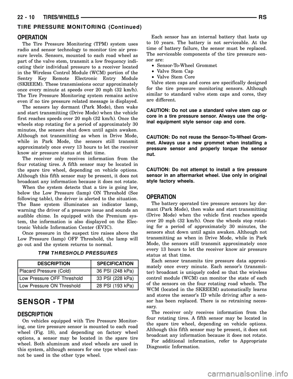
TPM THRESHOLD PRESSURES
DESCRIPTION SPECIFICATION
Placard Pressure (Cold) 36 PSI (248 kPa)
Low Pressure OFF Threshold 33 PSI (228 kPa)
Low Pressure ON Threshold 28 PSI (193 kPa)
SENSOR - TPM
DESCRIPTION
On vehicles equipped with Tire Pressure Monitor-
ing, one tire pressure sensor is mounted to each road
wheel (Fig. 18), and depending on factory wheel
options, a sensor may be located in the spare tire
wheel. Both aluminum and steel wheels are used in
this system, although sensors for one type wheel can-
not be used in the other type wheel.Each sensor has an internal battery that lasts up
to 10 years. The battery is not serviceable. At the
time of battery failure, the sensor must be replaced.
The serviceable components of the tire pressure sen-
sor are:
²Sensor-To-Wheel Grommet
²Valve Stem Cap
²Valve Stem Core
Valve stem caps and cores are specifically designed
for the tire pressure monitoring sensors. Although
similar to standard valve stem caps and cores, they
are different.
CAUTION: Do not use a standard valve stem cap or
core in a tire pressure sensor. Always use the orig-
inal equipment style sensor cap and core.
CAUTION: Do not reuse the Sensor-To-Wheel Grom-
met. Always use a new grommet when installing a
pressure sensor and properly torque the sensor
nut.
CAUTION: Do not attempt to install a tire pressure
sensor in an aftermarket wheel. Use only in original
style factory wheels.
OPERATION
The battery operated tire pressure sensors lay dor-
mant (Park Mode), then wake and start transmitting
(Drive Mode) when the vehicle first reaches speeds
over 20 mph (32 km/h). Once the wheels stop rotat-
ing for a period of approximately 30 minutes, the
sensors shut down until again awaken. Although not
transmitting as when in Drive Mode, while in Park
Mode, the sensors still transmit approximately once
every 13 hours to let the receiver know air pressure
status at that time.
Each sensor transmits tire pressure data approxi-
mately once every minute. Each sensor's (transmit-
ter) broadcast is uniquely coded so that the wireless
control module (WCM) can monitor the state of each
of the sensors on the four rotating road wheels. The
WCM (located in the SKREEM) automatically learns
and stores the sensor's ID while driving after a sen-
sor has been replaced. There is no retraining neces-
sary.
The receiver only receives information from the
four rotating tires. A fifth sensor may be located in
the spare tire wheel, depending on vehicle options.
Although this fifth sensor may be present, it does not
broadcast any information because it does not rotate.
For additional information, refer to Appropriate
Diagnostic Information.
22 - 10 TIRES/WHEELSRS
TIRE PRESSURE MONITORING (Continued)
Page 1791 of 2339
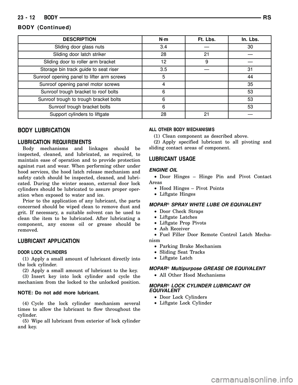
DESCRIPTION N´m Ft. Lbs. In. Lbs.
Sliding door glass nuts 3.4 Ð 30
Sliding door latch striker 28 21 Ð
Sliding door to roller arm bracket 12 9 Ð
Storage bin track guide to seat riser 3.5 Ð 31
Sunroof opening panel to lifter arm screws 5 44
Sunroof opening panel motor screws 4 35
Sunroof trough bracket to roof bolts 6 53
Sunroof trough to trough bracket bolts 6 53
Sunroof trough bracket bolts 6 53
Support cylinders to liftgate 28 21 Ð
BODY LUBRICATION
LUBRICATION REQUIREMENTS
Body mechanisms and linkages should be
inspected, cleaned, and lubricated, as required, to
maintain ease of operation and to provide protection
against rust and wear. When performing other under
hood services, the hood latch release mechanism and
safety catch should be inspected, cleaned, and lubri-
cated. During the winter season, external door lock
cylinders should be lubricated to assure proper oper-
ation when exposed to water and ice.
Prior to the application of any lubricant, the parts
concerned should be wiped clean to remove dust and
grit. If necessary, a suitable solvent can be used to
clean the item to be lubricated. After lubricating a
component, any excess oil or grease should be
removed.
LUBRICANT APPLICATION
DOOR LOCK CYLINDERS
(1) Apply a small amount of lubricant directly into
the lock cylinder.
(2) Apply a small amount of lubricant to the key.
(3) Insert key into lock cylinder and cycle the
mechanism from the locked to the unlocked position.
NOTE: Do not add more lubricant.
(4) Cycle the lock cylinder mechanism several
times to allow the lubricant to flow throughout the
cylinder.
(5) Wipe all lubricant from exterior of lock cylinder
and key.ALL OTHER BODY MECHANISMS
(1) Clean component as described above.
(2) Apply specified lubricant to all pivoting and
sliding contact areas of component.
LUBRICANT USAGE
ENGINE OIL
²Door Hinges ± Hinge Pin and Pivot Contact
Areas
²Hood Hinges ± Pivot Points
²Liftgate Hinges
MOPARTSPRAY WHITE LUBE OR EQUIVALENT
²Door Check Straps
²Liftgate Latches
²Liftgate Prop Pivots
²Ash Receiver
²Fuel Filler Door Remote Control Latch Mecha-
nism
²Parking Brake Mechanism
²Sliding Seat Tracks
²Liftgate Latch
MOPARTMultipurpose GREASE OR EQUIVALENT
²All Other Hood Mechanisms
MOPARTLOCK CYLINDER LUBRICANT OR
EQUIVALENT
²Door Lock Cylinders
²Liftgate Lock Cylinder
23 - 12 BODYRS
BODY (Continued)
Page 2194 of 2339
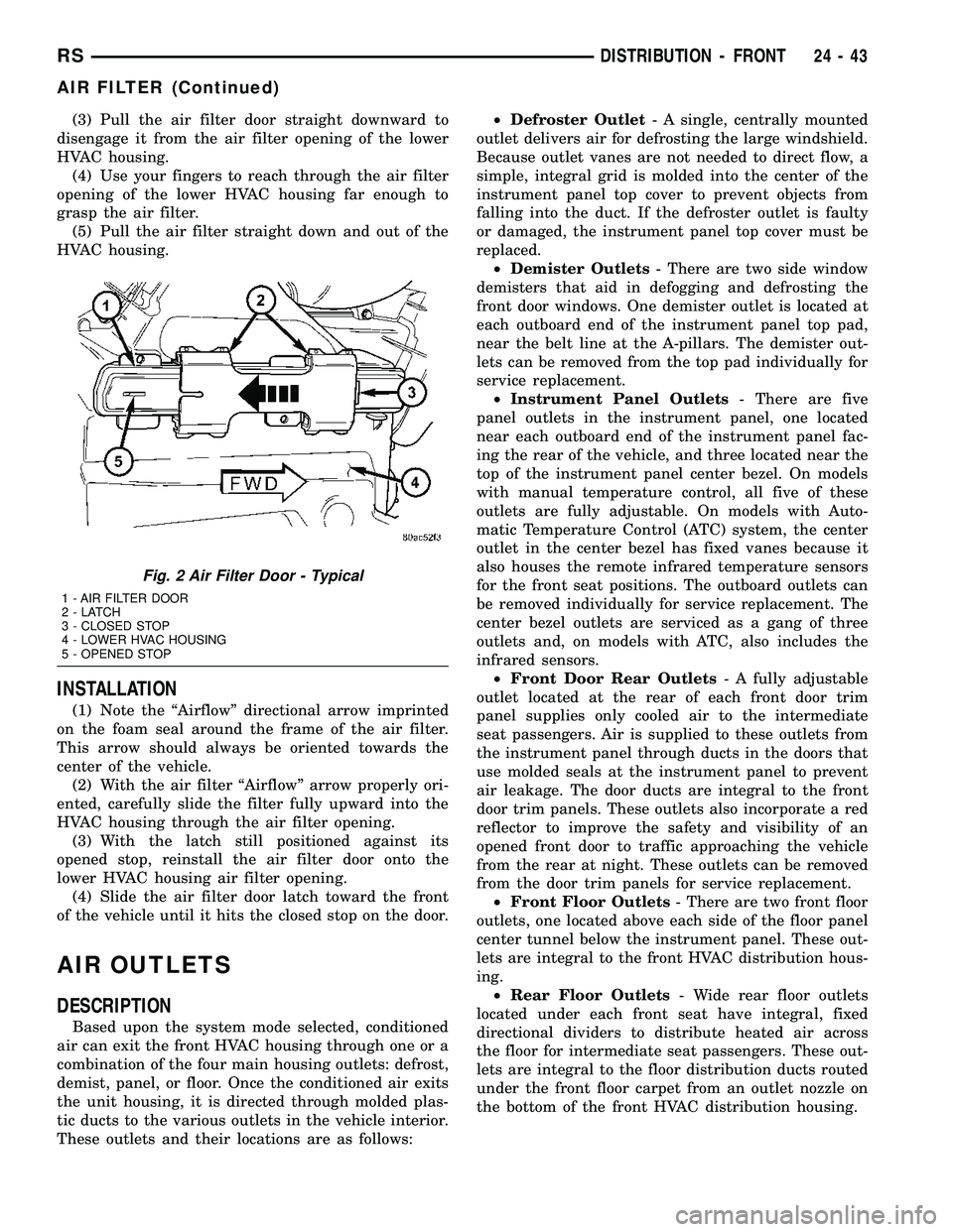
(3) Pull the air filter door straight downward to
disengage it from the air filter opening of the lower
HVAC housing.
(4) Use your fingers to reach through the air filter
opening of the lower HVAC housing far enough to
grasp the air filter.
(5) Pull the air filter straight down and out of the
HVAC housing.
INSTALLATION
(1) Note the ªAirflowº directional arrow imprinted
on the foam seal around the frame of the air filter.
This arrow should always be oriented towards the
center of the vehicle.
(2) With the air filter ªAirflowº arrow properly ori-
ented, carefully slide the filter fully upward into the
HVAC housing through the air filter opening.
(3) With the latch still positioned against its
opened stop, reinstall the air filter door onto the
lower HVAC housing air filter opening.
(4) Slide the air filter door latch toward the front
of the vehicle until it hits the closed stop on the door.
AIR OUTLETS
DESCRIPTION
Based upon the system mode selected, conditioned
air can exit the front HVAC housing through one or a
combination of the four main housing outlets: defrost,
demist, panel, or floor. Once the conditioned air exits
the unit housing, it is directed through molded plas-
tic ducts to the various outlets in the vehicle interior.
These outlets and their locations are as follows:²Defroster Outlet- A single, centrally mounted
outlet delivers air for defrosting the large windshield.
Because outlet vanes are not needed to direct flow, a
simple, integral grid is molded into the center of the
instrument panel top cover to prevent objects from
falling into the duct. If the defroster outlet is faulty
or damaged, the instrument panel top cover must be
replaced.
²Demister Outlets- There are two side window
demisters that aid in defogging and defrosting the
front door windows. One demister outlet is located at
each outboard end of the instrument panel top pad,
near the belt line at the A-pillars. The demister out-
lets can be removed from the top pad individually for
service replacement.
²Instrument Panel Outlets- There are five
panel outlets in the instrument panel, one located
near each outboard end of the instrument panel fac-
ing the rear of the vehicle, and three located near the
top of the instrument panel center bezel. On models
with manual temperature control, all five of these
outlets are fully adjustable. On models with Auto-
matic Temperature Control (ATC) system, the center
outlet in the center bezel has fixed vanes because it
also houses the remote infrared temperature sensors
for the front seat positions. The outboard outlets can
be removed individually for service replacement. The
center bezel outlets are serviced as a gang of three
outlets and, on models with ATC, also includes the
infrared sensors.
²Front Door Rear Outlets- A fully adjustable
outlet located at the rear of each front door trim
panel supplies only cooled air to the intermediate
seat passengers. Air is supplied to these outlets from
the instrument panel through ducts in the doors that
use molded seals at the instrument panel to prevent
air leakage. The door ducts are integral to the front
door trim panels. These outlets also incorporate a red
reflector to improve the safety and visibility of an
opened front door to traffic approaching the vehicle
from the rear at night. These outlets can be removed
from the door trim panels for service replacement.
²Front Floor Outlets- There are two front floor
outlets, one located above each side of the floor panel
center tunnel below the instrument panel. These out-
lets are integral to the front HVAC distribution hous-
ing.
²Rear Floor Outlets- Wide rear floor outlets
located under each front seat have integral, fixed
directional dividers to distribute heated air across
the floor for intermediate seat passengers. These out-
lets are integral to the floor distribution ducts routed
under the front floor carpet from an outlet nozzle on
the bottom of the front HVAC distribution housing.
Fig. 2 Air Filter Door - Typical
1 - AIR FILTER DOOR
2-LATCH
3 - CLOSED STOP
4 - LOWER HVAC HOUSING
5 - OPENED STOP
RSDISTRIBUTION - FRONT24-43
AIR FILTER (Continued)
Page 2195 of 2339
REMOVAL
FRONT CENTER BEZEL OUTLETS
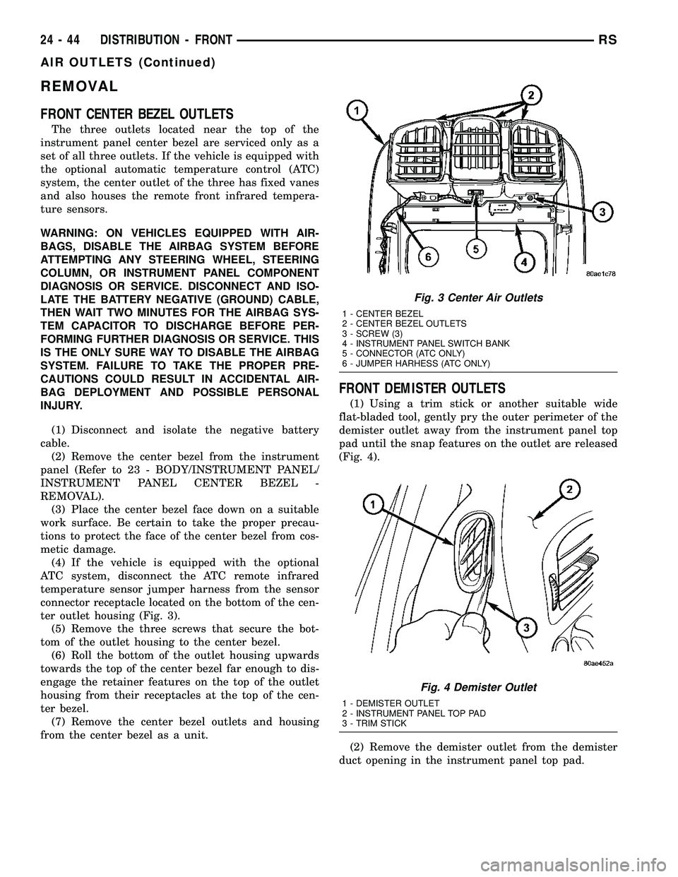
The three outlets located near the top of the
instrument panel center bezel are serviced only as a
set of all three outlets. If the vehicle is equipped with
the optional automatic temperature control (ATC)
system, the center outlet of the three has fixed vanes
and also houses the remote front infrared tempera-
ture sensors.
WARNING: ON VEHICLES EQUIPPED WITH AIR-
BAGS, DISABLE THE AIRBAG SYSTEM BEFORE
ATTEMPTING ANY STEERING WHEEL, STEERING
COLUMN, OR INSTRUMENT PANEL COMPONENT
DIAGNOSIS OR SERVICE. DISCONNECT AND ISO-
LATE THE BATTERY NEGATIVE (GROUND) CABLE,
THEN WAIT TWO MINUTES FOR THE AIRBAG SYS-
TEM CAPACITOR TO DISCHARGE BEFORE PER-
FORMING FURTHER DIAGNOSIS OR SERVICE. THIS
IS THE ONLY SURE WAY TO DISABLE THE AIRBAG
SYSTEM. FAILURE TO TAKE THE PROPER PRE-
CAUTIONS COULD RESULT IN ACCIDENTAL AIR-
BAG DEPLOYMENT AND POSSIBLE PERSONAL
INJURY.
(1) Disconnect and isolate the negative battery
cable.
(2) Remove the center bezel from the instrument
panel (Refer to 23 - BODY/INSTRUMENT PANEL/
INSTRUMENT PANEL CENTER BEZEL -
REMOVAL).
(3) Place the center bezel face down on a suitable
work surface. Be certain to take the proper precau-
tions to protect the face of the center bezel from cos-
metic damage.
(4) If the vehicle is equipped with the optional
ATC system, disconnect the ATC remote infrared
temperature sensor jumper harness from the sensor
connector receptacle located on the bottom of the cen-
ter outlet housing (Fig. 3).
(5) Remove the three screws that secure the bot-
tom of the outlet housing to the center bezel.
(6) Roll the bottom of the outlet housing upwards
towards the top of the center bezel far enough to dis-
engage the retainer features on the top of the outlet
housing from their receptacles at the top of the cen-
ter bezel.
(7) Remove the center bezel outlets and housing
from the center bezel as a unit.
FRONT DEMISTER OUTLETS
(1) Using a trim stick or another suitable wide
flat-bladed tool, gently pry the outer perimeter of the
demister outlet away from the instrument panel top
pad until the snap features on the outlet are released
(Fig. 4).
(2) Remove the demister outlet from the demister
duct opening in the instrument panel top pad.
Fig. 3 Center Air Outlets
1 - CENTER BEZEL
2 - CENTER BEZEL OUTLETS
3 - SCREW (3)
4 - INSTRUMENT PANEL SWITCH BANK
5 - CONNECTOR (ATC ONLY)
6 - JUMPER HARHESS (ATC ONLY)
Fig. 4 Demister Outlet
1 - DEMISTER OUTLET
2 - INSTRUMENT PANEL TOP PAD
3 - TRIM STICK
24 - 44 DISTRIBUTION - FRONTRS
AIR OUTLETS (Continued)