remote control CHRYSLER CARAVAN 2005 User Guide
[x] Cancel search | Manufacturer: CHRYSLER, Model Year: 2005, Model line: CARAVAN, Model: CHRYSLER CARAVAN 2005Pages: 2339, PDF Size: 59.69 MB
Page 449 of 2339

POWER MIRRORS
TABLE OF CONTENTS
page page
POWER MIRRORS
DESCRIPTION.........................26
OPERATION...........................26
DIAGNOSIS AND TESTING
POWER MIRRORS....................27
AUTOMATIC DAY / NIGHT MIRROR
DESCRIPTION.........................28
OPERATION...........................28
DIAGNOSIS AND TESTING
AUTOMATIC DAY / NIGHT MIRROR.......28
POWER FOLDAWAY MIRROR SWITCH -
EXPORT
DESCRIPTION.........................29OPERATION...........................29
REMOVAL.............................29
INSTALLATION.........................30
REMOTE SWITCH
DIAGNOSIS AND TESTING
REMOTE SWITCH.....................30
REMOVAL.............................30
INSTALLATION.........................30
SIDEVIEW MIRROR
REMOVAL.............................30
POWER MIRRORS
DESCRIPTION
If equipped with power mirrors, the control switch
is located on the instrument panel to the left of the
headlamp switch.
OPERATION
The power mirrors are connected to battery feed at
all times. Each mirror head contains two electric
motors, two drive mechanisms, an electric heating
element, and the mirror glass. If the vehicle is
equipped with the optional memory system, the
driver side mirror head also contains both a horizon-
tal and a vertical motor position sensor. One motor
and drive controls mirror up-and-down movement,
and the other controls right-and-left movement.An optional driver side outside electrochromic mir-
ror is able to automatically change its reflectance
level. This mirror is controlled by the circuitry of the
automatic day/night inside rear view mirror. A thin
layer of electrochromic material between two pieces
of conductive glass make up the face of the mirror.
Two photocell sensors on the inside rear view mirror
are used to monitor light levels and adjust the reflec-
tance of both the inside and driver side outside mir-
rors. This change in reflectance helps to reduce the
glare of headlamps approaching the vehicle from the
rear. (Refer to 8 - ELECTRICAL/POWER MIRRORS/
AUTOMATIC DAY / NIGHT MIRROR - DESCRIP-
TION) for more information on this system.
The motors which operate the mirrors are part of
the mirror assembly and cannot be serviced sepa-
rately.
8N - 26 POWER MIRRORSRS
Page 455 of 2339

(Refer to 8 - ELECTRICAL/HEATED SEATS -
DESCRIPTION) for more information on the heated
seat option. (Refer to 8 - ELECTRICAL/POWER
SEATS - DESCRIPTION - MEMORY SEAT SYS-
TEM) for more information on the memory seat sys-
tem.
The power seat system includes the following com-
ponents:
²Power seat recliners
²Power seat switches
²Power seat tracks
²Circuit breaker
The power seat system with memory and heated
seat options includes the following components:
²Power seat recliner
²Power seat switch
²Power seat track.
²Memory Seat Mirror Module (MSMM)
²Memory set switch
²Heated Seat Module (HSM)
²Heated seat switch
²Electronic Vehicle Information Center (EVIC)
MEMORY SYSTEM
The memory system is able to store and recall the
driver side power seat positions (including the power
recliner position), power adjustable pedal positions
and the driver outside mirror position for two driv-
ers. On vehicles equipped with a factory radio, the
memory system is also able to store and recall radio
station presets for two drivers. The memory system
also will store and recall the last station listened to
for each driver, even if it is not one of the preset sta-
tions.
The memory system will automatically return to
its preset settings when the corresponding numbered
button of the memory switch is depressed, or when
the doors are unlocked using the corresponding
Remote Keyless Entry (RKE) transmitter. A customer
programmable feature of the memory system allows
the RKE recall of memory features to be disabled, if
desired. This programmable feature is internal in the
Electronic Vehicle Information Center (EVIC) mod-
ule, which is located in the overhead console.
A Memory Seat Mirror Module (MSMM) is used to
control and integrate the many electronic functions
and features included in the memory seat and mirror
systems.
The memory system includes the following compo-
nents:
²Memory Seat Mirror Module (MSMM)
²Memory set switch
²Position potentiometers on the driver outside
side view mirror
²Position potentiometers on the power adjustable
pedal motor²Position potentiometers on the driver side power
seat track and power seat recliner motors
²Electronic Vehicle Information Center (EVIC)
²Radio receiver (if PCI data bus capable)
Certain functions of the memory system rely upon
resources shared with other electronic modules in the
vehicle over the Programmable Communications
Interface (PCI) data bus network. Initial diagnosis of
these electronic modules or the PCI data bus network
requires the use of a DRBIIItor equivalent scan tool
and the proper Diagnostic Procedures information. If
this method does not prove conclusive, the proper
wiring schematics and the service manual diagnostic
information are required.
The other electronic modules that may affect mem-
ory system operation are:
²Body Control Module (BCM)- (Refer to 8 -
ELECTRICAL/ELECTRONIC CONTROL MOD-
ULES/BODY CONTROL/CENTRAL TIMER MODUL
- DESCRIPTION) for additional information.
²Powertrain Control Module (PCM)- (Refer
to 8 - ELECTRICAL/ELECTRONIC CONTROL
MODULES/POWERTRAIN CONTROL MODULE -
DESCRIPTION) for additional information.
²Transmission Control Module (TCM)- (Refer
to 8 - ELECTRICAL/ELECTRONIC CONTROL
MODULES/TRANSMISSION CONTROL MODULE -
DESCRIPTION) for additional information.
(Refer to 8 - ELECTRICAL/HEATED SEATS -
DESCRIPTION) for additional information on the
heated seat system. (Refer to 8 - ELECTRICAL/
POWER LOCKS - DESCRIPTION) for additional
information on the RKE system.
OPERATION
POWER SEAT SYSTEM
The power seat system receives battery current
through fuse #22 in the Integrated Power Module
(IPM) and a circuit breaker under the front seats,
regardless of the ignition switch position.
When a power seat switch control knob or knobs
are actuated, a battery feed and a ground path are
applied through the switch contacts to the appropri-
ate power seat track adjuster motor. The selected
adjuster motor operates to move the seat track
through its drive unit in the selected direction until
the switch is released, or until the travel limit of the
seat track is reached. When the switch is moved in
the opposite direction, the battery feed and ground
path to the motor are reversed through the switch
contacts. This causes the adjuster motor to run in the
opposite direction.
No power seat switch should be held applied in any
direction after the seat track has reached its travel
limit. The power seat adjuster motor each contain a
8N - 32 POWER SEAT SYSTEMRS
POWER SEAT SYSTEM (Continued)
Page 493 of 2339

experienced, exit the vehicle for fresh air until
the irritation ceases. If irritation continues, see
a physician.
Do not use a replacement airbag that is not in
the original packaging. This may result in
improper deployment, personal injury, or
death.
The factory installed fasteners, screws and
bolts used to fasten airbag components have a
special coating and are specifically designed
for the airbag system. Do not use substitute fas-
teners. Use only original equipment fasteners
listed in the parts catalog when fastener
replacement is required.
During, and following, any child restraint
anchor service, due to impact event or vehicle
repair, carefully inspect all mounting hard-
ware, tether straps, and anchors for proper
installation, operation, or damage. If a child
restraint anchor is found damaged in any way,
the anchor must be replaced. Failure to do this
may result in personal injury or death.
Deployed and nondeployed airbags may or
may not have live pyrotechnic material within
the airbag inflator. Do not dispose of driver/
passenger/seat/curtain/knee blocker airbags or
seat belt tensioners unless you are sure of com-
plete deployment. Refer to the Hazardous Sub-
stance Control System for proper disposal.
Dispose of deployed airbags and tensioners
consistent with state, provincial, local, and fed-
eral regulations.
After any airbag component testing or ser-
vice, do not connect the battery negative cable
(Refer to 8 - ELECTRICAL/RESTRAINTS -
DIAGNOSIS AND TESTING - AIRBAG SYSTEM).
Personal injury or death may result if the sys-
tem test is not performed first.
If the vehicle is equipped with the Occupant
Classification System (OCS), do not connect the
battery negative cable before performing the
OCS Verification Test using the scan tool and
the appropriate diagnostic information. Per-
sonal injury or death may result if the system
test is not performed properly.
Never replace both the Occupant Restraint
Controller (ORC) and the Occupant Classifica-
tion Module (OCM) at the same time. If both
require replacement, replace one, then perform
the Airbag System test (Refer to 8 - ELECTRI-
CAL/RESTRAINTS - DIAGNOSIS AND TESTING
- AIRBAG SYSTEM) before replacing the other.
Both the ORC and the OCM store Occupant
Classification System (OCS) calibration data,
which they transfer to one another when one of
them is replaced. If both are replaced at thesame time, an irreversible fault will be set in
both modules and the OCS may malfunction
and cause personal injury or death.
DIAGNOSIS AND TESTING - AIRBAG SYSTEM
(1) With the battery negative remote cable discon-
nected, connect the scan tool to the Data Link Con-
nector (DLC).
(2) Turn the ignition key to the ON position, then
exit vehicle with the scan tool.
(3) After checking that no one is inside the vehicle,
connect the battery negative remote terminal.
(4) Read and record theACTIVEDiagnostic Trou-
ble Code (DTC) data.
(5) Read and record anySTOREDDTC's.
(6) Refer to the proper diagnostic information if
any DTC's are found in Step 4 and Step 5.
(7) If the airbag warning lamp either fails to light,
or goes ON and stays ON, there is a system malfunc-
tion. To test the airbag warning lamp (bulb) opera-
tion in the cluster (Refer to 8 - ELECTRICAL/
INSTRUMENT CLUSTER - DIAGNOSIS AND
TESTING). Refer to the proper diagnostic informa-
tion for any other system problems.
STANDARD PROCEDURE
STANDARD PROCEDURE - HANDLING
AIRBAGS
DEPLOYED AIRBAG
WARNING: The vehicle interior may contain a very
small amount of powder, a by-product of airbag
deployment. This powder can irritate the skin, eyes,
nose and throat. Wear safety glasses, rubber
gloves, and long sleeved clothing when cleaning
any of the powder residue from the vehicle. If you
find that the cleanup is irritating your skin, run cool
water over the affected area. Also, if you experience
nasal or throat irritation, exit the vehicle for fresh
air until the irritation ceases. If irritation continues,
see a physician.
8O - 6 RESTRAINTSRS
RESTRAINTS (Continued)
Page 498 of 2339
Service replacement clocksprings are shipped pre-
centered and with a molded plastic shield that snaps
onto the rotor over the release button. The release
button secures the centered clockspring rotor to the
clockspring case and the shield prevents the release
button from being inadvertently depressed during
shipment and handling, but the shield must be
removed from the clockspring after it is installed on
the steering column (Refer to 8 - ELECTRICAL/RE-
STRAINTS/CLOCKSPRING - STANDARD PROCE-
DURE).
The clockspring cannot be repaired. If the clock-
spring is faulty, damaged, or if the driver airbag has
been deployed, the clockspring must be replaced.
OPERATION
The clockspring is a mechanical electrical circuit
component that is used to provide continuous electri-
cal continuity between the fixed instrument panel
wire harness and the electrical components mounted
on or in the rotating steering wheel. The rotating
electrical components include the driver airbag, the
horn switch, the speed control switches, and the
remote radio switches, if the vehicle is so equipped.
The clockspring case is positioned and secured to the
upper steering column housing near the top of the
steering column. The connector receptacles on the
tail of the clockspring case connect the clockspring to
the vehicle electrical system through two connectors
from the instrument panel wire harness.
The clockspring rotor is movable and is keyed by
the tower formation that is molded onto the upper
surface of the rotor hub to an opening that is cast
into the steering wheel armature. Rubber bumper
blocks on either side of the clockspring tower forma-
tion eliminate contact noise between the clockspring
tower and the steering wheel. The lobe of the turn
signal cancel cam on the lower surface of the clock-
spring rotor hub contacts a turn signal cancel actua-
tor of the multi-function switch to provide automatic
turn signal cancellation. The yellow or black-sleeved
pigtail wires on the upper surface of the clockspring
rotor connect the clockspring to the driver airbag,
while a steering wheel wire harness connects the
connector receptacle on the upper surface of the
clockspring rotor to the horn switch and, if the vehi-
cle is so equipped, to the optional speed control
switches and remote radio switches on the steering
wheel.
The clockspring tape has travel limits and can be
damaged by being wound too tightly during full stop-
to-stop steering wheel rotation. To prevent this from
occurring, the clockspring is centered when it is
installed on the steering column. Centering the clock-
spring indexes the clockspring tape to the movable
steering components so that the tape can operatewithin its designed travel limits. However, if the
clockspring is removed from the steering column or if
the steering shaft is disconnected from the steering
gear, the clockspring spool can change position rela-
tive to the movable steering components and must be
re-centered following completion of the service or the
tape may be damaged (Refer to 8 - ELECTRICAL/
RESTRAINTS/CLOCKSPRING - STANDARD PRO-
CEDURE).
Service replacement clocksprings are shipped pre-
centered and with a plastic shield installed over the
clockspring release button. This shield should not be
removed and the release button should not be
depressed until the clockspring has been installed on
the steering column. If the release button is
depressed before the clockspring is installed on a
steering column, the clockspring centering procedure
must be performed (Refer to 8 - ELECTRICAL/RE-
STRAINTS/CLOCKSPRING - STANDARD PROCE-
DURE).
STANDARD PROCEDURE - CLOCKSPRING
CENTERING
If the rotating tape (wire coil) in the clockspring is
not positioned properly with the steering wheel and
the front wheels, the clockspring may fail. The fol-
lowing procedure MUST BE USED to center the
clockspring if it is not known to be properly posi-
tioned, or if the front wheels were moved from the
straight ahead position.
(1) Position steering wheel and front wheels
straight ahead.
(2) Release hood latch and open hood.
(3) Disconnect and isolate the battery negative
cable.
(4) Wait two minutes for the system reserve capac-
itor to discharge before beginning any airbag compo-
nent service.
(5) Remove driver airbag from steering wheel
(Refer to 8 - ELECTRICAL/RESTRAINTS/DRIVER
AIRBAG - REMOVAL).
(6) Disconnect wire connectors from back of driver
airbag.
(7) Disconnect the 2±way connector from remote
radio control harness (if equipped).
(8) Disconnect the 4±way harness connector from
the speed control (if equipped)/horn harness to the
clockspring.
(9) Remove steering wheel (Refer to 19 - STEER-
ING/COLUMN/STEERING WHEEL - REMOVAL).
(10) Rotate the clockspring rotor clockwise until
the rotor stops. Do not apply excessive force.
(11) From the end of travel, rotate the rotor two
turns counterclockwise until the wires end up at the
top.
RSRESTRAINTS8O-11
CLOCKSPRING (Continued)
Page 499 of 2339
(12) Install the steering wheel (Refer to 19 -
STEERING/COLUMN/STEERING WHEEL -
INSTALLATION).
(13) Connect the 4±way harness connector to the
speed control/horn harness to the clockspring.
(14) Connect the 2±way connector to the remote
radio control harness.
(15) Install the driver airbag (Refer to 8 - ELEC-
TRICAL/RESTRAINTS/DRIVER AIRBAG - INSTAL-
LATION). Torque the two screws to 10 N´m (90 in.
lbs.).
WARNING: Do not connect the battery negative
cable (Refer to 8 - ELECTRICAL/RESTRAINTS -
DIAGNOSIS AND TESTING). Personal injury or
death may result if the system test is not performed
properly.
REMOVAL
(1) Position steering wheel and front wheels
straight ahead.
(2) Release hood latch and open hood.
(3) Disconnect and isolate the battery negative
cable.
(4)
WARNING: Wait two minutes for the airbag system
reserve capacitor to discharge before beginning
any airbag system or component service. Failure to
do so may result in accidental airbag deployment,
personal injury or death.
(5) Remove driver airbag from steering wheel
(Refer to 8 - ELECTRICAL/RESTRAINTS/DRIVER
AIRBAG - REMOVAL).
(6) Disconnect wire connectors from back of driver
airbag.
(7) Disconnect the 2±way connector from remote
radio control harness.
(8) Disconnect the 4±way harness connector from
the speed control/horn harness to the clockspring.
(9) Remove steering wheel (Refer to 19 - STEER-
ING/COLUMN/STEERING WHEEL - REMOVAL).
(10) Remove steering column shrouds and discon-
nect traction control wire connector (if equipped)
(Refer to 19 - STEERING/COLUMN/LOWER
SHROUD - REMOVAL).
(11) Disconnect 4-way and 6-way connectors
between the clockspring and the instrument panel
wiring harness.
(12) Remove clockspring from column assembly by
removing the two retaining screws that attach the
clock spring to the column.
INSTALLATION
(1) Install the clockspring on the column.
(2) Connect the 4-way and 6-way connectors
between the clockspring and the instrument panel
wiring harness.
(3) Install the steering column shrouds and con-
nect traction control wire connector (if equipped)
(Refer to 19 - STEERING/COLUMN/LOWER
SHROUD - INSTALLATION).
(4) Install the steering wheel (Refer to 19 -
STEERING/COLUMN/STEERING WHEEL -
INSTALLATION).
(5) Connect the 4±way harness connector to the
speed control/horn harness to the clockspring.
(6) Connect the 2±way connector to the remote
radio control harness (if equipped).
(7) Install the driver airbag (Refer to 8 - ELEC-
TRICAL/RESTRAINTS/DRIVER AIRBAG - INSTAL-
LATION). Torque the two screws to 10 N´m (90 in.
lbs.).
WARNING: Do not connect the battery negative
cable (Refer to 8 - ELECTRICAL/RESTRAINTS -
DIAGNOSIS AND TESTING - AIRBAG SYSTEM). Per-
sonal injury or death may result if the system test
is not performed first.
CURTAIN AIRBAG
DESCRIPTION
Curtain Airbags (Fig. 11) are available when it is
also equipped with dual front airbags. These airbags
are passive and inflatable, Supplemental Restraint
System (SRS) components, and vehicles with this
equipment can be readily identified by a molded
identification trim button with the ªSRS - AIRBAGº
logo (Fig. 12) located on the B-pillar and C-pillar
upper trim panels. This system is designed to reduce
injuries to the vehicle occupants in the event of a
side impact collision.
Curtain airbags have two individually controlled
curtain airbag units. These airbag units are con-
cealed and mounted above the headliner where they
are each secured to one of the roof side rails (Fig.
13). Each airbag cushion is contained within a fabric
wrap that extends along the roof rail from the A-pil-
lar at the front of the vehicle to just behind the
D-pillar at the rear of the vehicle. One tether extends
down the A-pillar from the front of the airbag cush-
ion, and a second tether extends to the roof rail at
the D-pillar. The end of the A-pillar tether is secured
to a slot in the sheet metal with a metal hook
retained by a bolt. The D-pillar tether is attached to
the d-pillar.
8O - 12 RESTRAINTSRS
CLOCKSPRING (Continued)
Page 504 of 2339
CARE OF UNDEPLOYED AIRBAGS
WARNING: Airbags must be stored in their original
special container until used for service. At no time
should a source of electricity be permitted near the
inflator on the back of an airbag. When carrying or
handling an undeployed airbag, the trim side of the
airbag should be pointing toward the body to mini-
mize possibility of injury if accidental deployment
occurs. Do not place undeployed airbag face down
on a solid surface, the airbag will propel into the air
if accidental deployment occurs.
REMOVAL
DEPLOYED AIRBAG
(1) Clean powder residue from interior of vehicle
(Fig. 4).
(2) Position steering wheel and front wheels
straight ahead.
(3) Release hood latch and open hood.
(4) Disconnect and isolate the battery negative
cable.
(5)
WARNING: Wait two minutes for the airbag system
reserve capacitor to discharge before beginning
any airbag system or component service. Failure to
do so may result in accidental airbag deployment,
personal injury or death.
(6) Remove two screws retaining driver airbag to
steering wheel.
(7) Disconnect wire connectors from back of driver
airbag.
(8) Disconnect the 2±way connector from remote
radio control harness.
(9) Disconnect the 4±way harness connector from
the speed control/horn harness to the clockspring.
(10) Remove steering wheel (Refer to 19 - STEER-
ING/COLUMN/STEERING WHEEL - REMOVAL).
(11) Remove steering column shrouds and discon-
nect traction control wire connector (if equipped)
(Refer to 19 - STEERING/COLUMN/LOWER
SHROUD - REMOVAL).
(12) Disconnect 4-way and 6-way connectors
between the clockspring and the instrument panel
wiring harness.
(13) Remove clockspring from column assembly by
removing the two retaining screws that attach the
clockspring to the column.
WARNING: The clockspring, steering wheel, and
complete steering column assembly w/lower steer-
ing column coupler must be replaced also in theevent of a driver airbag deployment. Personal injury
or death may result if not replaced.
UNDEPLOYED AIRBAG
(1) Release hood latch and open hood.
(2) Disconnect and isolate the battery negative
cable.
WARNING: Wait two minutes for the system reserve
capacitor to discharge before beginning any airbag
component service. Personal injury or death may
result.
(3) Remove two screws retaining driver airbag to
steering wheel.
(4) Disconnect wire connectors from back of driver
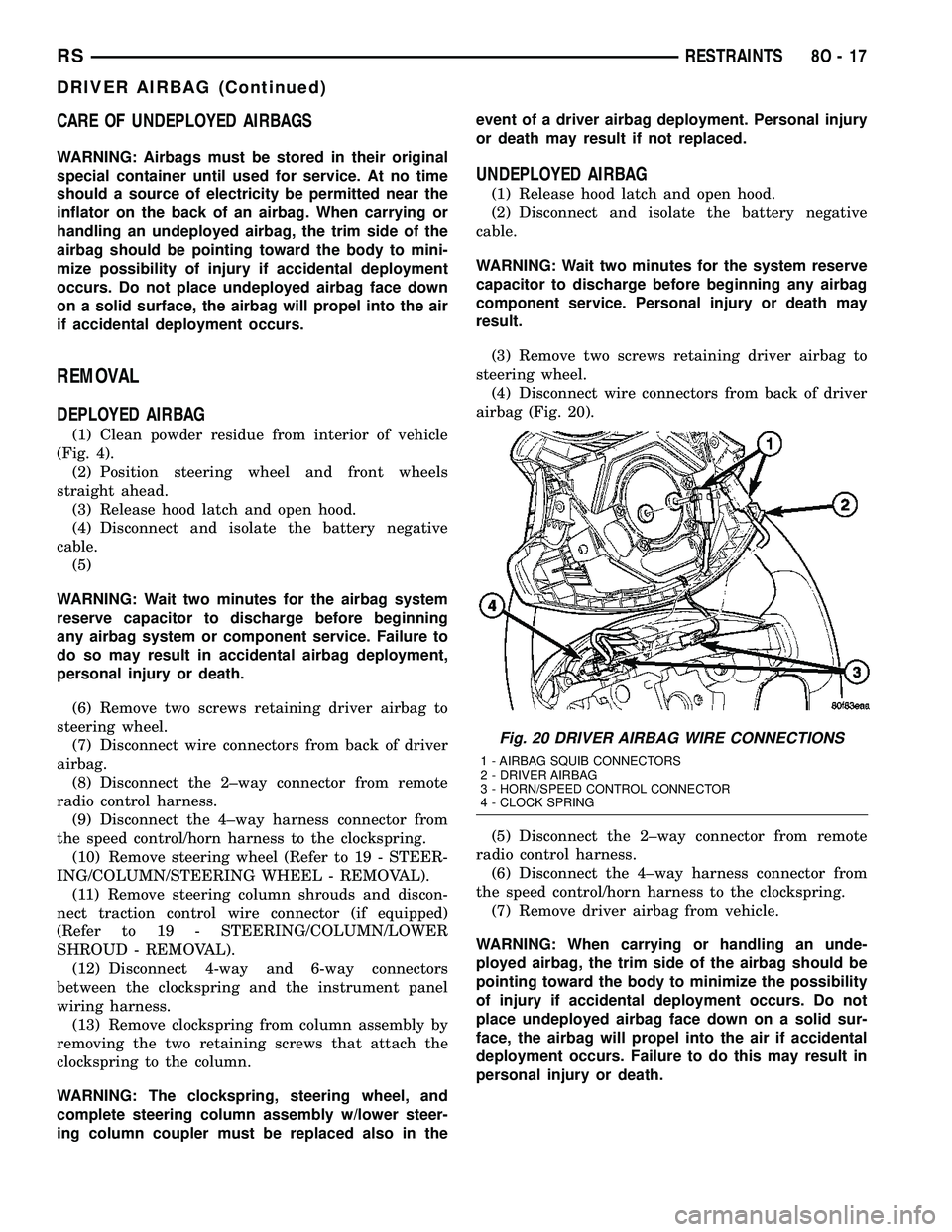
airbag (Fig. 20).
(5) Disconnect the 2±way connector from remote
radio control harness.
(6) Disconnect the 4±way harness connector from
the speed control/horn harness to the clockspring.
(7) Remove driver airbag from vehicle.
WARNING: When carrying or handling an unde-
ployed airbag, the trim side of the airbag should be
pointing toward the body to minimize the possibility
of injury if accidental deployment occurs. Do not
place undeployed airbag face down on a solid sur-
face, the airbag will propel into the air if accidental
deployment occurs. Failure to do this may result in
personal injury or death.
Fig. 20 DRIVER AIRBAG WIRE CONNECTIONS
1 - AIRBAG SQUIB CONNECTORS
2 - DRIVER AIRBAG
3 - HORN/SPEED CONTROL CONNECTOR
4 - CLOCK SPRING
RSRESTRAINTS8O-17
DRIVER AIRBAG (Continued)
Page 505 of 2339
INSTALLATION
DEPLOYED AIRBAG
(1) Perform clean up procedure (Refer to 8 - ELEC-
TRICAL/RESTRAINTS - STANDARD PROCEDURE
- SERVICE AFTER AN AIRBAG DEPLOYMENT).
(2) Install a new steering column assembly and
lower steering column coupler (Refer to 19 - STEER-
ING/COLUMN - INSTALLATION).
(3) Install the new clockspring.
(4) Connect the 4-way and 6-way connectors
between the clockspring and the instrument panel
wiring harness.
(5) Install the steering column shrouds and con-
nect traction control wire connector (if equipped)
(Refer to 19 - STEERING/COLUMN/LOWER
SHROUD - INSTALLATION).
(6) Install the steering wheel (Refer to 19 -
STEERING/COLUMN/STEERING WHEEL -
INSTALLATION).
(7) Connect the 4±way harness connector to the
speed control/horn harness to the clockspring.
(8) Connect the 2±way connector to the remote
radio control harness.
(9) Install the driver airbag and the two screws
retaining the airbag. Tighten screws to 10 N´m (90
in. lbs.)
WARNING: Do not connect the battery negative
cable (Refer to 8 - ELECTRICAL/RESTRAINTS -
DIAGNOSIS AND TESTING - AIRBAG SYSTEM). Per-
sonal injury or death may result if the system test
is not performed first.
UNDEPLOYED AIRBAG
(1) Connect the harness connector on the driver
airbag trim cover (horn, speed controls) to the clock-
spring.
(2) Connect the squib connectors to the driver air-
bag.
(3) Position the driver airbag into the steering
wheel.
(4) Install the two screws retaining the airbag.
Tighten screws to 10 N´m (90 in. lbs.)
WARNING: Do not connect the battery negative
cable (Refer to 8 - ELECTRICAL/RESTRAINTS -
DIAGNOSIS AND TESTING - AIRBAG SYSTEM). Per-
sonal injury or death may result if the system test
is not performed first.
IMPACT SENSOR
DESCRIPTION
FRONT IMPACT SENSORS
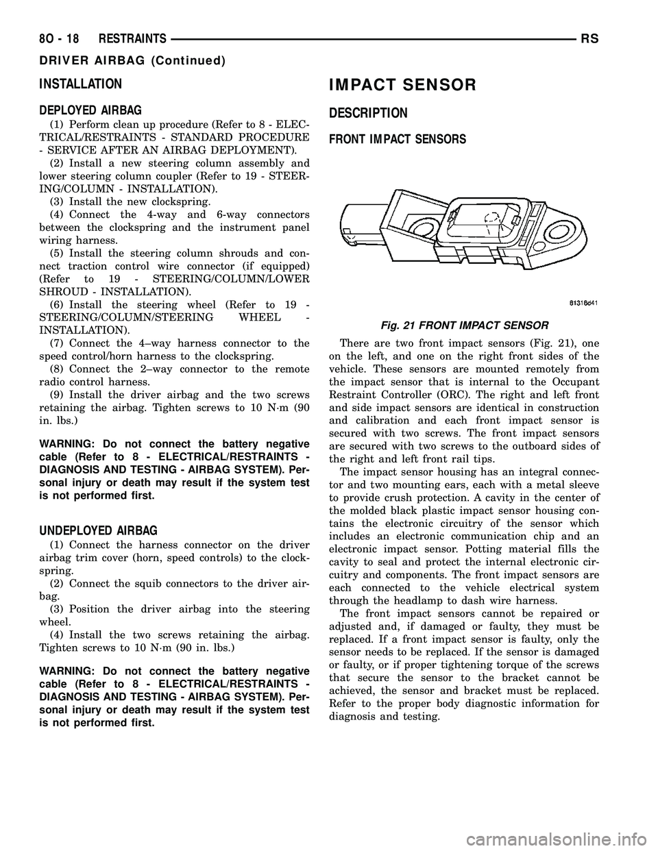
There are two front impact sensors (Fig. 21), one
on the left, and one on the right front sides of the
vehicle. These sensors are mounted remotely from
the impact sensor that is internal to the Occupant
Restraint Controller (ORC). The right and left front
and side impact sensors are identical in construction
and calibration and each front impact sensor is
secured with two screws. The front impact sensors
are secured with two screws to the outboard sides of
the right and left front rail tips.
The impact sensor housing has an integral connec-
tor and two mounting ears, each with a metal sleeve
to provide crush protection. A cavity in the center of
the molded black plastic impact sensor housing con-
tains the electronic circuitry of the sensor which
includes an electronic communication chip and an
electronic impact sensor. Potting material fills the
cavity to seal and protect the internal electronic cir-
cuitry and components. The front impact sensors are
each connected to the vehicle electrical system
through the headlamp to dash wire harness.
The front impact sensors cannot be repaired or
adjusted and, if damaged or faulty, they must be
replaced. If a front impact sensor is faulty, only the
sensor needs to be replaced. If the sensor is damaged
or faulty, or if proper tightening torque of the screws
that secure the sensor to the bracket cannot be
achieved, the sensor and bracket must be replaced.
Refer to the proper body diagnostic information for
diagnosis and testing.
Fig. 21 FRONT IMPACT SENSOR
8O - 18 RESTRAINTSRS
DRIVER AIRBAG (Continued)
Page 506 of 2339
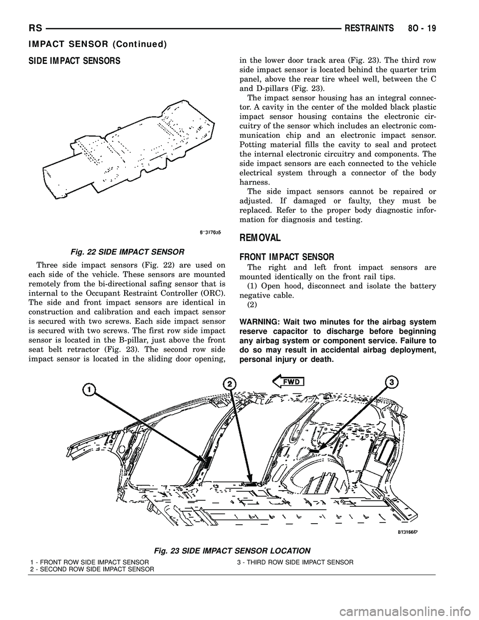
SIDE IMPACT SENSORS
Three side impact sensors (Fig. 22) are used on
each side of the vehicle. These sensors are mounted
remotely from the bi-directional safing sensor that is
internal to the Occupant Restraint Controller (ORC).
The side and front impact sensors are identical in
construction and calibration and each impact sensor
is secured with two screws. Each side impact sensor
is secured with two screws. The first row side impact
sensor is located in the B-pillar, just above the front
seat belt retractor (Fig. 23). The second row side
impact sensor is located in the sliding door opening,in the lower door track area (Fig. 23). The third row
side impact sensor is located behind the quarter trim
panel, above the rear tire wheel well, between the C
and D-pillars (Fig. 23).
The impact sensor housing has an integral connec-
tor. A cavity in the center of the molded black plastic
impact sensor housing contains the electronic cir-
cuitry of the sensor which includes an electronic com-
munication chip and an electronic impact sensor.
Potting material fills the cavity to seal and protect
the internal electronic circuitry and components. The
side impact sensors are each connected to the vehicle
electrical system through a connector of the body
harness.
The side impact sensors cannot be repaired or
adjusted. If damaged or faulty, they must be
replaced. Refer to the proper body diagnostic infor-
mation for diagnosis and testing.
REMOVAL
FRONT IMPACT SENSOR
The right and left front impact sensors are
mounted identically on the front rail tips.
(1) Open hood, disconnect and isolate the battery
negative cable.
(2)
WARNING: Wait two minutes for the airbag system
reserve capacitor to discharge before beginning
any airbag system or component service. Failure to
do so may result in accidental airbag deployment,
personal injury or death.
Fig. 23 SIDE IMPACT SENSOR LOCATION
1 - FRONT ROW SIDE IMPACT SENSOR 3 - THIRD ROW SIDE IMPACT SENSOR
2 - SECOND ROW SIDE IMPACT SENSOR
Fig. 22 SIDE IMPACT SENSOR
RSRESTRAINTS8O-19
IMPACT SENSOR (Continued)
Page 516 of 2339
restraint system protection in case there is a loss of
battery current supply to the ORC during an impact.
Two sensors are contained within the ORC, an
electronic impact sensor and a safing sensor. The
ORC also monitors inputs from eight remote impact
sensors. Two front impact sensors are located on each
outboard side of the lower radiator support, and
three side impact sensors are located on each side of
the vehicle at the B-pillar, in the lower sliding door
opening in front of the C-pillar, and over the rear
wheel well between the C and D-pillars. The elec-
tronic impact sensors are accelerometers that sense
the rate of vehicle deceleration, which provides veri-
fication of the direction and severity of an impact.
The safing sensor is an electronic accelerometer
sensor within the ORC that provides an additional
logic input to the ORC microprocessor. The safing
sensor is used to verify the need for a supplemental
restraint deployment by detecting impact energy of a
lesser magnitude than that of the primary electronic
impact sensors, and must exceed a safing threshold
in order for the airbags to deploy. Vehicles equipped
with curtain airbags, there is a second safing sensor
within the ORC to provide confirmation to the ORC
microprocessor of side impact forces. This second saf-
ing sensor is a bi-directional unit that detects impact
forces from either side of the vehicle.
Pre-programmed decision algorithms in the ORC
microprocessor determine when the deceleration rate
as signaled by the impact sensors and the safing sen-
sors indicate an impact that is severe enough to
require supplemental restraint system protection
and, based upon the severity of the monitored
impact, determines the level of front airbag deploy-
ment force required for each front seating position.
When the programmed conditions are met, the ORC
sends the proper electrical signals to deploy the dual
multistage front airbags at the programmed force
levels, the front seat belt tensioners and, if the vehi-
cle is so equipped, either curtain airbag. For vehicles
equipped with the OCS, the passenger front airbag
and seat belt tensioner will be deployed by the ORC
only if enabled by the OCM messages (PAD indicator
OFF) at the time of the impact.
To diagnose and test the ORC and all airbag sys-
tem components, use a scan tool and the appropriate
diagnostic information.
REMOVAL
WARNING: Never replace both the Occupant
Restraint Controller (ORC) and the Occupant Clas-
sification Module (OCM) at the same time. If both
require replacement, replace one, then perform the
Airbag System test (Refer to 8 - ELECTRICAL/RE-
STRAINTS - DIAGNOSIS AND TESTING - AIRBAGSYSTEM) before replacing the other. Both the ORC
and the OCM store Occupant Classification System
(OCS) calibration data, which they transfer to one
another when one of them is replaced. If both are
replaced at the same time, an irreversible fault will
be set in both modules and the OCS may malfunc-
tion and result in personal injury or death.
(1) Disconnect and isolate the battery negative
cable.
(2)
WARNING: Wait two minutes for the airbag system
reserve capacitor to discharge before beginning
any airbag system or component service. Failure to
do so may result in accidental airbag deployment,
personal injury or death.
(3) Remove storage bin from instrument panel
(Refer to 23 - BODY/INSTRUMENT PANEL/STOR-
AGE BIN - REMOVAL).
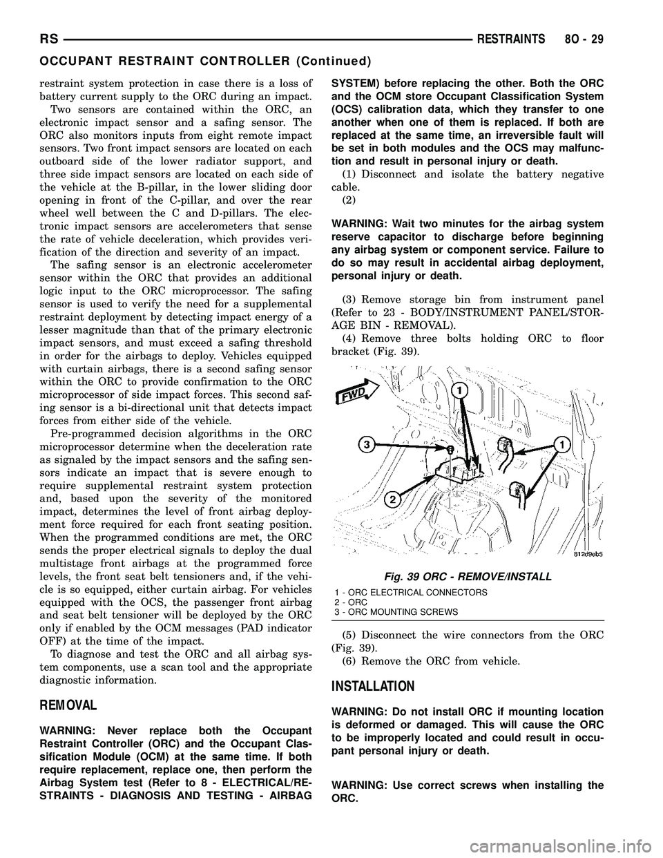
(4) Remove three bolts holding ORC to floor
bracket (Fig. 39).
(5) Disconnect the wire connectors from the ORC
(Fig. 39).
(6) Remove the ORC from vehicle.
INSTALLATION
WARNING: Do not install ORC if mounting location
is deformed or damaged. This will cause the ORC
to be improperly located and could result in occu-
pant personal injury or death.
WARNING: Use correct screws when installing the
ORC.
Fig. 39 ORC - REMOVE/INSTALL
1 - ORC ELECTRICAL CONNECTORS
2 - ORC
3 - ORC MOUNTING SCREWS
RSRESTRAINTS8O-29
OCCUPANT RESTRAINT CONTROLLER (Continued)
Page 538 of 2339

VEHICLE THEFT SECURITY
TABLE OF CONTENTS
page page
VEHICLE THEFT SECURITY
DESCRIPTION..........................1
OPERATION............................1
DIAGNOSIS AND TESTING
DIAGNOSIS AND TESTING - SENTRY KEY
REMOTE ENTRY SYSTEM...............3
DIAGNOSIS AND TESTING - VEHICLE
THEFT SECURITY SYSTEM..............3
HOOD AJAR SWITCH - EXPORT
REMOVAL.............................3
INSTALLATION..........................3
SENTRY KEY REMOTE ENTRY MODULE
DESCRIPTION..........................3OPERATION............................4
DIAGNOSIS AND TESTING - SENTRY KEY
REMOTE ENTRY MODULE...............5
REMOVAL.............................6
INSTALLATION..........................6
TRANSPONDER KEY
DESCRIPTION..........................6
OPERATION............................6
STANDARD PROCEDURE - TRANSPONDER
PROGRAMMING.......................6
VTSS/SKIS INDICATOR LAMP
DESCRIPTION..........................8
OPERATION............................8
VEHICLE THEFT SECURITY
DESCRIPTION
VEHICLE THEFT SECURITY SYSTEM
The Vehicle Theft Security System (VTSS) is
designed to protect against whole vehicle theft. The
system monitors vehicle doors, and ignition action for
unauthorized operation (hood and liftgate for RG -
Export). The alarm activates:
²Sounding of the horn
²Flashing of the headlamps/park/tail lamps
²Flashing of the headlamps
²An engine kill feature (with SKREES)
SENTRY KEY REMOTE ENTRY SYSTEM
The Sentry Key Remote Entry System (SKREES)
is available as a factory-installed option on this vehi-
cle. It is designed to provide passive protection
against unauthorized vehicle use by disabling the
engine, after two (2) seconds of running, whenever an
invalid key is used to start the vehicle. The SKIS is
active whenever the ignition is on and does not
require any customer intervention. The primary com-
ponents of the system are the Sentry Key Remote
Entry Module (SKREEM), Sentry Key (integrated
key with tranponder and RKE on a circuit board),
indicator light, Body Control Module (BCM), and the
Powertrain Control Module (PCM). The SKREEM is
mounted to the steering column with the molded,
integral antenna mounted on the ignition housing.
The indicator light, is located in the Mechanical
Instrument Cluster (MIC).
OPERATION
VEHICLE THEFT SECURITY SYSTEM
Upon failure of proper Sentry Key Remote Entry
Module (SKREEM) communication to the PCM, the
PCM will shut off fuel after two seconds of run time.
The engine will not re-crank on the key cycle that
the failure occurred, a full key down sequence must
be performed for the engine to crank again. After six
consecutive fuel shut-offs, the engine will no longer
crank on subsequent key cycles. The failure must be
corrected and a valid communication process between
the SKREEM and the PCM must occur for the
engine to crank and start again.
The electronics for the VTSS are part of the Body
Control Module (BCM). The system is armed when
the vehicle is locked using the:
²Power door lock switches (with any door ajar)
²Remote Keyless Entry integrated key.
²Door Cylinder Lock Switches (RG only).
For vehicles equipped with Sentry Key Remote
Entry System (SKREES), the doors do not have to be
locked to enable the fuel shut off feature.
After the vehicle is locked and the last door is
closed, the set LED indicator in the Mechanical
Instrument Cluster (MIC) will flash quickly for 16
seconds, indicating that arming is in progress. If no
monitored systems are activated during this period,
the system will arm. The LED will extinguish unless
the liftgate is open. If the liftgate is open, the LED
will flash at a slower rate. This indicates that the
system is armed.
RSVEHICLE THEFT SECURITY8Q-1