diagram CHRYSLER CARAVAN 2005 Repair Manual
[x] Cancel search | Manufacturer: CHRYSLER, Model Year: 2005, Model line: CARAVAN, Model: CHRYSLER CARAVAN 2005Pages: 2339, PDF Size: 59.69 MB
Page 2169 of 2339
A/C COMPRESSOR CLUTCH
RELAY
DESCRIPTION
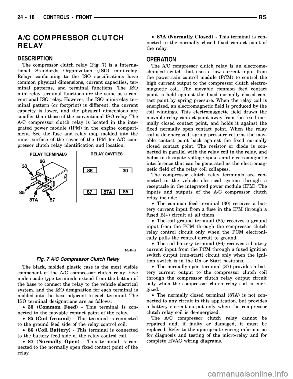
The compressor clutch relay (Fig. 7) is a Interna-
tional Standards Organization (ISO) mini-relay.
Relays conforming to the ISO specifications have
common physical dimensions, current capacities, ter-
minal patterns, and terminal functions. The ISO
mini-relay terminal functions are the same as a con-
ventional ISO relay. However, the ISO mini-relay ter-
minal pattern (or footprint) is different, the current
capacity is lower, and the physical dimensions are
smaller than those of the conventional ISO relay. The
A/C compressor clutch relay is located in the inte-
grated power module (IPM) in the engine compart-
ment. See the fuse and relay map molded into the
inner surface of the cover of the IPM for A/C com-
pressor clutch relay identification and location.
The black, molded plastic case is the most visible
component of the A/C compressor clutch relay. Five
male spade-type terminals extend from the bottom of
the base to connect the relay to the vehicle electrical
system, and the ISO designation for each terminal is
molded into the base adjacent to each terminal. The
ISO terminal designations are as follows:
²30 (Common Feed)- This terminal is con-
nected to the movable contact point of the relay.
²85 (Coil Ground)- This terminal is connected
to the ground feed side of the relay control coil.
²86 (Coil Battery)- This terminal is connected
to the battery feed side of the relay control coil.
²87 (Normally Open)- This terminal is con-
nected to the normally open fixed contact point of the
relay.²87A (Normally Closed)- This terminal is con-
nected to the normally closed fixed contact point of
the relay.
OPERATION
The A/C compressor clutch relay is an electrome-
chanical switch that uses a low current input from
the powertrain control module (PCM) to control the
high current output to the compressor clutch electro-
magnetic coil. The movable common feed contact
point is held against the fixed normally closed con-
tact point by spring pressure. When the relay coil is
energized, an electromagnetic field is produced by the
coil windings. This electromagnetic field draws the
movable relay contact point away from the fixed nor-
mally closed contact point, and holds it against the
fixed normally open contact point. When the relay
coil is de-energized, spring pressure returns the mov-
able contact point back against the fixed normally
closed contact point. The resistor or diode is con-
nected in parallel with the relay coil in the relay, and
helps to dissipate voltage spikes and electromagnetic
interference that can be generated as the electromag-
netic field of the relay coil collapses.
The compressor clutch relay terminals are con-
nected to the vehicle electrical system through a
receptacle in the integrated power module (IPM). The
inputs and outputs of the A/C compressor clutch
relay include:
²The common feed terminal (30) receives a bat-
tery current input from a fuse in the IPM through a
fused B(+) circuit at all times.
²The coil ground terminal (85) receives a ground
input from the PCM through the compressor clutch
relay control circuit only when the PCM electroni-
cally pulls the control circuit to ground.
²The coil battery terminal (86) receives a battery
current input from the PCM through a fused ignition
switch output (run-start) circuit only when the igni-
tion switch is in the On or Start positions.
²The normally open terminal (87) provides a bat-
tery current output to the compressor clutch coil
through the compressor clutch relay output circuit
only when the compressor clutch relay coil is ener-
gized.
²The normally closed terminal (87A) is not con-
nected to any circuit in this application, but provides
a battery current output only when the compressor
clutch relay coil is de-energized.
The A/C compressor clutch relay cannot be
repaired and, if faulty or damaged, it must be
replaced. Refer to the appropriate wiring information
for diagnosis and testing of the micro-relay and for
complete HVAC wiring diagrams.
Fig. 7 A/C Compressor Clutch Relay
24 - 18 CONTROLS - FRONTRS
Page 2175 of 2339
The blower motor relay terminals are connected to
the vehicle electrical system through a receptacle in
the Integrated Power Module (IPM). The inputs and
outputs of the blower motor relay include:
²The common feed terminal (30) receives a bat-
tery current input from the battery through a B(+)
circuit at all times.
²The coil ground terminal (85) receives a ground
input through the front/rear blower motor relay con-
trol circuit only when the FCM electronically pulls
the control circuit to ground.
²The coil battery terminal (86) receives a battery
current input from the battery through a B(+) circuit
at all times.
²The normally open terminal (87) provides a bat-
tery current output to the blower motor resistor
(manual heater-A/C control) or blower power module
(automatic heater-A/C control) through a fuse in the
IPM on the fused front blower motor relay output cir-
cuit only when the blower motor relay coil is ener-
gized.
²The normally closed terminal (87A) is not con-
nected to any circuit in this application, but provides
a battery current output only when the blower motor
relay coil is de-energized.
Refer to the appropriate wiring information for
diagnosis and testing of the micro-relay and for com-
plete HVAC wiring diagrams.
REMOVAL
(1) Disconnect and isolate the negative battery
cable.
(2) Remove the cover from the integrated power
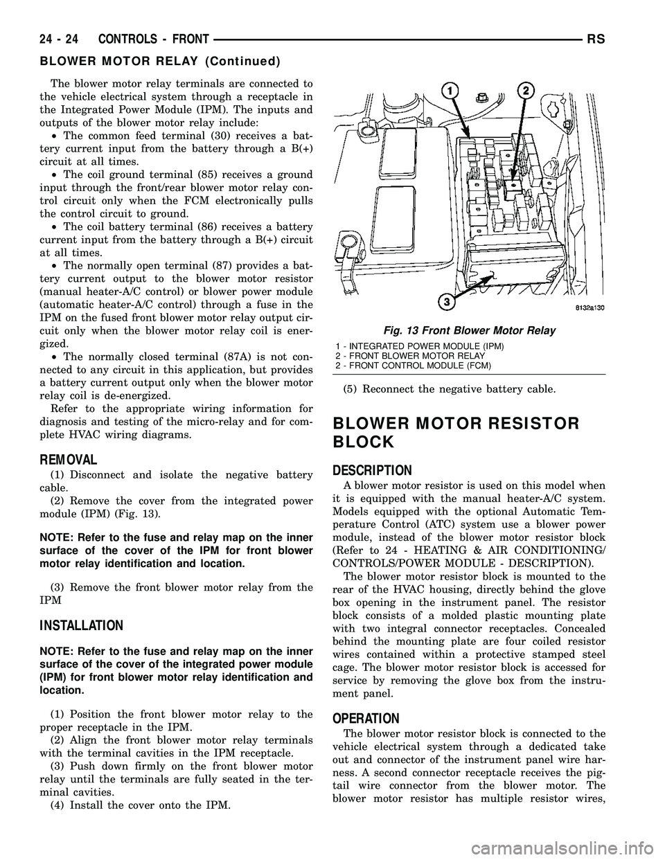
module (IPM) (Fig. 13).
NOTE: Refer to the fuse and relay map on the inner
surface of the cover of the IPM for front blower
motor relay identification and location.
(3) Remove the front blower motor relay from the
IPM
INSTALLATION
NOTE: Refer to the fuse and relay map on the inner
surface of the cover of the integrated power module
(IPM) for front blower motor relay identification and
location.
(1) Position the front blower motor relay to the
proper receptacle in the IPM.
(2) Align the front blower motor relay terminals
with the terminal cavities in the IPM receptacle.
(3) Push down firmly on the front blower motor
relay until the terminals are fully seated in the ter-
minal cavities.
(4) Install the cover onto the IPM.(5) Reconnect the negative battery cable.
BLOWER MOTOR RESISTOR
BLOCK
DESCRIPTION
A blower motor resistor is used on this model when
it is equipped with the manual heater-A/C system.
Models equipped with the optional Automatic Tem-
perature Control (ATC) system use a blower power
module, instead of the blower motor resistor block
(Refer to 24 - HEATING & AIR CONDITIONING/
CONTROLS/POWER MODULE - DESCRIPTION).
The blower motor resistor block is mounted to the
rear of the HVAC housing, directly behind the glove
box opening in the instrument panel. The resistor
block consists of a molded plastic mounting plate
with two integral connector receptacles. Concealed
behind the mounting plate are four coiled resistor
wires contained within a protective stamped steel
cage. The blower motor resistor block is accessed for
service by removing the glove box from the instru-
ment panel.
OPERATION
The blower motor resistor block is connected to the
vehicle electrical system through a dedicated take
out and connector of the instrument panel wire har-
ness. A second connector receptacle receives the pig-
tail wire connector from the blower motor. The
blower motor resistor has multiple resistor wires,
Fig. 13 Front Blower Motor Relay
1 - INTEGRATED POWER MODULE (IPM)
2 - FRONT BLOWER MOTOR RELAY
2 - FRONT CONTROL MODULE (FCM)
24 - 24 CONTROLS - FRONTRS
BLOWER MOTOR RELAY (Continued)
Page 2176 of 2339
each of which will reduce the current flow through
the blower motor to change the blower motor speed.
The blower motor switch in the manual heater-A/C
system directs the ground path for the blower motor
through the correct resistor wire to obtain the
selected speed.
With the blower motor switch in the lowest speed
position, the ground path for the motor is applied
through all of the resistor wires. Each higher speed
selected with the blower motor switch applies the
blower motor ground path through fewer of the resis-
tor wires, increasing the blower motor speed.
The blower motor resistor cannot be adjusted or
repaired and, if faulty or damaged, it must be
replaced.
DIAGNOSIS AND TESTING
FRONT BLOWER MOTOR RESISTOR BLOCK
WARNING: ON VEHICLES EQUIPPED WITH AIR-
BAGS, DISABLE THE AIRBAG SYSTEM BEFORE
ATTEMPTING ANY STEERING WHEEL, STEERING
COLUMN, OR INSTRUMENT PANEL COMPONENT
DIAGNOSIS OR SERVICE. DISCONNECT AND ISO-
LATE THE BATTERY NEGATIVE (GROUND) CABLE,
THEN WAIT TWO MINUTES FOR THE AIRBAG SYS-
TEM CAPACITOR TO DISCHARGE BEFORE PER-
FORMING FURTHER DIAGNOSIS OR SERVICE. THIS
IS THE ONLY SURE WAY TO DISABLE THE AIRBAG
SYSTEM. FAILURE TO TAKE THE PROPER PRE-
CAUTIONS COULD RESULT IN ACCIDENTAL AIR-
BAG DEPLOYMENT AND POSSIBLE PERSONAL
INJURY.
For circuit descriptions and diagrams, refer to the
appropriate wiring information. The wiring informa-
tion includes wiring diagrams, proper wire and con-
nector repair procedures, further details on wire
harness routing and retention, as well as pin-out and
location views for the various wire harness connec-
tors, splices and grounds.
(1) Disconnect and isolate the battery negative
cable.
(2) Remove the glove box from the instrument
panel (Refer to 23 - BODY/INSTRUMENT PANEL/
GLOVE BOX - REMOVAL).
(3) Disconnect the two wire harness connectors
from the blower motor resistor block.
(4) Check for continuity between each of the
blower motor switch input terminals of the resistor
and the resistor output terminal. In each case there
should be continuity. If OK, repair the wire harness
circuits between the blower motor switch and the
blower motor resistor, blower motor or blower motorrelay as required. If not OK, replace the faulty
blower motor resistor block.
REMOVAL
WARNING: ON VEHICLES EQUIPPED WITH AIR-
BAGS, DISABLE THE AIRBAG SYSTEM BEFORE
ATTEMPTING ANY STEERING WHEEL, STEERING
COLUMN, OR INSTRUMENT PANEL COMPONENT
DIAGNOSIS OR SERVICE. DISCONNECT AND ISO-
LATE THE BATTERY NEGATIVE (GROUND) CABLE,
THEN WAIT TWO MINUTES FOR THE AIRBAG SYS-
TEM CAPACITOR TO DISCHARGE BEFORE PER-
FORMING FURTHER DIAGNOSIS OR SERVICE. THIS
IS THE ONLY SURE WAY TO DISABLE THE AIRBAG
SYSTEM. FAILURE TO TAKE THE PROPER PRE-
CAUTIONS COULD RESULT IN ACCIDENTAL AIR-
BAG DEPLOYMENT AND POSSIBLE PERSONAL
INJURY.
WARNING: THE BLOWER MOTOR RESISTOR
BLOCK MAY GET VERY HOT DURING NORMAL
OPERATION. IF THE BLOWER MOTOR WAS
TURNED ON PRIOR TO SERVICING THE BLOWER
MOTOR RESISTOR BLOCK, WAIT FIVE MINUTES
TO ALLOW THE BLOWER MOTOR RESISTORS TO
COOL BEFORE PERFORMING DIAGNOSIS OR SER-
VICE. FAILURE TO TAKE THIS PRECAUTION CAN
RESULT IN PERSONAL INJURY.
CAUTION: Do not operate the blower motor with the
blower motor resistor removed from the circuit.
Failure to take this precaution can result in vehicle
damage.
(1) Disconnect and isolate the battery negative
cable.
(2) Remove the glove box from the instrument
panel (Refer to 23 - BODY/INSTRUMENT PANEL/
GLOVE BOX - REMOVAL).
(3) Disconnect the two wire harness connectors
from the blower motor resistor block (Fig. 14).
(4) Remove the two screws that secure the blower
motor resistor block to the HVAC housing.
(5) Remove the resistor block from the HVAC
housing.
INSTALLATION
(1) Position the blower motor resistor block into
the HVAC housing.
(2) Install the two screws that secure the blower
motor resistor block to the HVAC housing. Tighten
the screws to 2 N´m (17 in. lbs.).
(3) Connect the two wire connectors to the resistor
block.
RSCONTROLS - FRONT24-25
BLOWER MOTOR RESISTOR BLOCK (Continued)
Page 2188 of 2339
²The normally open terminal (87) provides a bat-
tery current output to the blower motor resistor
(manual heater-A/C control) or blower power module
(ATC heater-A/C control) through a fuse in the IPM
on the fused rear blower motor relay output circuit
only when the blower motor relay coil is energized.
²The normally closed terminal (87A) is not con-
nected to any circuit in this application, but provides
a battery current output only when the rear blower
motor relay coil is de-energized.
Refer to the appropriate wiring information for
diagnosis and testing of the micro-relay and for com-
plete HVAC wiring diagrams.
REMOVAL
(1) Disconnect and isolate the negative battery
cable.
(2) Remove the cover from the integrated power
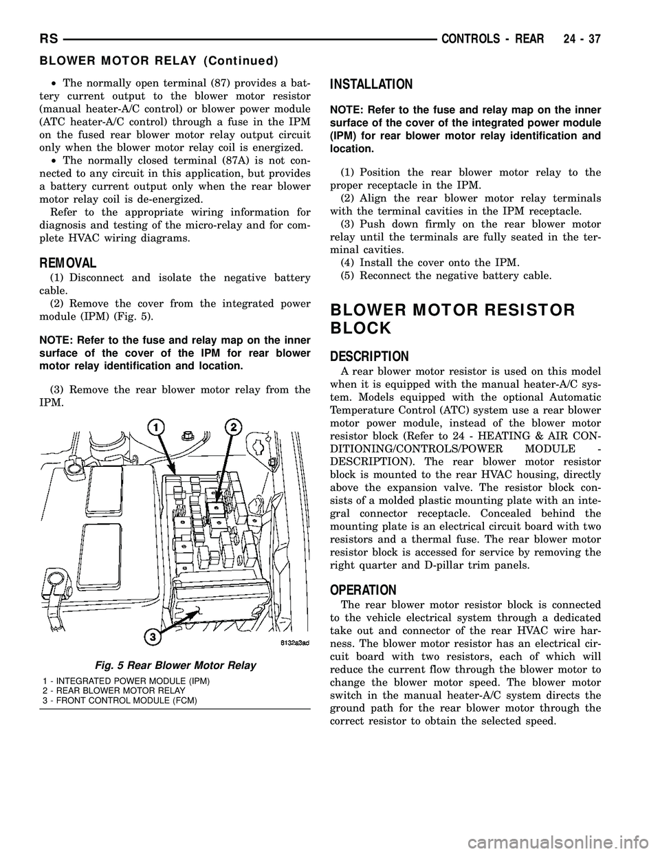
module (IPM) (Fig. 5).
NOTE: Refer to the fuse and relay map on the inner
surface of the cover of the IPM for rear blower
motor relay identification and location.
(3) Remove the rear blower motor relay from the
IPM.
INSTALLATION
NOTE: Refer to the fuse and relay map on the inner
surface of the cover of the integrated power module
(IPM) for rear blower motor relay identification and
location.
(1) Position the rear blower motor relay to the
proper receptacle in the IPM.
(2) Align the rear blower motor relay terminals
with the terminal cavities in the IPM receptacle.
(3) Push down firmly on the rear blower motor
relay until the terminals are fully seated in the ter-
minal cavities.
(4) Install the cover onto the IPM.
(5) Reconnect the negative battery cable.
BLOWER MOTOR RESISTOR
BLOCK
DESCRIPTION
A rear blower motor resistor is used on this model
when it is equipped with the manual heater-A/C sys-
tem. Models equipped with the optional Automatic
Temperature Control (ATC) system use a rear blower
motor power module, instead of the blower motor
resistor block (Refer to 24 - HEATING & AIR CON-
DITIONING/CONTROLS/POWER MODULE -
DESCRIPTION). The rear blower motor resistor
block is mounted to the rear HVAC housing, directly
above the expansion valve. The resistor block con-
sists of a molded plastic mounting plate with an inte-
gral connector receptacle. Concealed behind the
mounting plate is an electrical circuit board with two
resistors and a thermal fuse. The rear blower motor
resistor block is accessed for service by removing the
right quarter and D-pillar trim panels.
OPERATION
The rear blower motor resistor block is connected
to the vehicle electrical system through a dedicated
take out and connector of the rear HVAC wire har-
ness. The blower motor resistor has an electrical cir-
cuit board with two resistors, each of which will
reduce the current flow through the blower motor to
change the blower motor speed. The blower motor
switch in the manual heater-A/C system directs the
ground path for the rear blower motor through the
correct resistor to obtain the selected speed.
Fig. 5 Rear Blower Motor Relay
1 - INTEGRATED POWER MODULE (IPM)
2 - REAR BLOWER MOTOR RELAY
3 - FRONT CONTROL MODULE (FCM)
RSCONTROLS - REAR24-37
BLOWER MOTOR RELAY (Continued)
Page 2189 of 2339
With the blower motor switch in the lowest speed
position, the ground path for the motor is applied
through both resistors. Each higher speed selected
with the blower motor switch applies the blower
motor ground path through fewer of the resistors,
increasing the blower motor speed. When the blower
motor switch is in the highest speed position, the
blower motor resistors are bypassed and the blower
motor receives a direct path to ground through the
blower motor switch.
The rear blower motor resistor block cannot be
adjusted or repaired and, if faulty or damaged, it
must be replaced.
DIAGNOSIS AND TESTING
REAR BLOWER MOTOR RESISTOR BLOCK
For circuit descriptions and diagrams, refer to the
appropriate wiring information. The wiring informa-
tion includes wiring diagrams, proper wire and con-
nector repair procedures, further details on wire
harness routing and retention, as well as pin-out and
location views for the various wire harness connec-
tors, splices and grounds.
(1) Disconnect and isolate the battery negative
cable.
(2) Disconnect the rear HVAC wire harness con-
nector from the rear blower motor resistor.
(3) Check for continuity between each of the
blower motor switch input terminals of the blower
motor resistor and the resistor output terminal. In
each case there should be continuity. If OK, repair
the wire harness circuits between the blower motor
switch and the blower motor resistor, blower motor or
blower motor relay as required. If not OK, replace
the faulty blower motor resistor block.
REMOVAL
WARNING: THE REAR BLOWER MOTOR RESISTOR
BLOCK MAY GET VERY HOT DURING NORMAL
OPERATION. IF THE BLOWER MOTOR WAS
TURNED ON PRIOR TO SERVICING THE BLOWER
MOTOR RESISTOR BLOCK, WAIT FIVE MINUTES
TO ALLOW THE BLOWER MOTOR RESISTORS TO
COOL BEFORE PERFORMING DIAGNOSIS OR SER-
VICE. FAILURE TO TAKE THIS PRECAUTION CAN
RESULT IN PERSONAL INJURY.CAUTION: Do not operate the blower motor with the
blower motor resistor block removed from the cir-
cuit. Failure to take this precaution can result in
vehicle damage.
(1) Disconnect and isolate the battery negative
cable.
(2) Remove the right quarter trim panel and right
D-pillar trim panel from the quarter inner panel
(Refer to 23 - BODY/INTERIOR/QUARTER TRIM
PANEL - REMOVAL).
(3) Disconnect the rear HVAC wire harness con-
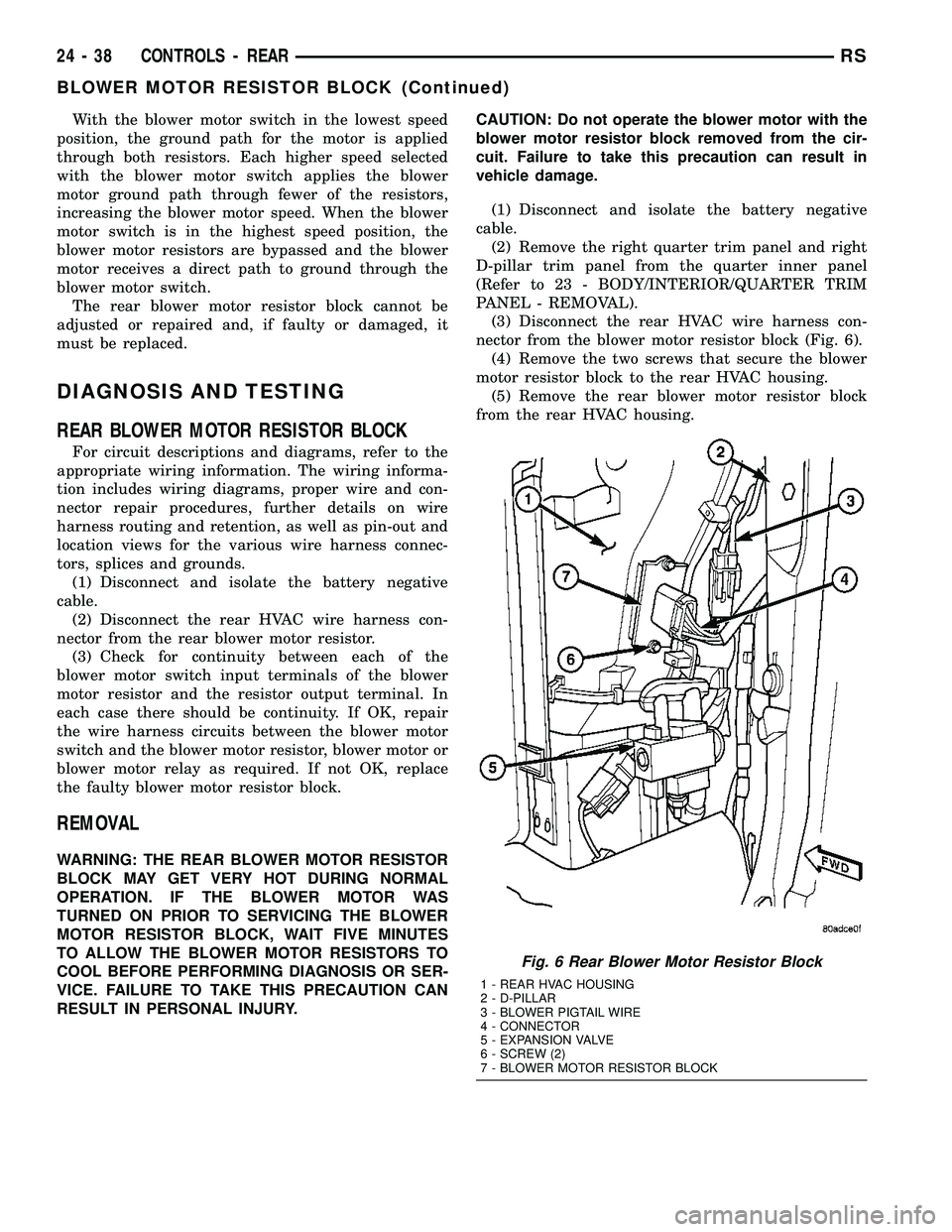
nector from the blower motor resistor block (Fig. 6).
(4) Remove the two screws that secure the blower
motor resistor block to the rear HVAC housing.
(5) Remove the rear blower motor resistor block
from the rear HVAC housing.
Fig. 6 Rear Blower Motor Resistor Block
1 - REAR HVAC HOUSING
2 - D-PILLAR
3 - BLOWER PIGTAIL WIRE
4 - CONNECTOR
5 - EXPANSION VALVE
6 - SCREW (2)
7 - BLOWER MOTOR RESISTOR BLOCK
24 - 38 CONTROLS - REARRS
BLOWER MOTOR RESISTOR BLOCK (Continued)
Page 2197 of 2339
whenever the ignition switch is in the On position
and the A/C-heater control power is turned on.
The blower motor receives battery current when-
ever the front blower motor relay is energized. The
front blower motor relay output circuit is protected
by a fuse in the Integrated Power Module (IPM)
located in the engine compartment near the battery.
In the manual heater-A/C system, the blower motor
speed is controlled by regulating the path to ground
through the blower control switch and the blower
motor resistor. In the ATC system, the blower motor
speed is controlled by an electronic blower motor
power module, which uses a pulse width modulated
input from the ATC module and feedback from the
blower motor to regulate the blower motor ground
path it provides. The blower motor and wheel are
used to control the velocity of air moving through the
HVAC housing by spinning the blower wheel within
the housing at the selected speed or, in the ATC sys-
tem, at the selected or programmed speed.
DIAGNOSIS AND TESTING
FRONT BLOWER MOTOR
BLOWER MOTOR INOPERATIVE
WARNING: ON VEHICLES EQUIPPED WITH AIR-
BAGS, DISABLE THE AIRBAG SYSTEM BEFORE
ATTEMPTING ANY STEERING WHEEL, STEERING
COLUMN, OR INSTRUMENT PANEL COMPONENT
DIAGNOSIS OR SERVICE. DISCONNECT AND ISO-
LATE THE BATTERY NEGATIVE (GROUND) CABLE,
THEN WAIT TWO MINUTES FOR THE AIRBAG SYS-
TEM CAPACITOR TO DISCHARGE BEFORE PER-
FORMING FURTHER DIAGNOSIS OR SERVICE. THIS
IS THE ONLY SURE WAY TO DISABLE THE AIRBAG
SYSTEM. FAILURE TO TAKE THE PROPER PRE-
CAUTIONS COULD RESULT IN ACCIDENTAL AIR-
BAG DEPLOYMENT AND POSSIBLE PERSONAL
INJURY.
For circuit descriptions and diagrams, refer to the
appropriate wiring information. The wiring informa-
tion includes wiring, diagrams, proper wire and con-
nector repair procedures, further details on wire
harness routing and retention, as well as pin-out and
location views for the various wire harness connec-
tors, splices and grounds.BLOWER MOTOR ELECTRICAL DIAGNOSIS
(1) Check the fuse (Fuse 10 - 40 ampere) in the
Integrated Power Module (IPM). If OK, go to Step 2.
If not OK, repair the shorted circuit or component as
required and replace the faulty fuse.
(2) Turn the ignition switch to the On position. Be
certain that the A/C-heater control power is turned
on. Check for battery voltage at the fuse (Fuse 10 -
40 ampere) in the IPM. If OK, go to Step 3. If not
OK, check the front blower motor relay.
(3) Turn the ignition switch to the Off position.
Disconnect and isolate the battery negative cable.
Disconnect the front HVAC wire harness connector
for the front blower motor resistor block (Manual
Temperature Control) or the front blower motor
power module (Automatic Temperature Control) from
the resistor or module connector receptacle. Recon-
nect the battery negative cable. Turn the ignition
switch to the On position. Be certain that the A/C-
heater control power is turned on. Check for battery
voltage at the fused front blower motor relay output
circuit cavity of the front HVAC wire harness connec-
tor for the front blower motor resistor block (MTC) or
the front blower motor power module (ATC). If OK,
go to Step 4. If not OK, repair the open fused front
blower motor relay output circuit to the IPM as
required.
(4) Turn the ignition switch to the Off position.
Disconnect and isolate the battery negative cable.
Disconnect the front blower motor pigtail wire con-
nector from the connector receptacle of the front
blower motor resistor block (MTC) or the front
blower motor power module (ATC). Use jumper wires
to connect a battery and ground feeds to the blower
motor pigtail wire connector. The blower motor
should operate. If OK with MTC, proceed to diagno-
sis of the front blower motor resistor block (Refer to
24 - HEATING & AIR CONDITIONING/CONTROLS
- FRONT/BLOWER MOTOR RESISTOR - DIAGNO-
SIS AND TESTING). If OK with ATC, use a DRBIII
scan tool to diagnose the front blower motor power
module. Refer to Body Diagnostic information. If not
OK with MTC or ATC, replace the faulty front blower
motor.
BLOWER MOTOR NOISE OR VIBRATION
Refer to the Blower Motor Noise/Vibration Diagno-
sis chart for basic checks of the blower motor when a
vibration or noise is present (Fig. 7).
24 - 46 DISTRIBUTION - FRONTRS
BLOWER MOTOR (Continued)
Page 2209 of 2339
DIAGNOSIS AND TESTING
REAR BLOWER MOTOR
BLOWER MOTOR INOPERATIVE
For circuit descriptions and diagrams, refer to the
appropriate wiring information. The wiring informa-
tion includes wiring, diagrams, proper wire and con-
nector repair procedures, further details on wire
harness routing and retention, as well as pin-out and
location views for the various wire harness connec-
tors, splices and grounds.
BLOWER MOTOR ELECTRICAL DIAGNOSIS
(1) Check the fuse (Fuse 12 - 25 ampere) in the
Integrated Power Module (IPM). If OK, go to Step 2.
If not OK, repair the shorted circuit or component as
required and replace the faulty fuse.
(2) Turn the ignition switch to the On position. Be
certain that the rear A/C-heater control power is
turned on. Check for battery voltage at the fuse
(Fuse 12 - 25 ampere) in the IPM. If OK, go to Step
3. If not OK, check the rear blower motor relay.
(3) Turn the ignition switch to the Off position.
Disconnect and isolate the battery negative cable.
Disconnect the rear HVAC wire harness connector
from the rear blower motor resistor block (Manual
Temperature Control) or the rear blower motor power
module (Automatic Temperature Control). Reconnect
the battery negative cable. Turn the ignition switch
to the On position. Be certain that the rear A/C-
heater control power is turned on. Check for battery
voltage at the fused rear blower motor relay output
circuit cavity of the rear HVAC wire harness connec-
tor for the rear blower motor resistor block (MTC) or
the rear blower motor power module (ATC). If OK, go
to Step 4. If not OK, repair the open fused front
blower motor relay output circuit to the IPM as
required.
(4) Turn the ignition switch to the Off position.
Disconnect and isolate the battery negative cable.Disconnect the rear blower motor pigtail wire connec-
tor from the rear HVAC wire harness (MTC) or the
rear blower power module (ATC). Use jumper wires
to connect a battery and ground feeds to the blower
motor pigtail wire connector. The rear blower motor
should operate. If OK with MTC, proceed to diagno-
sis of the rear blower motor resistor block (Refer to
24 - HEATING & AIR CONDITIONING/CONTROLS
- REAR/BLOWER MOTOR RESISTOR - DIAGNOSIS
AND TESTING). If OK with ATC, use a DRBIII scan
tool to diagnose the rear blower motor power module.
Refer to the appropriate diagnostic information. If
not OK with MTC or ATC, replace the faulty rear
blower motor.
BLOWER MOTOR NOISE OR VIBRATION
Refer to the Blower Motor Noise/Vibration Diagno-
sis chart for basic checks of the blower motor when a
vibration or noise is present (Fig. 3).
REMOVAL
WARNING: REFER TO THE APPLICABLE WARN-
INGS AND CAUTIONS FOR THIS SYSTEM BEFORE
PERFORMING THE FOLLOWING OPERATION (Refer
to 24 - HEATING & AIR CONDITIONING/PLUMBING -
WARNING) and (Refer to 24 - HEATING & AIR CON-
DITIONING/PLUMBING - CAUTION).
(1) Remove the rear HVAC housing from the vehi-
cle (Refer to 24 - HEATING & AIR CONDITIONING/
DISTRIBUTION/HVAC HOUSING - REMOVAL).
(2) Disconnect the rear blower motor pigtail wire
connector.
NOTE: With the Manual Temperature Control sys-
tem, the blower motor pigtail wire is connected to a
take out and connector of the rear HVAC wire har-
ness. With the Automatic Temperature Control sys-
tem , the blower pigtail wire is connected to a
receptacle on the blower motor power module.
24 - 58 DISTRIBUTION - REARRS
BLOWER MOTOR (Continued)
Page 2311 of 2339
DEFOGGER RELAY - DESCRIPTION,REAR WINDOW ....................... 8G-3
DEFOGGER RELAY - INSTALLATION, REAR WINDOW ....................... 8G-4
DEFOGGER RELAY - OPERATION, REAR WINDOW ............................ 8G-3
DEFOGGER RELAY - REMOVAL, REAR WINDOW ............................ 8G-4
DEFOGGER SWITCH - DESCRIPTION, REAR WINDOW ....................... 8G-4
DEFOGGER SWITCH - OPERATION, REAR WINDOW ............................ 8G-4
DEFROSTER DUCT - INSTALLATION ......24-50
DEFROSTER DUCT - REMOVAL ..........24-49
DEMAGNETIZING, STANDARD PROCEDURE - COMPASS ...............8M-5
DEMISTER DUCTS - INSTALLATION, INSTRUMENT PANEL .................. 24-54
DEMISTER DUCTS - REMOVAL, INSTRUMENT PANEL .................. 24-54
DEMISTER OUTLETS, INSTALLATION - FRONT ............................. 24-45
DEMISTER OUTLETS, REMOVAL - FRONT . 24-44
DEPLOYMENT - STANDARD PROCEDURE, SERVICE AFTER AN
AIRBAG ............................. 8O-7
DETECTION ASSY - INSTALLATION, NATURAL VAC LEAK .................. 25-14
DETECTION ASSY - REMOVAL, NATURAL VAC LEAK .......................... 25-14
DETECTION PUMP - INSTALLATION, LEAK .............................. 25-15
DETECTION PUMP - REMOVAL, LEAK ......25-15
DEVICES - STANDARD PROCEDURE, ELECTROSTATIC DISCHARGE (ESD)
SENSITIVE ........................8W -01-8
DIAGNOSTIC SYSTEM, DIAGNOSIS AND TESTING - ON-BOARD .................8F-22
DIAGNOSTIC TROUBLE CODES - STANDARD PROCEDURE, OBTAINING .....8E-15
DIAGRAMS - 4XTE TRANSAXLE HYDRAULIC SCHEMATICS,
SCHEMATICS .................. 21-199,21-54
DIAGRAMS - DESCRIPTION, HOW TO USE WIRING ......................8W -01-1
DIAGRAMS - SPECIAL TOOLS, SCHEMATICS ........................ 21-68
DIESEL - DESCRIPTION ...............19-52
DIESEL - INSTALLATION ...............19-53
DIESEL - REMOVAL ................... 19-52
DIESEL ENGINE - DESCRIPTION, FUEL REQUIREMENTS .......................0-6
DIESEL ENGINES - DESCRIPTION, ENGINE OIL ...........................0-6
DIESEL ENGINES - EXPORT - DESCRIPTION ........................ 0-21
DIESEL ENGINES, INSTALLATION - 2.5L/2.8L ........................... 24-78
DIESEL ENGINES, REMOVAL - 2.5L/2.8L . . 24-77
DIFFERENTIAL BEARING PRELOAD - ADJUSTMENT ...................... 21-228
DIFFERENTIAL BEARING PRELOAD MEASUREMENT AND ADJUSTMENT,
ADJUSTMENTS ...................... 21-79
DIMENSIONS - FOLD-IN-FLOOR SEATS ONLY - SPECIFICATIONS, FRAME ........13-11
DIMENSIONS - SPECIFICATIONS, BODY OPENING .......................... 23-180
DIMENSIONS - SPECIFICATIONS, FRAME . . . 13-6
DIODE - INSTALLATION ............8W-01-14
DIODE - REMOVAL ................8W -01-14
DISABLED INDICATOR - DESCRIPTION, PASSENGER AIRBAG .................8O-33
DISABLED INDICATOR - INSTALLATION, PASSENGER AIRBAG .................8O-34
DISABLED INDICATOR - OPERATION, PASSENGER AIRBAG .................8O-33
DISABLED INDICATOR - REMOVAL, PASSENGER AIRBAG .................8O-34
DISASSEMBLY/ASSEMBLY - STANDARD PROCEDURE, TRANSMISSION COOLER
LINE QUICK CONNECT FITTING ...........7-38
DISC BRAKE CALIPER - INSTALLATION, REAR ............................... 5-30
DISC BRAKE CALIPER - REMOVAL, REAR ............................... 5-28
DISC BRAKE CALIPER ADAPTER - INSTALLATION, FRONT .................5-31DISC BRAKE CALIPER ADAPTER -
REMOVAL, FRONT ..................... 5-31
DISC BRAKE CALIPER (CONTINENTAL TEVES BRAKES) - INSTALLATION,
FRONT .............................. 5-27
DISC BRAKE CALIPER (CONTINENTAL TEVES BRAKES) - REMOVAL, FRONT ......5-24
DISC BRAKE CALIPER GUIDE PINS (TRW BRAKES) - INSTALLATION ...............5-32
DISC BRAKE CALIPER GUIDE PINS (TRW BRAKES) - REMOVAL .................. 5-31
DISC BRAKE CALIPER (TRW BRAKES) - INSTALLATION, FRONT .................5-27
DISC BRAKE CALIPER (TRW BRAKES) - REMOVAL, FRONT ..................... 5-24
DISC BRAKE SHOES - CLEANING .....5-16,5-18
DISC BRAKE SHOES - INSPECTION . . . 5-16,5-18
DISC BRAKE SHOES - INSTALLATION, REAR ............................... 5-19
DISC BRAKE SHOES - REMOVAL, REAR ....5-17
DISC BRAKE SHOES (CONTINENTAL TEVES BRAKES) - INSTALLATION,
FRONT .............................. 5-16
DISC BRAKE SHOES (CONTINENTAL TEVES BRAKES) - REMOVAL, FRONT ......5-15
DISC BRAKE SHOES (TRW BRAKES) - INSTALLATION, FRONT .................5-17
DISC BRAKE SHOES (TRW BRAKES) - REMOVAL, FRONT ..................... 5-15
DISC BRAKES (EXPORT) - DESCRIPTION . . . 5-13
DISC BRAKES (FRONT) - DESCRIPTION ....5-11
DISC BRAKES (FRONT) - OPERATION ......5-13
DISC BRAKES (REAR) - DESCRIPTION .....5-13
DISC BRAKES (REAR) - OPERATION ......5-14
DISCHARGE (ESD) SENSITIVE DEVICES - STANDARD PROCEDURE,
ELECTROSTATIC ...................8W -01-8
DISCHARGE LINE - INSTALLATION, A/C . . . 24-80
DISCHARGE LINE - REMOVAL, A/C .......24-79
DISPLAY - DESCRIPTION, PARK ASSIST . . . 8B-3
DISPLAY - INSTALLATION, PARK ASSIST . . . 8B-4
DISPLAY - OPERATION, PARK ASSIST .....8B-3
DISPLAY - REMOVAL, PARK ASSIST ......8B-4
DISPLAY TEST MODE, OPERATION - DRB III T STATE .......................... 25-10
DISSASEMBLY, REMOVAL ..............24-51
DISTRIBUTION DUCT - INSTALLATION ....24-57
DISTRIBUTION DUCT - REMOVAL ........24-57
DISTRIBUTION DUCTS - INSTALLATION, FLOOR ............................. 24-50
DISTRIBUTION DUCTS - REMOVAL, FLOOR ............................. 24-50
DISTRIBUTION SYSTEM - DESCRIPTION, POWER ..........................8W -97-1
DISTRIBUTION SYSTEM - OPERATION, POWER ..........................8W -97-1
DISTRIBUTION SYSTEMS, SPECIAL TOOLS - POWER ...................8W -97-1
DOES NOT FILL - DIAGNOSIS AND TESTING, VEHICLE ................... 25-17
DOME/CARGO LAMP - INSTALLATION ....8L-22
DOME/CARGO LAMP - REMOVAL ........8L-22
DOOR - INSTALLATION ................23-15
DOOR - INSTALLATION, FUEL FILL .......23-52
DOOR - INSTALLATION, SLIDING ........23-29
DOOR - REMOVAL .................... 23-15
DOOR - REMOVAL, FUEL FILL ..........23-52
DOOR - REMOVAL, SLIDING ............23-29
DOOR ACTUATOR - DESCRIPTION, BLEND ........................ 24-22,24-34
DOOR ACTUATOR - DESCRIPTION, MODE ............................. 24-29
DOOR ACTUATOR - DESCRIPTION, RECIRCULATION ..................... 24-31
DOOR ACTUATOR - INSTALLATION, BLEND ........................ 24-22,24-35
DOOR ACTUATOR - INSTALLATION, MODE ............................. 24-30
DOOR ACTUATOR - INSTALLATION, RECIRCULATION ..................... 24-32
DOOR ACTUATOR - OPERATION, BLEND . . 24-22,
24-35
DOOR ACTUATOR - OPERATION, MODE . . . 24-29
DOOR ACTUATOR - OPERATION, RECIRCULATION ..................... 24-31
DOOR ACTUATOR - REAR - DESCRIPTION, MODE .................24-39DOOR ACTUATOR - REAR -
INSTALLATION, MODE .................24-40
DOOR ACTUATOR - REAR - OPERATION, MODE ............................. 24-39
DOOR ACTUATOR - REAR - REMOVAL, MODE ............................. 24-39
DOOR ACTUATOR - REMOVAL, BLEND . . . 24-22, 24-35
DOOR ACTUATOR - REMOVAL, MODE ....24-29
DOOR ACTUATOR - REMOVAL, RECIRCULATION ..................... 24-32
DOOR ADJUSTMENT, STANDARD PROCEDURE - POWER SLIDING .........8N-49
DOOR ADJUSTMENTS, ADJUSTMENTS - SLIDING ............................ 23-30
DOOR BLOCKER LATCH - INSTALLATION, FUEL FILL .......................... 23-53
DOOR BLOCKER LATCH - REMOVAL, FUEL FILL .......................... 23-53
DOOR BLOCKER LATCH STRIKER - INSTALLATION, FUEL FILL .............23-53
DOOR BLOCKER LATCH STRIKER - REMOVAL, FUEL FILL .................23-53
DOOR BLOCKER LOCKOUT LINK - INSTALLATION, FUEL FILL .............23-54
DOOR BLOCKER LOCKOUT LINK - REMOVAL, FUEL FILL .................23-54
DOOR CONTROL MODULE - DESCRIPTION, SLIDING ...............8E-18
DOOR CONTROL MODULE - OPERATION, SLIDING ............................ 8E-18
DOOR CONTROL MODULE, DIAGNOSIS AND TESTING - SLIDING ...............8E-18
DOOR CYLINDER LOCK SWITCH - EXPORT - DESCRIPTION ...............8N-22
DOOR CYLINDER LOCK SWITCH - EXPORT - OPERATION ................8N-22
DOOR CYLINDER LOCK SWITCH, EXPORT ............................ 8N-22
DOOR GLASS - INSTALLATION ..........23-17
DOOR GLASS - INSTALLATION, SLIDING . 23-163
DOOR GLASS - REMOVAL .............23-16
DOOR GLASS - REMOVAL, SLIDING .....23-163
DOOR GLASS RUN WEATHERSTRIP - INSTALLATION, FRONT ...............23-166
DOOR GLASS RUN WEATHERSTRIP - REMOVAL, FRONT ................... 23-166
DOOR INNER BELT MOLDING - INSTALLATION, FRONT ...............23-168
DOOR INNER BELT MOLDING - REMOVAL, FRONT ................... 23-168
DOOR LEARN CYCLE, STANDARD PROCEDURE - POWER SLIDING .........8N-48
DOOR LOCK MOTOR - INSTALLATION, SLIDING ........................... 8N-25
DOOR LOCK MOTOR - REMOVAL, SLIDING ........................... 8N-25
DOOR LOCK MOTOR, DIAGNOSIS AND TESTING ........................... 8N-23
DOOR LOCK SWITCH, DIAGNOSIS AND TESTING ........................... 8N-23
DOOR MOTOR - DESCRIPTION, SLIDING . . 8N-51
DOOR MOTOR - INSTALLATION, SLIDING . 8N-51
DOOR MOTOR - OPERATION, SLIDING . . . 8N-51
DOOR MOTOR - REMOVAL, SLIDING .....8N-51
DOOR OUTER BELT MOLDING - INSTALLATION, FRONT ...............23-167
DOOR OUTER BELT MOLDING - REMOVAL, FRONT ................... 23-167
DOOR SILL PLATE - INSTALLATION, SLIDING ............................ 23-99
DOOR SILL PLATE - REMOVAL, SLIDING . . 23-98
DOOR SILL TRIM PLATE - INSTALLATION ....................... 23-89
DOOR SILL TRIM PLATE - REMOVAL .....23-89
DOOR STOP BUMPER BEZEL - INSTALLATION, SLIDING ...............23-25
DOOR STOP BUMPER BEZEL - REMOVAL, SLIDING .................. 23-25
DOOR SYSTEM - DESCRIPTION, POWER SLIDING ........................... 8N-40
DOOR SYSTEM - OPERATION, POWER SLIDING ........................... 8N-41
DOOR SYSTEM, DIAGNOSIS AND TESTING - POWER SLIDING ............8N-42
DOOR WEATHERSTRIP - INSTALLATION, FRONT ............................ 23-168
10 INDEXRS
Description Group-Page Description Group-Page Description Group-Page
Page 2318 of 2339
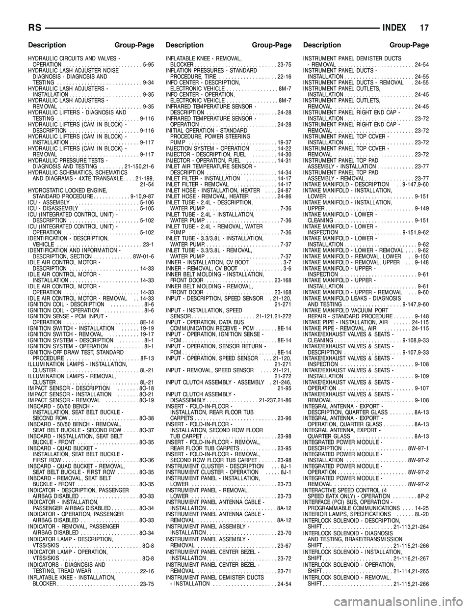
HYDRAULIC CIRCUITS AND VALVES -OPERATION .......................... 5-95
HYDRAULIC LASH ADJUSTER NOISE DIAGNOSIS - DIAGNOSIS AND
TESTING ............................ 9-34
HYDRAULIC LASH ADJUSTERS - INSTALLATION ........................ 9-35
HYDRAULIC LASH ADJUSTERS - REMOVAL ........................... 9-35
HYDRAULIC LIFTERS - DIAGNOSIS AND TESTING ........................... 9-116
HYDRAULIC LIFTERS (CAM IN BLOCK) - DESCRIPTION ....................... 9-116
HYDRAULIC LIFTERS (CAM IN BLOCK) - INSTALLATION ....................... 9-117
HYDRAULIC LIFTERS (CAM IN BLOCK) - REMOVAL .......................... 9-117
HYDRAULIC PRESSURE TESTS - DIAGNOSIS AND TESTING ........21-150,21-6
HYDRAULIC SCHEMATICS, SCHEMATICS AND DIAGRAMS - 4XTE TRANSAXLE ....21-199,
21-54
HYDROSTATIC LOCKED ENGINE, STANDARD PROCEDURE ............9-10,9-87
ICU - ASSEMBLY ..................... 5-106
ICU - DISASSEMBLY ..................5-105
ICU (INTEGRATED CONTROL UNIT) - DESCRIPTION ....................... 5-102
ICU (INTEGRATED CONTROL UNIT) - OPERATION ......................... 5-102
IDENTIFICATION - DESCRIPTION, VEHICLE ............................ 23-1
IDENTIFICATION AND INFORMATION - DESCRIPTION, SECTION ..............8W-01-6
IDLE AIR CONTROL MOTOR - DESCRIPTION ....................... 14-33
IDLE AIR CONTROL MOTOR - INSTALLATION ....................... 14-33
IDLE AIR CONTROL MOTOR - OPERATION ......................... 14-33
IDLE AIR CONTROL MOTOR - REMOVAL . . 14-33
IGNITION COIL - DESCRIPTION ...........8I-6
IGNITION COIL - OPERATION .............8I-6
IGNITION SENSE - PCM INPUT - OPERATION ......................... 8E-14
IGNITION SWITCH - INSTALLATION ......19-19
IGNITION SWITCH - REMOVAL ..........19-17
IGNITION SYSTEM - DESCRIPTION ........8I-1
IGNITION SYSTEM - OPERATION ..........8I-1
IGNITION-OFF DRAW TEST, STANDARD PROCEDURE ........................ 8F-13
ILLUMINATION LAMPS - INSTALLATION, CLUSTER ........................... 8L-21
ILLUMINATION LAMPS - REMOVAL, CLUSTER ........................... 8L-21
IMPACT SENSOR - DESCRIPTION .......8O-18
IMPACT SENSOR - INSTALLATION .......8O-21
IMPACT SENSOR - REMOVAL ...........8O-19
INBOARD - 50/50 BENCH - INSTALLATION, SEAT BELT BUCKLE -
SECOND ROW ....................... 8O-38
INBOARD - 50/50 BENCH - REMOVAL, SEAT BELT BUCKLE - SECOND ROW .....8O-37
INBOARD - INSTALLATION, SEAT BELT BUCKLE - FRONT .................... 8O-35
INBOARD - QUAD BUCKET - INSTALLATION, SEAT BELT BUCKLE -
FIRST ROW ......................... 8O-36
INBOARD - QUAD BUCKET - REMOVAL, SEAT BELT BUCKLE - FIRST ROW .......8O-35
INBOARD - REMOVAL, SEAT BELT BUCKLE - FRONT .................... 8O-35
INDICATOR - DESCRIPTION, PASSENGER AIRBAG DISABLED ................... 8O-33
INDICATOR - INSTALLATION, PASSENGER AIRBAG DISABLED .........8O-34
INDICATOR - OPERATION, PASSENGER AIRBAG DISABLED ................... 8O-33
INDICATOR - REMOVAL, PASSENGER AIRBAG DISABLED ................... 8O-34
INDICATOR LAMP - DESCRIPTION, VTSS/SKIS .......................... 8Q-8
INDICATOR LAMP - OPERATION, VTSS/SKIS .......................... 8Q-8
INDICATORS - DIAGNOSIS AND TESTING, TREAD WEAR ...............22-16
INFLATABLE KNEE - INSTALLATION, BLOCKER ........................... 23-75INFLATABLE KNEE - REMOVAL,
BLOCKER ........................... 23-75
INFLATION PRESSURES - STANDARD PROCEDURE, TIRE ................... 22-16
INFO CENTER - DESCRIPTION, ELECTRONIC VEHICLE .................8M-7
INFO CENTER - OPERATION, ELECTRONIC VEHICLE .................8M-7
INFRARED TEMPERATURE SENSOR - DESCRIPTION ....................... 24-28
INFRARED TEMPERATURE SENSOR - OPERATION ......................... 24-28
INITIAL OPERATION - STANDARD PROCEDURE, POWER STEERING
PUMP ............................. 19-37
INJECTION SYSTEM - OPERATION .......14-22
INJECTOR - DESCRIPTION, FUEL ........14-30
INJECTOR - OPERATION, FUEL ..........14-31
INLET AIR TEMPERATURE SENSOR - DESCRIPTION ....................... 14-34
INLET FILTER - INSTALLATION ..........14-17
INLET FILTER - REMOVAL ..............14-17
INLET HOSE - INSTALLATION, HEATER ....24-87
INLET HOSE - REMOVAL, HEATER .......24-86
INLET TUBE - 2.4L - DESCRIPTION, WATER PUMP ........................ 7-36
INLET TUBE - 2.4L - INSTALLATION, WATER PUMP ........................ 7-36
INLET TUBE - 2.4L - REMOVAL, WATER PUMP .............................. 7-36
INLET TUBE - 3.3/3.8L - INSTALLATION, WATER PUMP ......................... 7-37
INLET TUBE - 3.3/3.8L - REMOVAL, WATER PUMP ........................ 7-37
INNER - INSTALLATION, CV BOOT .........3-7
INNER - REMOVAL, CV BOOT .............3-6
INNER BELT MOLDING - INSTALLATION, FRONT DOOR ...................... 23-168
INNER BELT MOLDING - REMOVAL, FRONT DOOR ...................... 23-168
INPUT - DESCRIPTION, SPEED SENSOR . 21-120, 21-271
INPUT - INSTALLATION, SPEED SENSOR ..................... 21-121,21-272
INPUT - OPERATION, DATA BUS COMMUNICATION RECEIVE - PCM .......8E-14
INPUT - OPERATION, IGNITION SENSE - PCM............................... 8E-14
INPUT - OPERATION, SENSOR RETURN - PCM............................... 8E-14
INPUT - OPERATION, SPEED SENSOR . . . 21-120, 21-271
INPUT - REMOVAL, SPEED SENSOR ....21-121,
21-272
INPUT CLUTCH ASSEMBLY - ASSEMBLY . 21-246, 21-95
INPUT CLUTCH ASSEMBLY - DISASSEMBLY ................. 21-237,21-86
INSERT - FOLD-IN-FLOOR - INSTALLATION, REAR FLOOR TUB
CARPETS ........................... 23-96
INSERT - FOLD-IN-FLOOR - INSTALLATION, SECOND ROW FLOOR
TUB CARPET ........................ 23-98
INSERT - FOLD-IN-FLOOR - REMOVAL, REAR FLOOR TUB CARPETS ............23-95
INSERT - FOLD-IN-FLOOR - REMOVAL, SECOND ROW FLOOR TUB CARPET ......23-98
INSTRUMENT CLUSTER - DESCRIPTION . . . 8J-1
INSTRUMENT CLUSTER - OPERATION .....8J-1
INSTRUMENT PANEL - INSTALLATION, LOWER ............................ 23-73
INSTRUMENT PANEL - REMOVAL, LOWER ............................ 23-73
INSTRUMENT PANEL ANTENNA CABLE - INSTALLATION ....................... 8A-12
INSTRUMENT PANEL ANTENNA CABLE - REMOVAL .......................... 8A-12
INSTRUMENT PANEL ASSEMBLY - INSTALLATION ....................... 23-70
INSTRUMENT PANEL ASSEMBLY - REMOVAL .......................... 23-67
INSTRUMENT PANEL CENTER BEZEL - INSTALLATION ....................... 23-72
INSTRUMENT PANEL CENTER BEZEL - REMOVAL .......................... 23-71
INSTRUMENT PANEL DEMISTER DUCTS - INSTALLATION ..................... 24-54INSTRUMENT PANEL DEMISTER DUCTS
- REMOVAL ......................... 24-54
INSTRUMENT PANEL DUCTS - INSTALLATION ....................... 24-55
INSTRUMENT PANEL DUCTS - REMOVAL . 24-55
INSTRUMENT PANEL OUTLETS, INSTALLATION ....................... 24-45
INSTRUMENT PANEL OUTLETS, REMOVAL .......................... 24-45
INSTRUMENT PANEL RIGHT END CAP - INSTALLATION ....................... 23-72
INSTRUMENT PANEL RIGHT END CAP - REMOVAL .......................... 23-72
INSTRUMENT PANEL TOP COVER - INSTALLATION ....................... 23-72
INSTRUMENT PANEL TOP COVER - REMOVAL .......................... 23-72
INSTRUMENT PANEL TOP PAD ASSEMBLY - INSTALLATION ............23-77
INSTRUMENT PANEL TOP PAD ASSEMBLY - REMOVAL ................23-77
INTAKE MANIFOLD - DESCRIPTION . . 9-147,9-60
INTAKE MANIFOLD - INSTALLATION, LOWER ............................ 9-151
INTAKE MANIFOLD - INSTALLATION, UPPER ............................. 9-149
INTAKE MANIFOLD - LOWER - CLEANING .......................... 9-151
INTAKE MANIFOLD - LOWER - INSPECTION .................... 9-151,9-62
INTAKE MANIFOLD - LOWER - INSTALLATION ........................ 9-62
INTAKE MANIFOLD - LOWER - REMOVAL ....9-62
INTAKE MANIFOLD - REMOVAL, LOWER . . 9-150
INTAKE MANIFOLD - REMOVAL, UPPER . . . 9-148
INTAKE MANIFOLD - UPPER - INSPECTION ......................... 9-61
INTAKE MANIFOLD - UPPER - INSTALLATION ........................ 9-61
INTAKE MANIFOLD - UPPER - REMOVAL . . . 9-60
INTAKE MANIFOLD LEAKS - DIAGNOSIS AND TESTING ................... 9-147,9-60
INTAKE MANIFOLD VACUUM PORT REPAIR - STANDARD PROCEDURE .......9-148
INTAKE PIPE - INSTALLATION, AIR ......24-115
INTAKE PIPE - REMOVAL, AIR .........24-115
INTAKE/EXHAUST VALVES & SEATS - CLEANING ...................... 9-108,9-33
INTAKE/EXHAUST VALVES & SEATS - DESCRIPTION ................... 9-107,9-33
INTAKE/EXHAUST VALVES & SEATS - INSPECTION ........................ 9-108
INTAKE/EXHAUST VALVES & SEATS - INSTALLATION ....................... 9-109
INTAKE/EXHAUST VALVES & SEATS - OPERATION ......................... 9-107
INTAKE/EXHAUST VALVES & SEATS - REMOVAL .......................... 9-108
INTEGRAL ANTENNA - EXPORT - DESCRIPTION, QUARTER GLASS ........8A-13
INTEGRAL ANTENNA - EXPORT - OPERATION, QUARTER GLASS ..........8A-13
INTEGRAL ANTENNA, EXPORT - QUARTER GLASS .................... 8A-13
INTEGRATED POWER MODULE - DESCRIPTION .....................8W -97-1
INTEGRATED POWER MODULE - INSTALLATION ....................8W -97-2
INTEGRATED POWER MODULE - OPERATION .......................8W -97-2
INTEGRATED POWER MODULE - REMOVAL ........................8W -97-2
INTERACTIVE SPEED CONTROL (4 SPEED EATX ONLY) - OPERATION ........8P-2
INTERFACE (PCI) BUS, OPERATION - PROGRAMMABLE COMMUNICATIONS ....14-25
INTERIOR LAMPS, SPECIFICATIONS ......8L-20
INTERLOCK SOLENOID - DESCRIPTION, SHIFT ....................... 21-113,21-264
INTERLOCK SOLENOID - DIAGNOSIS AND TESTING, BRAKE/TRANSMISSION
SHIFT ....................... 21-115,21-266
INTERLOCK SOLENOID - INSTALLATION, SHIFT ....................... 21-116,21-267
INTERLOCK SOLENOID - OPERATION, SHIFT ....................... 21-114,21-265
INTERLOCK SOLENOID - REMOVAL, SHIFT ....................... 21-115,21-266
RS INDEX17
Description Group-Page Description Group-Page Description Group-Page
Page 2327 of 2339
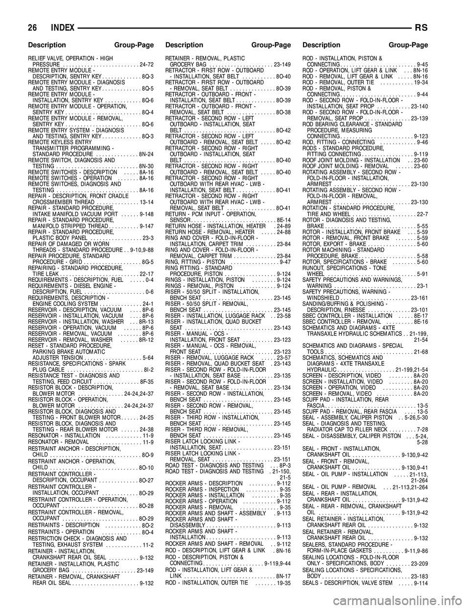
RELIEF VALVE, OPERATION - HIGHPRESSURE ......................... 24-72
REMOTE ENTRY MODULE - DESCRIPTION, SENTRY KEY .............8Q-3
REMOTE ENTRY MODULE - DIAGNOSIS AND TESTING, SENTRY KEY .............8Q-5
REMOTE ENTRY MODULE - INSTALLATION, SENTRY KEY ............8Q-6
REMOTE ENTRY MODULE - OPERATION, SENTRY KEY ......................... 8Q-4
REMOTE ENTRY MODULE - REMOVAL, SENTRY KEY ......................... 8Q-6
REMOTE ENTRY SYSTEM - DIAGNOSIS AND TESTING, SENTRY KEY .............8Q-3
REMOTE KEYLESS ENTRY TRANSMITTER PROGRAMMING -
STANDARD PROCEDURE ..............8N-24
REMOTE SWITCH, DIAGNOSIS AND TESTING ........................... 8N-30
REMOTE SWITCHES - DESCRIPTION .....8A-16
REMOTE SWITCHES - OPERATION .......8A-16
REMOTE SWITCHES, DIAGNOSIS AND TESTING ........................... 8A-16
REPAIR - DESCRIPTION, FRONT CRADLE CROSSMEMBER THREAD ..............13-14
REPAIR - STANDARD PROCEDURE, INTAKE MANIFOLD VACUUM PORT ......9-148
REPAIR - STANDARD PROCEDURE, MANIFOLD STRIPPED THREAD ..........9-147
REPAIR - STANDARD PROCEDURE, PLASTIC BODY PANEL .................23-3
REPAIR OF DAMAGED OR WORN THREADS - STANDARD PROCEDURE . . 9-10,9-88
REPAIR PROCEDURE, STANDARD PROCEDURE - GRID ................... 8G-5
REPAIRING - STANDARD PROCEDURE, TIRE LEAK .......................... 22-17
REQUIREMENTS - DESCRIPTION, FUEL .....0-4
REQUIREMENTS - DIESEL ENGINE - DESCRIPTION, FUEL ....................0-6
REQUIREMENTS, DESCRIPTION - ENGINE COOLING SYSTEM ..............24-1
RESERVOIR - DESCRIPTION, VACUUM ....8P-6
RESERVOIR - INSTALLATION, VACUUM ....8P-6
RESERVOIR - INSTALLATION, WASHER . . . 8R-13
RESERVOIR - OPERATION, VACUUM ......8P-6
RESERVOIR - REMOVAL, VACUUM ........8P-6
RESERVOIR - REMOVAL, WASHER ......8R-12
RESET - STANDARD PROCEDURE, PARKING BRAKE AUTOMATIC
ADJUSTER TENSION ................... 5-64
RESISTANCE, SPECIFICATIONS - SPARK PLUG CABLE ......................... 8I-2
RESISTANCE TEST - DIAGNOSIS AND TESTING, FEED CIRCUIT ...............8F-35
RESISTOR BLOCK - DESCRIPTION, BLOWER MOTOR ............... 24-24,24-37
RESISTOR BLOCK - OPERATION, BLOWER MOTOR ............... 24-24,24-37
RESISTOR BLOCK, DIAGNOSIS AND TESTING - FRONT BLOWER MOTOR ......24-25
RESISTOR BLOCK, DIAGNOSIS AND TESTING - REAR BLOWER MOTOR ......24-38
RESONATOR - INSTALLATION ............11-9
RESONATOR - REMOVAL ...............11-9
RESTRAINT ANCHOR - DESCRIPTION, CHILD .............................. 8O-9
RESTRAINT ANCHOR - OPERATION, CHILD ............................. 8O-10
RESTRAINT CONTROLLER - DESCRIPTION, OCCUPANT .............8O-27
RESTRAINT CONTROLLER - INSTALLATION, OCCUPANT ............8O-29
RESTRAINT CONTROLLER - OPERATION, OCCUPANT ......................... 8O-28
RESTRAINT CONTROLLER - REMOVAL, OCCUPANT ......................... 8O-29
RESTRAINTS - DESCRIPTION ............8O-2
RESTRAINTS - OPERATION .............8O-4
RESTRICTION CHECK - DIAGNOSIS AND TESTING, EXHAUST SYSTEM ............11-2
RETAINER - INSTALLATION, CRANKSHAFT REAR OIL SEAL ..........9-132
RETAINER - INSTALLATION, PLASTIC GROCERY BAG ..................... 23-149
RETAINER - REMOVAL, CRANKSHAFT REAR OIL SEAL ...................... 9-132RETAINER - REMOVAL, PLASTIC
GROCERY BAG ..................... 23-149
RETRACTOR - FIRST ROW - OUTBOARD - INSTALLATION, SEAT BELT ...........8O-40
RETRACTOR - FIRST ROW - OUTBOARD - REMOVAL, SEAT BELT ...............8O-39
RETRACTOR - OUTBOARD - FRONT - INSTALLATION, SEAT BELT .............8O-39
RETRACTOR - OUTBOARD - FRONT - REMOVAL, SEAT BELT ................8O-38
RETRACTOR - SECOND ROW - LEFT OUTBOARD - INSTALLATION, SEAT
BELT .............................. 8O-42
RETRACTOR - SECOND ROW - LEFT OUTBOARD - REMOVAL, SEAT BELT .....8O-42
RETRACTOR - SECOND ROW - RIGHT OUTBOARD - INSTALLATION, SEAT
BELT .............................. 8O-40
RETRACTOR - SECOND ROW - RIGHT OUTBOARD - REMOVAL, SEAT BELT .....8O-40
RETRACTOR - SECOND ROW - RIGHT OUTBOARD WITH REAR HVAC - LWB -
INSTALLATION, SEAT BELT .............8O-41
RETRACTOR - SECOND ROW - RIGHT OUTBOARD WITH REAR HVAC - LWB -
REMOVAL, SEAT BELT ................8O-41
RETURN - PCM INPUT - OPERATION, SENSOR ............................ 8E-14
RETURN HOSE - INSTALLATION, HEATER . 24-89
RETURN HOSE - REMOVAL, HEATER .....24-88
RING AND COVER - FOLD-IN-FLOOR - INSTALLATION, CARPET TRIM ..........23-84
RING AND COVER - FOLD-IN-FLOOR - REMOVAL, CARPET TRIM ..............23-84
RING, FITTING - PISTON ................9-47
RING FITTING - STANDARD PROCEDURE, PISTON .................9-124
RINGS - INSTALLATION, PISTON ........9-124
RINGS - REMOVAL, PISTON ............9-124
RISER - 50/50 SPLIT - INSTALLATION, BENCH SEAT ....................... 23-145
RISER - 50/50 SPLIT - REMOVAL, BENCH SEAT ....................... 23-145
RISER - INSTALLATION, LUGGAGE RACK . . 23-58
RISER - INSTALLATION, QUAD BUCKET SEAT ............................. 23-143
RISER - MANUAL - OCS - INSTALLATION, FRONT SEAT ..........23-123
RISER - MANUAL - OCS - REMOVAL, FRONT SEAT ....................... 23-123
RISER - REMOVAL, LUGGAGE RACK .....23-57
RISER - REMOVAL, QUAD BUCKET SEAT . 23-143
RISER - SECOND ROW - FOLD-IN-FLOOR - INSTALLATION, SEAT BASE ..........23-135
RISER - SECOND ROW - FOLD-IN-FLOOR - REMOVAL, SEAT BASE ..............23-134
RISER - SECOND ROW - INSTALLATION, BENCH SEAT ....................... 23-145
RISER - SECOND ROW - REMOVAL, BENCH SEAT ....................... 23-145
RISER - THIRD ROW - INSTALLATION, BENCH SEAT ....................... 23-145
RISER - THIRD ROW - REMOVAL, BENCH SEAT ....................... 23-145
RISER LATCH LOCKING LINK - INSTALLATION, SEAT .................23-151
RISER LATCH LOCKING LINK - REMOVAL, SEAT .................... 23-151
ROAD TEST - DIAGNOSIS AND TESTING . . . 8P-3
ROAD TEST - DIAGNOSIS AND TESTING . 21-150, 21-5
ROCKER ARMS - DESCRIPTION .........9-112
ROCKER ARMS - INSPECTION ...........9-35
ROCKER ARMS - INSTALLATION .........9-35
ROCKER ARMS - OPERATION ...........9-112
ROCKER ARMS - REMOVAL .............9-35
ROCKER ARMS AND SHAFT - ASSEMBLY . 9-113
ROCKER ARMS AND SHAFT - DISASSEMBLY ....................... 9-113
ROCKER ARMS AND SHAFT - INSTALLATION ....................... 9-113
ROCKER ARMS AND SHAFT - REMOVAL . . 9-112
ROD - DESCRIPTION, LIFT GEAR & LINK . 8N-16
ROD - DESCRIPTION, PISTON & CONNECTING .................... 9-119,9-44
ROD - INSTALLATION, LIFT GEAR & LINK .............................. 8N-17
ROD - INSTALLATION, OUTER TIE .......19-35 ROD - INSTALLATION, PISTON &
CONNECTING ......................... 9-45
ROD - OPERATION, LIFT GEAR & LINK . . . 8N-16
ROD - REMOVAL, LIFT GEAR & LINK .....8N-16
ROD - REMOVAL, OUTER TIE ...........19-34
ROD - REMOVAL, PISTON & CONNECTING ......................... 9-44
ROD - SECOND ROW - FOLD-IN-FLOOR - INSTALLATION, SEAT PROP ...........23-140
ROD - SECOND ROW - FOLD-IN-FLOOR - REMOVAL, SEAT PROP ...............23-139
ROD BEARING CLEARANCE - STANDARD PROCEDURE, MEASURING
CONNECTING ........................ 9-123
ROD, FITTING - CONNECTING ............9-46
RODS - STANDARD PROCEDURE, FITTING CONNECTING .................9-119
ROOF JOINT MOLDING - INSTALLATION . . 23-60
ROOF JOINT MOLDING - REMOVAL ......23-60
ROTATING ASSEMBLY - SECOND ROW - FOLD-IN-FLOOR - INSTALLATION,
ARMREST ......................... 23-130
ROTATING ASSEMBLY - SECOND ROW - FOLD-IN-FLOOR - REMOVAL,
ARMREST ......................... 23-130
ROTATION - STANDARD PROCEDURE, TIRE AND WHEEL ..................... 22-7
ROTOR - DIAGNOSIS AND TESTING, BRAKE .............................. 5-55
ROTOR - INSTALLATION, FRONT BRAKE . . . 5-59
ROTOR - REMOVAL, FRONT BRAKE .......5-59
ROTOR, EXPORT - BRAKE ................5-60
ROTOR MACHINING - STANDARD PROCEDURE, BRAKE ................... 5-58
ROTOR, SPECIFICATIONS - BRAKE ........5-60
RUNOUT, SPECIFICATIONS - TONE WHEEL ............................. 5-91
SAFETY PRECAUTIONS AND WARNINGS, WARNING ........................... 23-1
SAFETY PRECAUTIONS, WARNING - WINDSHIELD ....................... 23-161
SANDING/BUFFING & POLISHING - DESCRIPTION, FINESSE ..............23-101
SBEC CONTROLLER - INSTALLATION .....8E-17
SBEC CONTROLLER - REMOVAL .........8E-16
SCHEMATICS AND DIAGRAMS - 4XTE TRANSAXLE HYDRAULIC SCHEMATICS . . 21-199, 21-54
SCHEMATICS AND DIAGRAMS - SPECIAL TOOLS ............................. 21-68
SCHEMATICS, SCHEMATICS AND DIAGRAMS - 4XTE TRANSAXLE
HYDRAULIC ................... 21-199,21-54
SCREEN - DESCRIPTION, VIDEO ........8A-20
SCREEN - INSTALLATION, VIDEO ........8A-20
SCREEN - OPERATION, VIDEO ..........8A-20
SCREEN - REMOVAL, VIDEO ............8A-20
SCUFF PAD - INSTALLATION, REAR FASCIA .............................. 13-5
SCUFF PAD - REMOVAL, REAR FASCIA ....13-5
SEAL - ASSEMBLY, CALIPER PISTON . . 5-26,5-30
SEAL - DIAGNOSIS AND TESTING, RADIATOR CAP TO FILLER NECK .........7-28
SEAL - DISASSEMBLY, CALIPER PISTON . . . 5-24,
5-28
SEAL - FRONT - INSTALLATION, CRANKSHAFT OIL ................ 9-130,9-42
SEAL - FRONT - REMOVAL, CRANKSHAFT OIL ................ 9-130,9-41
SEAL - OIL PUMP - INSTALLATION .....21-113,
21-264
SEAL - OIL PUMP - REMOVAL . . . 21-113,21-264
SEAL - REAR - INSTALLATION, CRANKSHAFT OIL ................ 9-131,9-42
SEAL - REAR - REMOVAL, CRANKSHAFT OIL ........................... 9-131,9-42
SEAL RETAINER - INSTALLATION, CRANKSHAFT REAR OIL ...............9-132
SEAL RETAINER - REMOVAL, CRANKSHAFT REAR OIL ...............9-132
SEALERS, STANDARD PROCEDURE - FORM-IN-PLACE GASKETS ..........9-11,9-86
SEALING LOCATIONS - FOLD-IN-FLOOR ONLY - SPECIFICATIONS, BODY ........23-209
SEALING LOCATIONS - SPECIFICATIONS, BODY ............................. 23-183
SEALS - DESCRIPTION, VALVE STEM .....9-114
26 INDEXRS
Description Group-Page Description Group-Page Description Group-Page