diagram CHRYSLER CARAVAN 2005 Owner's Guide
[x] Cancel search | Manufacturer: CHRYSLER, Model Year: 2005, Model line: CARAVAN, Model: CHRYSLER CARAVAN 2005Pages: 2339, PDF Size: 59.69 MB
Page 552 of 2339
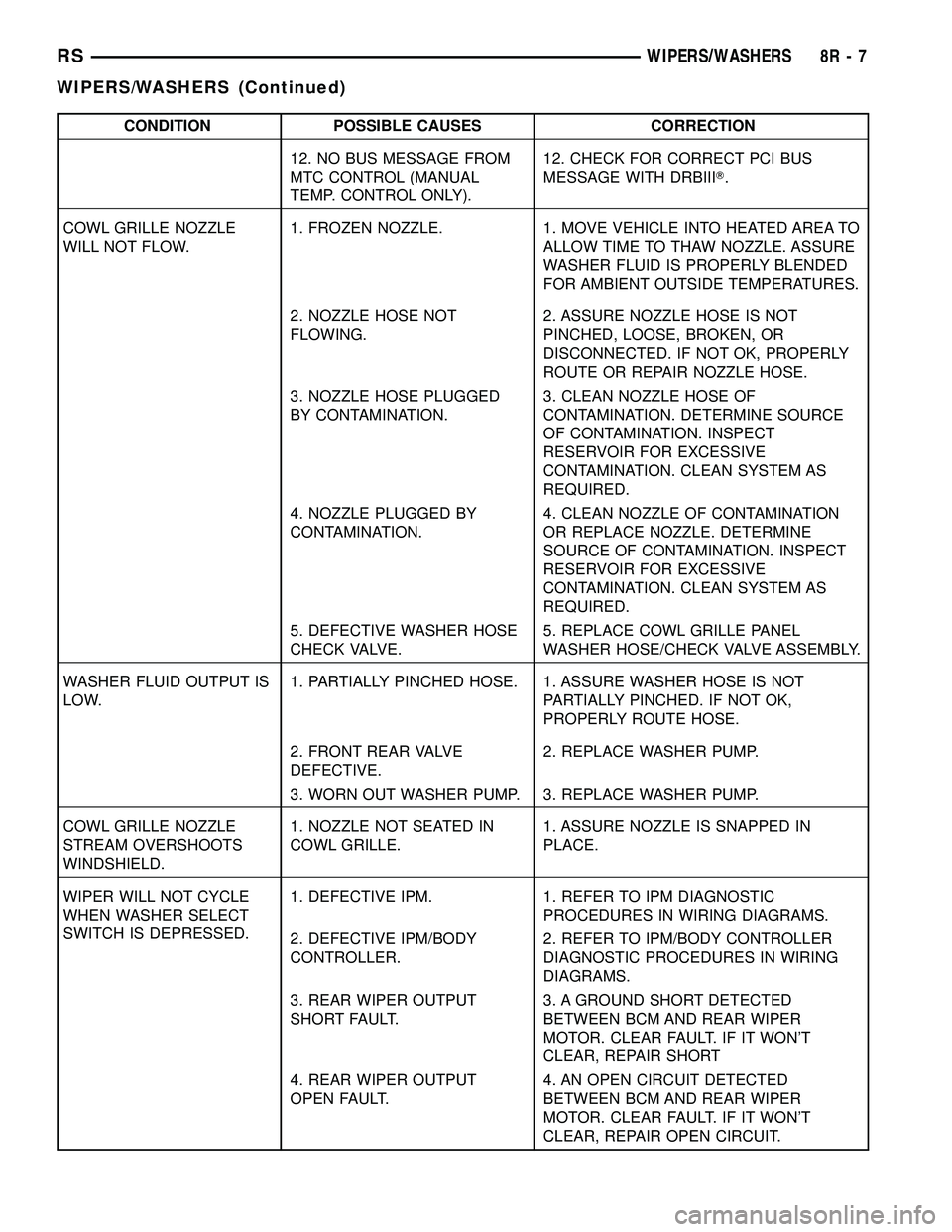
CONDITION POSSIBLE CAUSES CORRECTION
12. NO BUS MESSAGE FROM
MTC CONTROL (MANUAL
TEMP. CONTROL ONLY).12. CHECK FOR CORRECT PCI BUS
MESSAGE WITH DRBIIIT.
COWL GRILLE NOZZLE
WILL NOT FLOW.1. FROZEN NOZZLE. 1. MOVE VEHICLE INTO HEATED AREA TO
ALLOW TIME TO THAW NOZZLE. ASSURE
WASHER FLUID IS PROPERLY BLENDED
FOR AMBIENT OUTSIDE TEMPERATURES.
2. NOZZLE HOSE NOT
FLOWING.2. ASSURE NOZZLE HOSE IS NOT
PINCHED, LOOSE, BROKEN, OR
DISCONNECTED. IF NOT OK, PROPERLY
ROUTE OR REPAIR NOZZLE HOSE.
3. NOZZLE HOSE PLUGGED
BY CONTAMINATION.3. CLEAN NOZZLE HOSE OF
CONTAMINATION. DETERMINE SOURCE
OF CONTAMINATION. INSPECT
RESERVOIR FOR EXCESSIVE
CONTAMINATION. CLEAN SYSTEM AS
REQUIRED.
4. NOZZLE PLUGGED BY
CONTAMINATION.4. CLEAN NOZZLE OF CONTAMINATION
OR REPLACE NOZZLE. DETERMINE
SOURCE OF CONTAMINATION. INSPECT
RESERVOIR FOR EXCESSIVE
CONTAMINATION. CLEAN SYSTEM AS
REQUIRED.
5. DEFECTIVE WASHER HOSE
CHECK VALVE.5. REPLACE COWL GRILLE PANEL
WASHER HOSE/CHECK VALVE ASSEMBLY.
WASHER FLUID OUTPUT IS
LOW.1. PARTIALLY PINCHED HOSE. 1. ASSURE WASHER HOSE IS NOT
PARTIALLY PINCHED. IF NOT OK,
PROPERLY ROUTE HOSE.
2. FRONT REAR VALVE
DEFECTIVE.2. REPLACE WASHER PUMP.
3. WORN OUT WASHER PUMP. 3. REPLACE WASHER PUMP.
COWL GRILLE NOZZLE
STREAM OVERSHOOTS
WINDSHIELD.1. NOZZLE NOT SEATED IN
COWL GRILLE.1. ASSURE NOZZLE IS SNAPPED IN
PLACE.
WIPER WILL NOT CYCLE
WHEN WASHER SELECT
SWITCH IS DEPRESSED.1. DEFECTIVE IPM. 1. REFER TO IPM DIAGNOSTIC
PROCEDURES IN WIRING DIAGRAMS.
2. DEFECTIVE IPM/BODY
CONTROLLER.2. REFER TO IPM/BODY CONTROLLER
DIAGNOSTIC PROCEDURES IN WIRING
DIAGRAMS.
3. REAR WIPER OUTPUT
SHORT FAULT.3. A GROUND SHORT DETECTED
BETWEEN BCM AND REAR WIPER
MOTOR. CLEAR FAULT. IF IT WON'T
CLEAR, REPAIR SHORT
4. REAR WIPER OUTPUT
OPEN FAULT.4. AN OPEN CIRCUIT DETECTED
BETWEEN BCM AND REAR WIPER
MOTOR. CLEAR FAULT. IF IT WON'T
CLEAR, REPAIR OPEN CIRCUIT.
RSWIPERS/WASHERS8R-7
WIPERS/WASHERS (Continued)
Page 553 of 2339

CONDITION POSSIBLE CAUSES CORRECTION
5. NO BUS MESSAGE FROM
MTC CONTROL (MANUAL
TEMP. CONTROL ONLY).5. REFER TO PROPER BODY DIAGNOSTIC
INFORMATION OR USE DRBIIITTO CHECK
PROPER MESSAGE STATUS.
WASHER OPERATES
INTERMITTENTLY.1. INTERMITTENT MOTOR
GROUND.INTERMITTENT GROUND BETWEEN
MOTOR CONNECTOR TERMINAL 1 AND
IPM PIN 20.
2. INTERMITTENT OPEN IN
WASHER SELECT SWITCH.2. (Refer to 8 - ELECTRICAL/LAMPS/
LIGHTING - EXTERIOR/MULTI-FUNCTION
SWITCH - DIAGNOSIS AND TESTING).
3. DEFECTIVE WASHER
MOTOR.3. REPLACE WASHER PUMP.
LOW WASHER FLUID
LEVEL INDICATOR
INOPERATIVE.1. LOOSE FLUID LEVEL
SENSOR CONNECTOR.1. PROPERLY SEAT CONNECTOR TO LOW
FLUID LEVEL SENSOR AND LOCK.
2. OPEN POWER CIRCUIT TO
FLUID LEVEL SENSOR.2. OPEN OR DEFECTIVE CIRCUIT
BETWEEN IPM CONNECTOR TERMINAL 7
AND THE LOW FLUID LEVEL SENSOR
CONNECTOR TERMINAL 2. IF NOT OK,
REPAIR CIRCUIT.
3. OPEN GROUND CIRCUIT. 3. OPEN OR DEFECTIVE CIRCUIT
BETWEEN FLUID LEVEL SENSOR
CONNECTOR TERMINAL 1 AND FLOOR
GROUND 1.
4. DEFECTIVE IPM. 4. REFER TO IPM DIAGNOSTIC
PROCEDURES IN WIRING DIAGRAMS.
5. FLUID LEVEL SENSOR
SWITCH OPEN OR
DEFECTIVE.5. APPLY OHMMETER TO THE SWITCH
TERMINALS TO CHECK FOR COMPLETE
CIRCUIT. CYCLE SWITCH FLOAT BACK
AND FORTH BY FILLING AND DEPLETING
RESERVOIR OF WASHER FLUID TO
CHECK FOR PROPER SWITCH FUNCTION.
IF NOT OK, REPLACE LOW FLUID LEVEL
SENSOR SWITCH.
LEAKING WASHER FLUID. 1. PUMP OR SENSOR
GROMMET DEFECTIVE.1. PROPERLY SEAT PUMP OR SENSOR IN
GROMMET. IF NOT OK, REPLACE PUMP
OR SENSOR GROMMET.
2. LEAKING WASHER PUMP. 2. REPLACE WASHER PUMP.
3. LEAKING FLUID LEVEL
SENSOR.3. REPLACE FLUID LEVEL SENSOR.
4. LEAKING OR DEFECTIVE
RESERVOIR BODY.4. REPLACE RESERVOIR BODY.
8R - 8 WIPERS/WASHERSRS
WIPERS/WASHERS (Continued)
Page 560 of 2339
NAVIGATION/TELECOMMUNICATION
TABLE OF CONTENTS
page page
NAVIGATION/TELECOMMUNICATION
DESCRIPTION..........................1
OPERATION............................1
DIAGNOSIS AND TESTING
TELECOMMUNICATION.................1HANDS FREE MODULE
REMOVAL.............................3
INSTALLATION..........................3
NAVIGATION/
TELECOMMUNICATION
DESCRIPTION
TELECOMMUNICATIONS
A hands-free cellular system is an available option
on this vehicle. It uses BluetoothŸ technology to pro-
vide wireless communication between the operator's
compatible cellular telephone and the vehicle's
on-board receiver.
The system uses voice recognition technology to
control operation. The incoming voice is broadcast
through the vehicle's radio speakers, automatically
overriding any other audio signals on the speakers
when the hands-free system is in use. A microphone
in the rearview mirror picks up vehicle occupant's
voices. If a call is in progress when the ignition is
switched off, the hands-free system will continue to
operate for up to 45 seconds as part of the Accessory
Relay Delay function. Thereafter, the call can con-
tinue on the hand-held telephone.
The center console front storage compartment
includes a cellular telephone holder, but the system
will communicate with a telephone that is anywhere
within the vehicle. However, covering the hand held
phone or the hands-free phone module with a metal
object may block the signal. The system will recog-
nize up to seven telephones, each of which is given a
spoken identification by the user during the setup
process. The system includes Spanish voice recogni-
tion in addition to English.
Two buttons on the rearview mirror, identified with
ISO icons, control the system: A9phone9button turns
the system on and off; a9voice recognition9(or voice
command) button prompts the hands-free system to
listen for a voice command.
OPERATION
TELECOMMUNICATION
Two buttons on the rearview mirror, identified with
ISO icons, control the system: A9phone9button turns
the system on and off; a9voice recognition9(or voice
command) button prompts the hands-free system to
listen for a voice command. The system includes the
following features:
²Phonebook - Stores telephone numbers for later
recall by name or other verbal identification, called a
voice tag, and memory location.
²Four memory locations - Home, Work, Mobile
and Pager. A maximum of 32 unique names or voice
tags may be stored at the same time, with a different
number in each of the four memory locations.
²Voice tag dialing - Dials the number associated
with a voice tag and memory location.
²Digit dialing - Dials the telephone number by
recognizing the names of the digits as they are spo-
ken.
²Receiving calls - A voice prompt notifies the user
of an incoming call. Pressing the ªphoneº button
answers the call.
²Privacy Mode - Switches the call to the hand-
held telephone and the hands-free system and back
again using the ªvoice recognitionº (or ªvoice com-
mandº) button and a voice command, if desired.
DIAGNOSIS AND TESTING
TELECOMMUNICATION
Any diagnosis of the Telecommunication sys-
tem should begin with the use of the DRB IIIt
diagnostic tool. For information on the use of
the DRB IIIt, refer to the appropriate Diagnos-
tic Service Information.
For complete circuit diagrams, refer to the appro-
priate wiring information.
RSNAVIGATION/TELECOMMUNICATION8T-1
Page 564 of 2339
WIRING
TABLE OF CONTENTS
page page
WIRING DIAGRAM INFORMATION....... 8W-01-1
COMPONENT INDEX.................. 8W-02-1
POWER DISTRIBUTION............... 8W-10-1
GROUND DISTRIBUTION.............. 8W-15-1
BUS COMMUNICATIONS.............. 8W-18-1
CHARGING SYSTEM.................. 8W-20-1
STARTING SYSTEM.................. 8W-21-1
FUEL/IGNITION SYSTEM.............. 8W-30-1
TRANSMISSION CONTROL SYSTEM..... 8W-31-1
VEHICLE SPEED CONTROL............ 8W-33-1
ANTILOCK BRAKES................... 8W-35-1
VEHICLE THEFT SECURITY SYSTEM..... 8W-39-1
INSTRUMENT CLUSTER............... 8W-40-1
HORN/CIGAR LIGHTER/POWER OUTLET . . 8W-41-1
AIR CONDITIONING-HEATER........... 8W-42-1
OCCUPANT RESTRAINT SYSTEM........ 8W-43-1
INTERIOR LIGHTING.................. 8W-44-1
BODY CONTROL MODULE............. 8W-45-1
MESSAGE CENTER................... 8W-46-1
AUDIO SYSTEM..................... 8W-47-1REAR WINDOW DEFOGGER............ 8W-48-1
OVERHEAD CONSOLE................. 8W-49-1
FRONT LIGHTING.................... 8W-50-1
REAR LIGHTING..................... 8W-51-1
TURN SIGNALS...................... 8W-52-1
WIPERS............................ 8W-53-1
TRAILER TOW....................... 8W-54-1
NAVIGATION/TELECOMMUNICATIONS.... 8W-55-1
CONVENIENCE SYSTEMS.............. 8W-56-1
POWER WINDOWS................... 8W-60-1
POWER DOOR LOCKS................ 8W-61-1
POWER MIRRORS................... 8W-62-1
POWER SEATS...................... 8W-63-1
POWER SUNROOF................... 8W-64-1
SPLICE INFORMATION................ 8W-70-1
CONNECTOR PIN-OUTS............... 8W-80-1
CONNECTOR/GROUND/SPLICE
LOCATION........................ 8W-91-1
POWER DISTRIBUTION SYSTEM........ 8W-97-1 RSWIRING
8W-1
Page 566 of 2339

8W-01 WIRING DIAGRAM INFORMATION
TABLE OF CONTENTS
page page
WIRING DIAGRAM INFORMATION
DESCRIPTION
DESCRIPTION - HOW TO USE WIRING
DIAGRAMS...........................1
DESCRIPTION - CIRCUIT INFORMATION....5
DESCRIPTION - CIRCUIT FUNCTIONS......6
DESCRIPTION - SECTION IDENTIFICATION
AND INFORMATION....................6
DESCRIPTION - CONNECTOR, GROUND
AND SPLICE INFORMATION..............7
WARNING
WARNINGS - GENERAL.................7
DIAGNOSIS AND TESTING - WIRING
HARNESS............................7
STANDARD PROCEDURE
STANDARD PROCEDURE -
ELECTROSTATIC DISCHARGE (ESD)
SENSITIVE DEVICES...................8
STANDARD PROCEDURE - TESTING OF
VOLTAGE POTENTIAL...................9
STANDARD PROCEDURE - TESTING FOR
CONTINUITY..........................9STANDARD PROCEDURE - TESTING FOR A
SHORT TO GROUND...................9
STANDARD PROCEDURE - TESTING FOR A
SHORT TO GROUND ON FUSES
POWERING SEVERAL LOADS...........10
STANDARD PROCEDURE - TESTING FOR A
VOLTAGE DROP......................10
SPECIAL TOOLS
WIRING/TERMINAL....................10
CONNECTOR
REMOVAL.............................11
INSTALLATION.........................11
DIODE
REMOVAL.............................14
INSTALLATION.........................14
TERMINAL
REMOVAL.............................14
INSTALLATION.........................14
WIRE
STANDARD PROCEDURE - WIRE SPLICING . . 15
WIRING DIAGRAM
INFORMATION
DESCRIPTION
DESCRIPTION - HOW TO USE WIRING
DIAGRAMS
DaimlerChrysler Corporation wiring diagrams are
designed to provide information regarding the vehi-
cles wiring content. In order to effectively use the
wiring diagrams to diagnose and repair
DaimlerChrysler Corporation vehicles, it is important
to understand all of their features and characteris-
tics.
Diagrams are arranged such that the power (B+)
side of the circuit is placed near the top of the page,
and the ground (B-) side of the circuit is placed near
the bottom of the page (Fig. 1).
All switches, components, and modules are shown
in the at rest position with the doors closed and the
key removed from the ignition (Fig. 2).Components are shown two ways. A solid line
around a component indicates that the component is
complete. A dashed line around the component indi-
cates that the component is being shown is not com-
plete. Incomplete components have a reference
number to indicate the page where the component is
shown complete.
It is important to realize that no attempt is made
on the diagrams to represent components and wiring
as they appear on the vehicle. For example, a short
piece of wire is treated the same as a long one. In
addition, switches and other components are shown
as simply as possible, with regard to function only.
SYMBOLS
International symbols are used throughout the wir-
ing diagrams. These symbols are consistent with
those being used around the world (Fig. 3).
RS8W-01 WIRING DIAGRAM INFORMATION8W-01-1
Page 567 of 2339
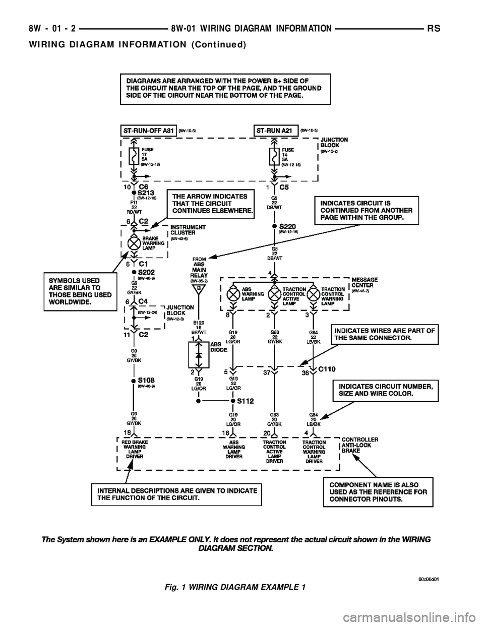
Fig. 1 WIRING DIAGRAM EXAMPLE 1
8W - 01 - 2 8W-01 WIRING DIAGRAM INFORMATIONRS
WIRING DIAGRAM INFORMATION (Continued)
Page 568 of 2339
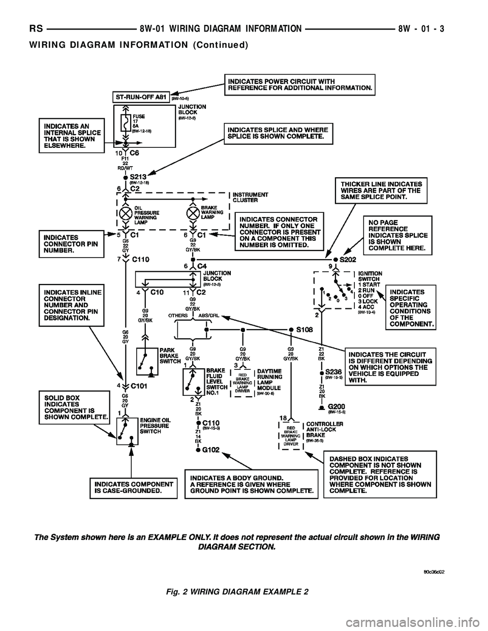
Fig. 2 WIRING DIAGRAM EXAMPLE 2
RS8W-01 WIRING DIAGRAM INFORMATION8W-01-3
WIRING DIAGRAM INFORMATION (Continued)
Page 569 of 2339
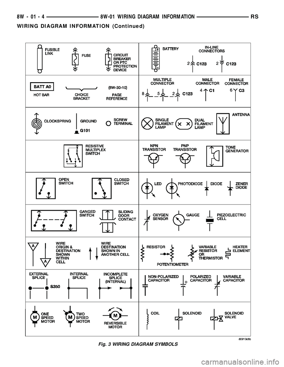
Fig. 3 WIRING DIAGRAM SYMBOLS
8W - 01 - 4 8W-01 WIRING DIAGRAM INFORMATIONRS
WIRING DIAGRAM INFORMATION (Continued)
Page 570 of 2339

TERMINOLOGY
This is a list of terms and definitions used in the
wiring diagrams.
LHD.................Left Hand Drive Vehicles
RHD ...............Right Hand Drive Vehicles
ATX . . Automatic Transmissions-Front Wheel Drive
MTX . . . Manual Transmissions-Front Wheel Drive
AT....Automatic Transmissions-Rear Wheel Drive
MT .....Manual Transmissions-Rear Wheel Drive
SOHC...........Single Over Head Cam Engine
DOHC..........Double Over Head Cam Engine
Export . . Vehicles Built For Sale In Markets Other
Than North America
Except Export.... Vehicles Built For Sale In North
America
DESCRIPTION - CIRCUIT INFORMATION
Each wire shown in the diagrams contains a code
which identifies the main circuit, part of the main
circuit, gage of wire, and color (Fig. 4).
WIRE COLOR CODE CHART
COLOR CODE COLOR
BL BLUE
BK BLACK
BR BROWN
DB DARK BLUE
DG DARK GREEN
GY GRAY
LB LIGHT BLUE
LG LIGHT GREEN
OR ORANGE
PK PINK
RD RED
TN TAN
VT VIOLET
WT WHITE
YL YELLOW
* WITH TRACER
Fig. 4 WIRE CODE IDENTIFICATION
1 - COLOR OF WIRE (LIGHT BLUE WITH YELLOW TRACER
2 - GAGE OF WIRE (18 GAGE)
3 - PART OF MAIN CIRCUIT (VARIES DEPENDING ON
EQUIPMENT)
4 - MAIN CIRCUIT IDENTIFICATION
RS8W-01 WIRING DIAGRAM INFORMATION8W-01-5
WIRING DIAGRAM INFORMATION (Continued)
Page 571 of 2339

DESCRIPTION - CIRCUIT FUNCTIONS
All circuits in the diagrams use an alpha/numeric
code to identify the wire and it's function. To identify
which circuit code applies to a system, refer to the
Circuit Identification Code Chart. This chart shows
the main circuits only and does not show the second-
ary codes that may apply to some models.
CIRCUIT IDENTIFICATION CODE CHART
CIRCUIT FUNCTION
A BATTERY FEED
B BRAKE CONTROLS
C CLIMATE CONTROLS
D DIAGNOSTIC CIRCUITS
E DIMMING ILLUMINATION
CIRCUITS
F FUSED CIRCUITS
G MONITORING CIRCUITS
(GAUGES)
H MULTIPLE
I NOT USED
J OPEN
K POWERTRAIN CONTROL
MODULE
L EXTERIOR LIGHTING
M INTERIOR LIGHTING
N MULTIPLE
O NOT USED
P POWER OPTION (BATTERY
FEED)
Q POWER OPTIONS (IGNITION
FEED)
R PASSIVE RESTRAINT
S SUSPENSION/STEERING
T TRANSMISSION/TRANSAXLE/
TRANSFER CASE
U OPEN
V SPEED CONTROL, WIPER/
WASHER
W WIPERS
X AUDIO SYSTEMS
Y TEMPORARY
Z GROUNDS
DESCRIPTION - SECTION IDENTIFICATION AND
INFORMATION
The wiring diagrams are grouped into individual
sections. If a component is most likely found in a par-
ticular group, it will be shown complete (all wires,
connectors, and pins) within that group. For exam-
ple, the Auto Shutdown Relay is most likely to be
found in Group 30, so it is shown there complete. It
can, however, be shown partially in another group if
it contains some associated wiring.
Splice diagrams in Section 8W-70 show the entire
splice and provide references to other sections the
splices serves. Section 8W-70 only contains splice dia-
grams that are not shown in their entirety some-
where else in the wiring diagrams.
Section 8W-80 shows each connector and the cir-
cuits involved with that connector. The connectors
are identified using the name/number on the dia-
gram pages.
WIRING SECTION CHART
GROUP TOPIC
8W-01 thru
8W-09General information and Diagram
Overview
8W-10 thru
8W-19Main Sources of Power and
Vehicle Grounding
8W-20 thru
8W-29Starting and Charging
8W-30 thru
8W-39Powertrain/Drivetrain Systems
8W-40 thru
8W-49Body Electrical items and A/C
8W-50 thru
8W-59Exterior Lighting, Wipers and
Trailer Tow
8W-60 thru
8W-69Power Accessories
8W-70 Splice Information
8W-80 Connector Pin Outs
8W-91 Connector, Ground and Splice
Locations
8W - 01 - 6 8W-01 WIRING DIAGRAM INFORMATIONRS
WIRING DIAGRAM INFORMATION (Continued)