headlamp CHRYSLER CARAVAN 2005 Repair Manual
[x] Cancel search | Manufacturer: CHRYSLER, Model Year: 2005, Model line: CARAVAN, Model: CHRYSLER CARAVAN 2005Pages: 2339, PDF Size: 59.69 MB
Page 1127 of 2339

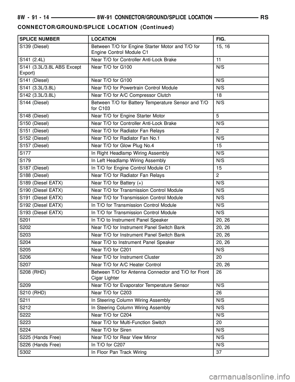
SPLICE NUMBER LOCATION FIG.
S139 (Diesel) Between T/O for Engine Starter Motor and T/O for
Engine Control Module C115, 16
S141 (2.4L) Near T/O for Controller Anti-Lock Brake 11
S141 (3.3L/3.8L ABS Except
Export)Near T/O for G100 N/S
S141 (Diesel) Near T/O for G100 N/S
S141 (3.3L/3.8L) Near T/O for Powertrain Control Module N/S
S142 (3.3L/3.8L) Near T/O for A/C Compressor Clutch 18
S144 (Diesel) Between T/O for Battery Temperature Sensor and T/O
for C103N/S
S148 (Diesel) Near T/O for Engine Starter Motor 5
S150 (Diesel) Near T/O for Controller Anti-Lock Brake N/S
S151 (Diesel) Near T/O for Radiator Fan Relays 2
S152 (Diesel) Near T/O for Radiator Fan No.1 N/S
S157 (Diesel) Near T/O for Glow Plug No.4 15
S177 In Right Headlamp Wiring Assembly N/S
S179 In Left Headlamp Wiring Assembly N/S
S187 (Diesel) In T/O for Engine Control Module C1 15
S188 (Diesel) Near T/O for Radiator Fan Relays 2
S189 (Diesel EATX) Near T/O for Battery (+) N/S
S190 (Diesel EATX) Near T/O for Transmission Control Module N/S
S191 (Diesel EATX) Near T/O for Transmission Control Module N/S
S192 (Diesel EATX) In T/O for Transmission Control Module N/S
S193 (Diesel EATX) In T/O for Transmission Control Module N/S
S201 In T/O to Instrument Panel Speaker 20, 26
S202 Near T/O for Instrument Panel Switch Bank 20, 26
S203 Near T/O for Instrument Panel Switch Bank 20, 26
S204 Near T/O to Instrument Panel Speaker 20, 26
S205 Near T/O for C201 N/S
S206 Near T/O for Instrument Cluster 20
S207 Near T/O for A/C Heater Control 20, 26
S208 (RHD) Between T/O for Antenna Connector and T/O for Front
Cigar Lighter26
S209 Near T/O for Evaporator Temperature Sensor N/S
S210 (RHD) Near T/O for C203 26
S211 In Steering Column Wiring Assembly N/S
S212 In Steering Column Wiring Assembly N/S
S222 Near T/O for C204 N/S
S223 Near T/O for Multi-Function Switch 20
S224 Near T/O for Siren N/S
S225 (Hands Free) Near T/O for Rear View Mirror N/S
S226 (Hands Free) In T/O for C207 N/S
S302 In Floor Pan Track Wiring 37
8W - 91 - 14 8W-91 CONNECTOR/GROUND/SPLICE LOCATIONRS
CONNECTOR/GROUND/SPLICE LOCATION (Continued)
Page 1130 of 2339

Fig. 1 HEADLAMP CONNECTORS
RS8W-91 CONNECTOR/GROUND/SPLICE LOCATION8W-91-17
CONNECTOR/GROUND/SPLICE LOCATION (Continued)
Page 1348 of 2339

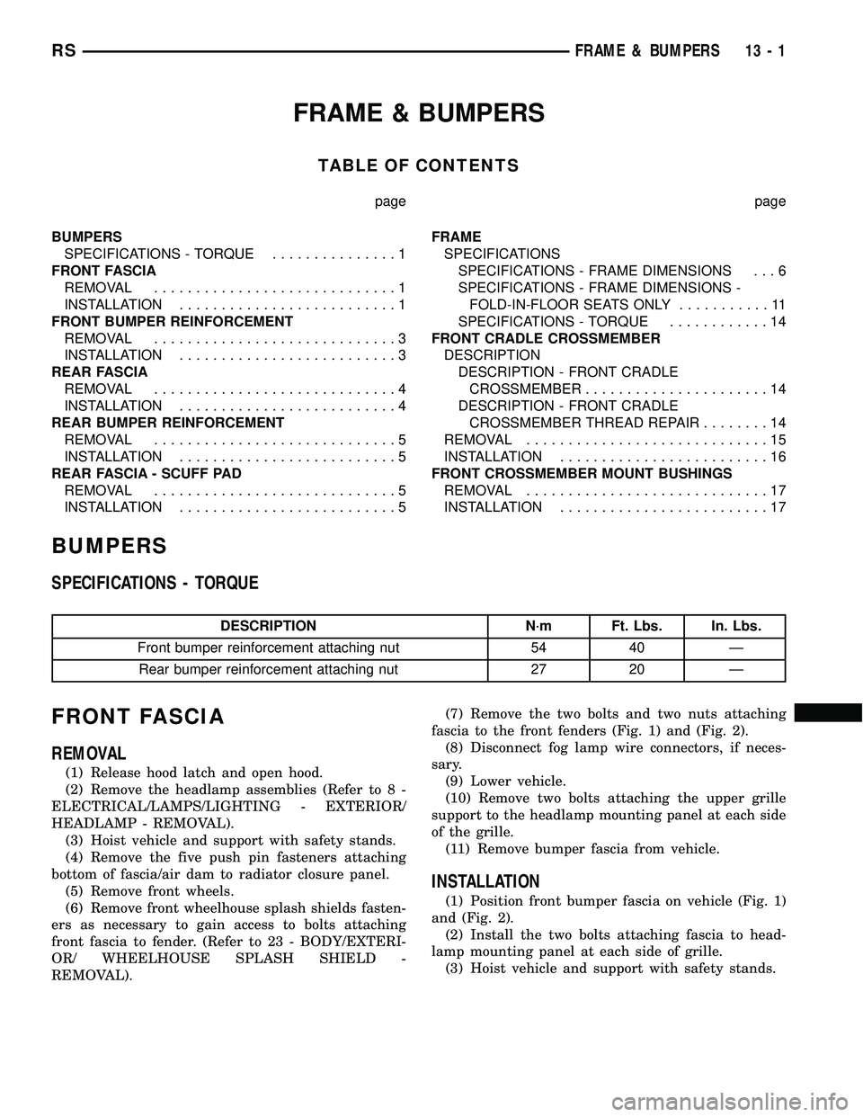
FRAME & BUMPERS
TABLE OF CONTENTS
page page
BUMPERS
SPECIFICATIONS - TORQUE...............1
FRONT FASCIA
REMOVAL.............................1
INSTALLATION..........................1
FRONT BUMPER REINFORCEMENT
REMOVAL.............................3
INSTALLATION..........................3
REAR FASCIA
REMOVAL.............................4
INSTALLATION..........................4
REAR BUMPER REINFORCEMENT
REMOVAL.............................5
INSTALLATION..........................5
REAR FASCIA - SCUFF PAD
REMOVAL.............................5
INSTALLATION..........................5FRAME
SPECIFICATIONS
SPECIFICATIONS - FRAME DIMENSIONS . . . 6
SPECIFICATIONS - FRAME DIMENSIONS -
FOLD-IN-FLOOR SEATS ONLY...........11
SPECIFICATIONS - TORQUE............14
FRONT CRADLE CROSSMEMBER
DESCRIPTION
DESCRIPTION - FRONT CRADLE
CROSSMEMBER......................14
DESCRIPTION - FRONT CRADLE
CROSSMEMBER THREAD REPAIR........14
REMOVAL.............................15
INSTALLATION.........................16
FRONT CROSSMEMBER MOUNT BUSHINGS
REMOVAL.............................17
INSTALLATION.........................17
BUMPERS
SPECIFICATIONS - TORQUE
DESCRIPTION N´m Ft. Lbs. In. Lbs.
Front bumper reinforcement attaching nut 54 40 Ð
Rear bumper reinforcement attaching nut 27 20 Ð
FRONT FASCIA
REMOVAL
(1) Release hood latch and open hood.
(2) Remove the headlamp assemblies (Refer to 8 -
ELECTRICAL/LAMPS/LIGHTING - EXTERIOR/
HEADLAMP - REMOVAL).
(3) Hoist vehicle and support with safety stands.
(4) Remove the five push pin fasteners attaching
bottom of fascia/air dam to radiator closure panel.
(5) Remove front wheels.
(6) Remove front wheelhouse splash shields fasten-
ers as necessary to gain access to bolts attaching
front fascia to fender. (Refer to 23 - BODY/EXTERI-
OR/ WHEELHOUSE SPLASH SHIELD -
REMOVAL).(7) Remove the two bolts and two nuts attaching
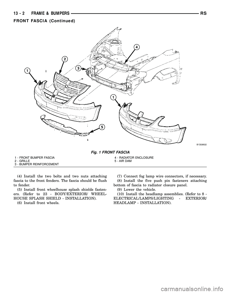
fascia to the front fenders (Fig. 1) and (Fig. 2).
(8) Disconnect fog lamp wire connectors, if neces-
sary.
(9) Lower vehicle.
(10) Remove two bolts attaching the upper grille
support to the headlamp mounting panel at each side
of the grille.
(11) Remove bumper fascia from vehicle.
INSTALLATION
(1) Position front bumper fascia on vehicle (Fig. 1)
and (Fig. 2).
(2) Install the two bolts attaching fascia to head-
lamp mounting panel at each side of grille.
(3) Hoist vehicle and support with safety stands.
RSFRAME & BUMPERS13-1
Page 1349 of 2339

(4) Install the two bolts and two nuts attaching
fascia to the front fenders. The fascia should be flush
to fender.
(5) Install front wheelhouse splash shields fasten-
ers. (Refer to 23 - BODY/EXTERIOR/ WHEEL-
HOUSE SPLASH SHIELD - INSTALLATION).
(6) Install front wheels.(7) Connect fog lamp wire connectors, if necessary.
(8) Install the five push pin fasteners attaching
bottom of fascia to radiator closure panel.
(9) Lower the vehicle.
(10) Install the headlamp assemblies. (Refer to 8 -
ELECTRICAL/LAMPS/LIGHTING - EXTERIOR/
HEADLAMP - INSTALLATION).
Fig. 1 FRONT FASCIA
1 - FRONT BUMPER FASCIA
2 - GRILLE
3 - BUMPER REINFORCEMENT4 - RADIATOR ENCLOSURE
5 - AIR DAM
13 - 2 FRAME & BUMPERSRS
FRONT FASCIA (Continued)
Page 1830 of 2339

(7) Tighten screw to 1.2 N´m (11 in. lbs.) torque.
(8) Install the wiper arms. (Refer to 8 - ELECTRI-
CAL/WIPERS/WASHERS/WIPER ARMS - INSTAL-
LATION)
(9) Check for proper spray pattern from washer
nozzles.
EXTERIOR NAME PLATES -
TAPE ATTACHED
REMOVAL
(1) Mark reference points before removing.
(2) Using a heat gun gently apply heat in a circu-
lar motion to loosen the adhesive bond.
(3) Using a nonmetallic prying device, such as a
plastic or wood trim stick gently pry up at corners
and remove.
(4) Clean off all traces of adhesive or double sided
tape from the panel with a general purpose adhesive
remover.
INSTALLATION
(1) Clean panel surface with isopropy alcohol.
(2) Align badgeing to reference points.
(3) Install and press securely to full adhesive con-
tact
(4) Clean away any reference points.
EXTERIOR NAME PLATES -
ADHESIVE ATTACHED
REMOVAL
(1) Mark reference points before removing.
(2) Using a heat gun gently apply heat in a circu-
lar motion to loosen the adhesive bond.
(3) With your fingernail lift up and peel away
badgeing/tape from panel, using a heat gun as you
go.
(4) Clean off all traces of adhesive from the pan-
el(s) with a general purpose adhesive remover.
INSTALLATION
(1) Clean panel surface with isopropy alcohol.
(2) Remove paper carrier and align badgeing/tape
to reference points or adjacent panel.
(3) Install and press securely, using a plastic
spreader to eliminate all air bubbles.
(4) Remove top protective carrier.
(5) Clean away any reference points.
FRONT FENDER
REMOVAL
(1) Remove headlamp housing. (Refer to 8 - ELEC-
TRICAL/LAMPS/LIGHTING - EXTERIOR/HEAD-
LAMP UNIT - REMOVAL)
(2) Remove mirror bezel
(3) Remove mud guard.
(4) Remove inner splash shield.
(5) Remove fender to fascia nuts.
Fig. 6 COWL COVER
1 - COWL COVER
2 - WIPER PIVOT
3 - WASHER HOSES
4 - HOOD
Fig. 7 COWL COVER RETAINERS
1 - SCREW
2 - WINDSHIELD
3 - COWL COVER
4 - FRONT FENDER
RSEXTERIOR23-51
COWL GRILLE (Continued)
Page 1831 of 2339

(6) Remove outboard cowl grille/fender bracket
screw and antenna right side only.
(7) Remove fender bolt to lower rocker panel.
(8) Remove fender bolt to lower cowl.
(9) Support/remove hood.
(10) Pull fascia away from fender.
(11) Remove bolts attaching fender to upper rail.
(12) Remove fender from vehicle (Fig. 8).
INSTALLATION
(1) Place fender in position on vehicle.
(2) From inside engine compartment, start the
center upper rail bolt. install all the bolts attaching
fender to upper rail and tighten.
(3) Install fender to lower cowl panel bolt.
(4) Install fender to rocker panel bolt.
(5) Place fascia into position.
(6) Install hood/remove support.
(7) Install outboard cowl grille/fender bracket
screw and install antenna right side only.
(8) Install fender to fascia nuts.
(9) Install inner splash shield.
(10) Install mud guard.
(11) Install headlamp assembly. (Refer to 8 -
ELECTRICAL/LAMPS/LIGHTING - EXTERIOR/
HEADLAMP UNIT - INSTALLATION)
(12) Check fender for flush and gap. (Refer to 23 -
BODY/BODY STRUCTURE/GAP AND FLUSH -
SPECIFICATIONS).
FUEL FILL DOOR
REMOVAL
(1) Remove left quarter trim panel.
(2) Remove water shield patch covering access hole
in C-pillar.
(3) Disengage latch release link from clip on fuel
fill blocker latch arm (Fig. 12).
(4) Open fuel fill door.
(5) Remove screws holding fuel fill neck to fuel
filler housing.
(6) Position fuel fill neck out of the way.
(7) Reaching inside fuel filler housing, release clips
holding housing to quarter panel (Fig. 9).
(8) Remove fuel fill door from vehicle.
(9) Disengage clip holding link to fuel fill door
(Fig. 13).
(10) Remove link from fuel fill door.
INSTALLATION
(1) Install spring to housing and door
(2) Snap door into housing.
(3) Insert lockout link into clip on fuel fill door.
(4) Engage clip to hold link to fuel fill door.
(5) Insert lockout link through grommet in panel
between inner and outer quarter panel.
(6) Close fuel fill door.
(7) Install fuel filler housing to outer quarter
panel.
(8) Verify that all clips on fuel filler housing are
fully engaged to outer quarter panel.
(9) Place fuel fill neck in position.
(10) Install screws to hold fuel fill neck to fuel
filler housing.
Fig. 8 FENDER
1 - FASTENERS
2 - FENDER
3 - FASTENERS
Fig. 9 FUEL FILLER HOUSING AND DOOR
1 - FUEL FILLER HOUSING W/LATCH
2 - CLIP
3 - FUEL FILLER HOUSING DOOR
4 - CLIPS
5 - FIX CLIP
23 - 52 EXTERIORRS
FRONT FENDER (Continued)
Page 1856 of 2339

INSTRUMENT PANEL TOP PAD
ASSEMBLY
REMOVAL
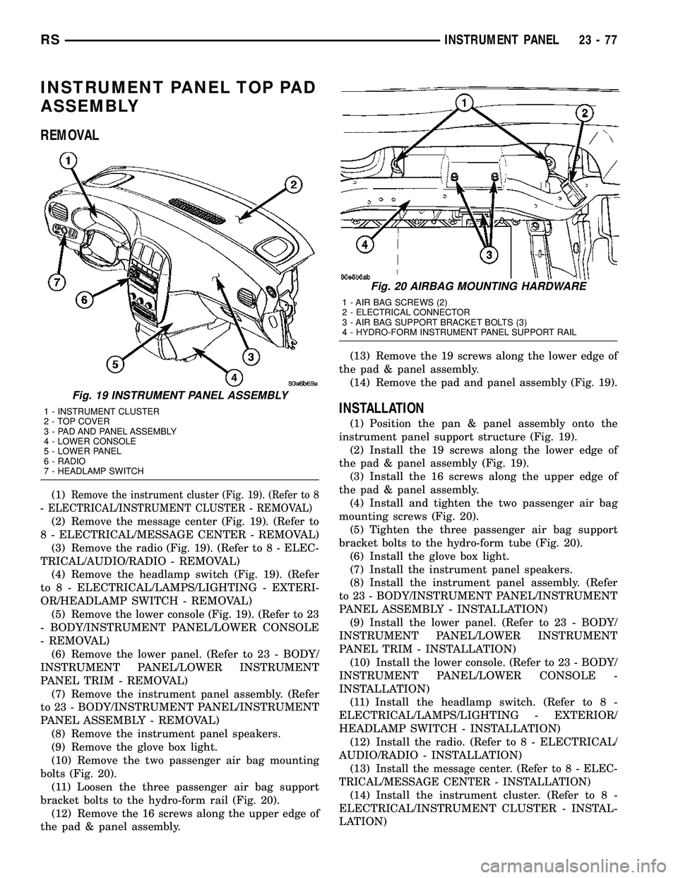
(1)Remove the instrument cluster (Fig. 19). (Refer to 8
- ELECTRICAL/INSTRUMENT CLUSTER - REMOVAL)
(2) Remove the message center (Fig. 19). (Refer to
8 - ELECTRICAL/MESSAGE CENTER - REMOVAL)
(3) Remove the radio (Fig. 19). (Refer to 8 - ELEC-
TRICAL/AUDIO/RADIO - REMOVAL)
(4) Remove the headlamp switch (Fig. 19). (Refer
to 8 - ELECTRICAL/LAMPS/LIGHTING - EXTERI-
OR/HEADLAMP SWITCH - REMOVAL)
(5) Remove the lower console (Fig. 19). (Refer to 23
- BODY/INSTRUMENT PANEL/LOWER CONSOLE
- REMOVAL)
(6) Remove the lower panel. (Refer to 23 - BODY/
INSTRUMENT PANEL/LOWER INSTRUMENT
PANEL TRIM - REMOVAL)
(7) Remove the instrument panel assembly. (Refer
to 23 - BODY/INSTRUMENT PANEL/INSTRUMENT
PANEL ASSEMBLY - REMOVAL)
(8) Remove the instrument panel speakers.
(9) Remove the glove box light.
(10) Remove the two passenger air bag mounting
bolts (Fig. 20).
(11) Loosen the three passenger air bag support
bracket bolts to the hydro-form rail (Fig. 20).
(12) Remove the 16 screws along the upper edge of
the pad & panel assembly.(13) Remove the 19 screws along the lower edge of
the pad & panel assembly.
(14) Remove the pad and panel assembly (Fig. 19).
INSTALLATION
(1) Position the pan & panel assembly onto the
instrument panel support structure (Fig. 19).
(2) Install the 19 screws along the lower edge of
the pad & panel assembly (Fig. 19).
(3) Install the 16 screws along the upper edge of
the pad & panel assembly.
(4) Install and tighten the two passenger air bag
mounting screws (Fig. 20).
(5) Tighten the three passenger air bag support
bracket bolts to the hydro-form tube (Fig. 20).
(6) Install the glove box light.
(7) Install the instrument panel speakers.
(8) Install the instrument panel assembly. (Refer
to 23 - BODY/INSTRUMENT PANEL/INSTRUMENT
PANEL ASSEMBLY - INSTALLATION)
(9) Install the lower panel. (Refer to 23 - BODY/
INSTRUMENT PANEL/LOWER INSTRUMENT
PANEL TRIM - INSTALLATION)
(10) Install the lower console. (Refer to 23 - BODY/
INSTRUMENT PANEL/LOWER CONSOLE -
INSTALLATION)
(11) Install the headlamp switch. (Refer to 8 -
ELECTRICAL/LAMPS/LIGHTING - EXTERIOR/
HEADLAMP SWITCH - INSTALLATION)
(12) Install the radio. (Refer to 8 - ELECTRICAL/
AUDIO/RADIO - INSTALLATION)
(13)
Install the message center. (Refer to 8 - ELEC-
TRICAL/MESSAGE CENTER - INSTALLATION)
(14) Install the instrument cluster. (Refer to 8 -
ELECTRICAL/INSTRUMENT CLUSTER - INSTAL-
LATION)
Fig. 19 INSTRUMENT PANEL ASSEMBLY
1 - INSTRUMENT CLUSTER
2 - TOP COVER
3 - PAD AND PANEL ASSEMBLY
4 - LOWER CONSOLE
5 - LOWER PANEL
6 - RADIO
7 - HEADLAMP SWITCH
Fig. 20 AIRBAG MOUNTING HARDWARE
1 - AIR BAG SCREWS (2)
2 - ELECTRICAL CONNECTOR
3 - AIR BAG SUPPORT BRACKET BOLTS (3)
4 - HYDRO-FORM INSTRUMENT PANEL SUPPORT RAIL
RSINSTRUMENT PANEL23-77
Page 1958 of 2339

SPECIFICATIONS
ITEM LOCATION GAP FLUSH
A HOOD TO FASCIA (VOYAGER ONLY)
8.0 2.0
PARALLEL WITHIN 2.0 RIGHT TO
LEFT2.5 OVER FLUSH TO HOOD
1.5 CONSISTENT WITHIN 2.0
B HEADLAMP MODULE TO
HOOD8.0 2.0
PARALLEL WITHIN 2.0 RIGHT TO
LEFT
C HOOD TO FENDER (FORE &
AFT)0.0 1.5
LEFT TO RIGHT WITHIN 1.5
D HOOD TO FENDER 4.0 1.5
PARALLEL WITHIN 2.5 AND
WITHIN 1.5 LEFT TO RIGHTUNDER FLUSH 2.0
E FENDER TO DOOR 5.0 1.5
PARALLEL WITHIN 2.0UNDER FLUSH 0.5 1.5
CONSISTENT WITHIN 2.0
F FRONT DOOR TO9A9PILLAR
COVERUNDER FLUSH 0.5 2.0
G9A9PILLAR COVER TO
SLIDING DOOR5.0 2.0
PARALLEL WITHIN 1.01.0 UNDER FLUSH 2.0
CONSISTENT WITHIN 1.0
H FRONT DOOR APPLIQUE TO
SLIDING DOOR GLASS5.0 2.0
PARALLEL WITHIN 2.01.0 OVER FLUSH 2.0
CONSISTENT WITHIN 3.0
I FRONT DOOR TO SLIDING
DOOR5.0 2.0
PARALLEL WITHIN 2.0 2.0 CONSISTENT WITHIN
2.0
J SLIDING DOOR TO REAR
APERTURE GLASS5.0 2.0
PARALLEL WITHIN 1.5 3.0 CONSISTENT WITHIN
3.0
K SLIDING DOOR TO REAR
APERTURE5.0 1.5
PARALLEL WITHIN 2.0 1.5 CONSISTENT WITHIN
1.5
L TAIL LAMP TO BODY SIDE
APERTURE1.0 1.0
PARALLEL WITHIN 1.5OVER FLUSH
M TAIL LAMP TO LIFTGATE 4.0 2.0 OVER FLUSH
N LIFTGATE TO BODY SIDE
APERTURE4.0 1.5 UNDER FLUSH 1.0 2.5
CONSISTENT WITHIN 2.0
O LIFTGATE TO ROOF 8.0 2.0 UNDER FLUSH 1.5
P LIFTGATE TO FASCIA 8.0 2.5
PARALLEL WITHIN 3.0OVER FLUSH
Q LIFTGATE TO REAR FASCIA 2.0 0.5 UNDER FLUSH TO 1.0
MAXIMUM
R FUEL FILLER DOOR TO BODY
SIDE APERTUREUNDER FLUSH 0.5 1.0
NOTE: All measurements are in mm.
RSBODY STRUCTURE23 - 179
GAP AND FLUSH (Continued)
Page 2013 of 2339

WELD LOCATIONS
SPECIFICATIONS
SPECIFICATIONS - WELD LOCATIONS
INDEX
DESCRIPTION FIGURE
FRONT FENDER SHIELD - RIGHT 85
FRONT FENDER SHIELD - LEFT 86
STRUT TOWER AND REINFORCEMENTS - RIGHT 87
SUSPENSION RETAINERS AND REINFORCEMENTS - RIGHT 88
STRUT TOWER AND REINFORCEMENTS - LEFT 89
SUSPENSION RETAINERS AND REINFORCEMENTS - LEFT 90
FLOOR PAN REINFORCEMENTS - SIDE RAILS 91
REAR SUSPENSION BRACKETS 92
FLOOR PAN CROSS MEMBERS 93
SEAT REINFORCEMENTS - LONG WHEEL BASE ONLY 94
STRIKER REINFORCEMENTS - LONG WHEEL BASE ONLY 95
FUEL TANK MOUNTING/REAR SEAT AND SUSPENSION 96
REAR SUSPENSION HANGER BRACKETS - LONG WHEEL BASE 97
FRONT SEAT CROSS MEMBER 98
FLOOR PAN SIDE RAIL REINFORCEMENT 99
SILL BULKHEAD REINFORCEMENTS 100
FLOOR PAN CROSS MEMBER REINFORCEMENTS 101
FRONT SEAT CROSS MEMBER 102
SEAT REINFORCEMENT CROSS MEMBERS - SHORT WHEEL BASE 103
CENTER CONSOLE REINFORCEMENT - SHORT WHEEL BASE 104
REAR SUSPENSION HANGER BRACKETS - SHORT WHEEL BASE 105
LOWER LIFTGATE PANEL LATCH REINFORCEMENT 106
ENGINE MOUNTING PLATE AND TOW BRACKET 107
HEADLAMP MOUNTING PLATE 108
LOWER RADIATOR CROSS MEMBER BRACKETS 109
CROSS MEMBER EXTENSIONS 110
JACK MOUNTING BRACKET - LONG WHEEL BASE SHOWN, SHORT SIMILAR 111
FRONT SEAT CROSS MEMBER - LONG WHEELBASE ONLY 112
FRONT SEAT CROSS MEMBER - ALL WHEEL DRIVE ONLY 113
FUEL TANK SUPPORT CROSS MEMBERS - LONG WHEEL BASE ONLY 114
REAR SUPPORT AND TIRE STOWAGE CROSS MEMBERS - LONG WHEEL BASE
ONLY11 5
INNER SIDE SILLS - LONG WHEEL BASE ONLY 116
WHEELHOUSES, SIDE SILLS, SUSPENSION BRACKETS - LONG WHEEL BASE ONLY 117
REAR SEAT REINFORCEMENTS - SHORT WHEEL BASE ONLY 118
23 - 234 BODY STRUCTURERS
Page 2039 of 2339

Fig. 108 HEADLAMP MOUNTING PLATE
23 - 260 BODY STRUCTURERS
WELD LOCATIONS (Continued)