location CHRYSLER CARAVAN 2005 Workshop Manual
[x] Cancel search | Manufacturer: CHRYSLER, Model Year: 2005, Model line: CARAVAN, Model: CHRYSLER CARAVAN 2005Pages: 2339, PDF Size: 59.69 MB
Page 339 of 2339
(2) Perform Starter Solenoid test BEFORE per-
forming the starter relay test.
(3) Perform a visual inspection of the starter/
starter solenoid for corrosion, loose connections or
faulty wiring.
(4) Locate and remove the starter relay from the
Power Distribution Center (PDC). Refer to the PDC
label for relay identification and location.
(5) Connect a remote starter switch or a jumper
wire between the remote battery positive post and
terminal 87 of the starter relay connector.
(a) If engine cranks, starter/starter solenoid is
good. Go to the Starter Relay Test.
(b) If engine does not crank or solenoid chatters,
check wiring and connectors from starter relay to
starter solenoid and from the battery positive ter-
minal to starter post for loose or corroded connec-
tions. Particularly at starter terminals.
(c) Repeat test. If engine still fails to crank prop-
erly, trouble is within starter or starter mounted
solenoid, and replace starter. Inspect the ring gear
teeth.
STARTER RELAY
WARNING: CHECK TO ENSURE THAT THE TRANS-
MISSION IS IN THE PARK/NEUTRAL POSITION
WITH THE PARKING BRAKE APPLIED. THIS MAY
RESULT IN PERSONAL INJURY OR DEATH.
RELAY TEST
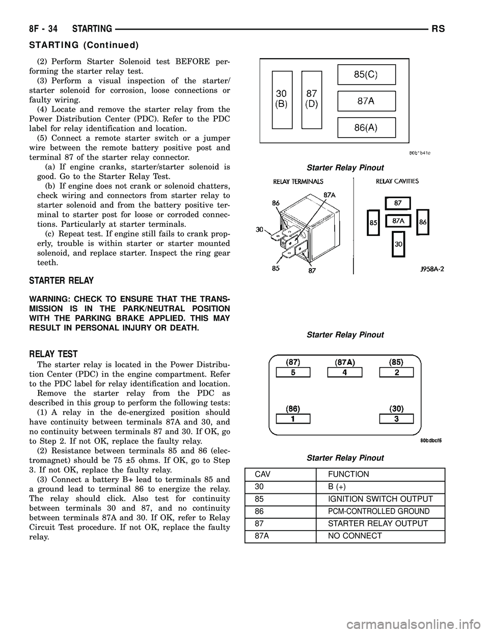
The starter relay is located in the Power Distribu-
tion Center (PDC) in the engine compartment. Refer
to the PDC label for relay identification and location.
Remove the starter relay from the PDC as
described in this group to perform the following tests:
(1) A relay in the de-energized position should
have continuity between terminals 87A and 30, and
no continuity between terminals 87 and 30. If OK, go
to Step 2. If not OK, replace the faulty relay.
(2) Resistance between terminals 85 and 86 (elec-
tromagnet) should be 75 5 ohms. If OK, go to Step
3. If not OK, replace the faulty relay.
(3) Connect a battery B+ lead to terminals 85 and
a ground lead to terminal 86 to energize the relay.
The relay should click. Also test for continuity
between terminals 30 and 87, and no continuity
between terminals 87A and 30. If OK, refer to Relay
Circuit Test procedure. If not OK, replace the faulty
relay.
CAV FUNCTION
30 B (+)
85 IGNITION SWITCH OUTPUT
86
PCM-CONTROLLED GROUND
87 STARTER RELAY OUTPUT
87A NO CONNECT
Starter Relay Pinout
Starter Relay Pinout
Starter Relay Pinout
8F - 34 STARTINGRS
STARTING (Continued)
Page 340 of 2339
RELAY CIRCUIT TEST
(1) The relay common feed terminal cavity (30) is
connected to battery voltage and should be hot at all
times. If OK, go to Step 2. If not OK, repair the open
circuit to the PDC fuse as required.
(2) The relay normally closed terminal (87A) is
connected to terminal 30 in the de-energized position,
but is not used for this application. Go to Step 3.
(3) The relay normally open terminal (87) is con-
nected to the common feed terminal (30) in the ener-
gized position. This terminal supplies battery voltage
to the starter solenoid field coils. There should be
continuity between the cavity for relay terminal 87
and the starter solenoid terminal at all times. If OK,
go to Step 4. If not OK, repair the open circuit to the
starter solenoid as required.
(4) The coil battery terminal (85) is connected to
the electromagnet in the relay. It is energized when
the ignition switch is held in the Start position and
the clutch pedal is depressed (manual trans). Check
for battery voltage at the cavity for relay terminal 86
with the ignition switch in the Start position and the
clutch pedal is depressed (manual trans), and no
voltage when the ignition switch is released to the
On position. If OK, go to Step 5. If not OK, check for
an open or short circuit to the ignition switch and
repair, if required. If the circuit to the ignition switch
is OK, see the Ignition Switch Test procedure in this
group.
(5) The coil ground terminal (86) is connected to
the electromagnet in the relay. It is grounded by the
PCM if the conditions are right to start the car. For
automatic trans. cars the PCM must see Park Neu-
tral switch low and near zero engine speed (rpm).
For manual trans. cars the PCM only needs to see
near zero engine speed (rpm) and low clutch inter-
lock input and see near zero engine speed (rpm). To
diagnose the Park Neutral switch of the trans range
sensor refer to the transaxle section. Check for conti-
nuity to ground while the ignition switch is in the
start position and if equipped the clutch pedal
depressed. If not OK and the vehicle has an auto-
matic trans. verify Park Neutral switch operation. If
that checks OK check for continuity between PCM
and the terminal 86. Repair open circuit as required.
Also check the clutch interlock switch operation if
equipped with a manual transmission. If OK, the
PCM may be defective.
SAFETY SWITCHES
For diagnostics of the Transmission Range Sensor,
refer to the Transaxle section for more information.
If equipped with Clutch Interlock/Upstop Switch,
refer to Diagnosis and Testing in the Clutch section.
IGNITION SWITCH
After testing starter solenoid and relay, test igni-
tion switch and wiring. Refer to the Ignition Section
or Wiring Diagrams for more information. Check all
wiring for opens or shorts, and all connectors for
being loose or corroded.
BATTERY
For battery diagnosis and testing, refer to the Bat-
tery section for procedures.
ALL RELATED WIRING AND CONNECTORS
Refer to Wiring Diagrams for more information.
DIAGNOSIS AND TESTING - FEED CIRCUIT
RESISTANCE TEST
Before proceeding with this operation, review Diag-
nostic Preparation and Starter Feed Circuit Tests.
The following operation will require a voltmeter,
accurate to 1/10 of a volt.
CAUTION: Ignition and Fuel systems must be dis-
abled to prevent engine start while performing the
following tests.
(1) To disable the Ignition and Fuel systems, dis-
connect the Automatic Shutdown Relay (ASD). The
ASD relay is located in the Power Distribution Cen-
ter (PDC). Refer to the PDC cover for proper relay
location.
(2) Gain access to battery terminals.
(3) With all wiring harnesses and components
properly connected, perform the following:
(a) Connect the negative lead of the voltmeter to
the battery negative post, and positive lead to the
battery negative cable clamp. Rotate and hold the
ignition switch in the START position. Observe the
voltmeter. If voltage is detected, correct poor con-
tact between cable clamp and post.
(b) Connect positive lead of the voltmeter to the
battery positive post, and negative lead to the bat-
tery positive cable clamp. Rotate and hold the igni-
tion switch key in the START position. Observe the
voltmeter. If voltage is detected, correct poor con-
tact between the cable clamp and post.
(c) Connect negative lead of voltmeter to battery
negative terminal, and positive lead to engine
block near the battery cable attaching point.
Rotate and hold the ignition switch in the START
position. If voltage reads above 0.2 volt, correct
poor contact at ground cable attaching point. If
voltage reading is still above 0.2 volt after correct-
ing poor contacts, replace ground cable.
(4) Connect positive voltmeter lead to the starter
motor housing and the negative lead to the battery
negative terminal. Hold the ignition switch key in
RSSTARTING8F-35
STARTING (Continued)
Page 341 of 2339

the START position. If voltage reads above 0.2 volt,
correct poor starter to engine ground.
(a) Connect the positive voltmeter lead to the
battery positive terminal, and negative lead to bat-
tery cable terminal on starter solenoid. Rotate and
hold the ignition switch in the START position. If
voltage reads above 0.2 volt, correct poor contact at
battery cable to solenoid connection. If reading is
still above 0.2 volt after correcting poor contacts,
replace battery positive cable.
(b) If resistance tests do not detect feed circuit
failures, replace the starter motor.
DIAGNOSIS AND TESTING - FEED CIRCUIT
TEST
NOTE: The following results are based upon the
vehicle being at room temperature.
The following procedure will require a suitable
volt-ampere tester (Fig. 1).
CAUTION: Before performing any starter tests, the
ignition and fuel systems must be disabled.(1) Check battery before performing this test. Bat-
tery must be fully charged.
(2) Connect a volt-ampere tester to the battery ter-
minals. Refer to the operating instructions provided
with the tester being used.
(3) To disable the ignition and fuel systems, dis-
connect the Automatic Shutdown Relay (ASD). The
ASD relay is located in the Power Distribution Cen-
ter (PDC). Refer to the PDC cover for proper relay
location.
(4) Verify that all lights and accessories are OFF,
and the transmission shift selector is in the PARK
and SET parking brake.
CAUTION: Do not overheat the starter motor or
draw the battery voltage below 9.6 volts during
cranking operations.
(5) Rotate and hold the ignition switch in the
START position. Observe the volt-ampere tester (Fig.
1).
²If voltage reads above 9.6 volts, and amperage
draw reads above 280 amps, check for engine seizing
or faulty starter.
²If voltage reads 12.4 volts or greater and amper-
age reads 0 to 10 amps, check for corroded cables
and/or bad connections.
²Voltage below 9.6 volts and amperage draw
above 300 amps, the problem is the starter. Replace
the starter refer to starter removal.
(6) After the starting system problems have been
corrected, verify the battery state-of-charge and
charge battery if necessary. Disconnect all testing
equipment and connect ASD relay. Start the vehicle
several times to assure the problem has been cor-
rected.
SPECIFICATIONS
Torques
DESCRIPTION N´m Ft. Lbs. In. Lbs.
Starter Mounting Bolts 47.4 35
Starter Solenoid Battery
Nut11.3 8.3 100
Fig. 1 Volt Ampere Tester
8F - 36 STARTINGRS
STARTING (Continued)
Page 343 of 2339

(8) Remove starter.
REMOVAL - 3.3/3.8L
(1) Release hood latch and open hood.
(2) Disconnect and isolate the battery negative
cable.
(3) Hoist and support vehicle on safety stands.
(4) Remove nut holding B+ terminal to starter
solenoid (Fig. 5).
(5) Disconnect solenoid connector from starter.
(6) Remove bolts holding starter to transaxle bell-
housing (Fig. 6).(7) Remove starter from bellhousing (Fig. 7).
(8) Separate starter spacer from transaxle bell-
housing.
REMOVAL - 2.5L
(1) Disconnect the negative battery cable.
(2) Raise vehicle and support.
(3) Remove the lower engine splash shield.
(4) Remove the electrical connectors from the
starter (Fig. 8).Fig. 5 Starter
1 - SOLENOID CONNECTOR
2 - B+ CONNECTOR
Fig. 6 Starter Bolts
1-STARTER
2 - STARTER BOLTS
3 - TRANSAXLE
4 - ENGINE MOUNT
Fig. 7 STARTER 3.3/3.8L
1 - BELL HOUSING PLATE
2 - FLYWHEEL
3 - ENGINE MOUNT
4-STARTER
5 - SPACER
Fig. 8 STARTER LOCATION
8F - 38 STARTINGRS
STARTER MOTOR (Continued)
Page 348 of 2339
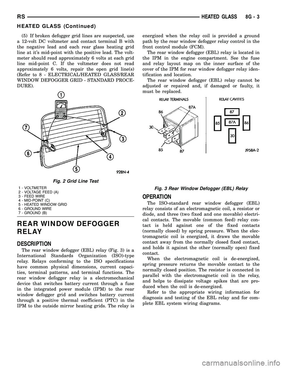
(5) If broken defogger grid lines are suspected, use
a 12-volt DC voltmeter and contact terminal B with
the negative lead and each rear glass heating grid
line at it's mid-point with the positive lead. The volt-
meter should read approximately 6 volts at each grid
line mid-point C. If the voltmeter does not read
approximately 6 volts, repair the open grid line(s)
(Refer to 8 - ELECTRICAL/HEATED GLASS/REAR
WINDOW DEFOGGER GRID - STANDARD PROCE-
DURE).
REAR WINDOW DEFOGGER
RELAY
DESCRIPTION
The rear window defogger (EBL) relay (Fig. 3) is a
International Standards Organization (ISO)-type
relay. Relays conforming to the ISO specifications
have common physical dimensions, current capaci-
ties, terminal patterns, and terminal functions. The
rear window defogger relay is a electromechanical
device that switches battery current through a fuse
in the integrated power module (IPM) to the rear
window defogger grid and switches battery current
through a positive thermal coefficient (PTC) in the
IPM to the outside mirror heating grids. The relay isenergized when the relay coil is provided a ground
path by the rear window defogger relay control in the
front control module (FCM).
The rear window defogger (EBL) relay is located in
the IPM in the engine compartment. See the fuse
and relay layout map on the inner surface of the
cover of the IPM for rear window defogger relay iden-
tification and location.
The rear window defogger (EBL) relay cannot be
adjusted or repaired and, if damaged or faulty, it
must be replaced.
OPERATION
The ISO-standard rear window defogger (EBL)
relay consists of an electromagnetic coil, a resistor or
diode, and three (two fixed and one movable) electri-
cal contacts. The movable (common feed) relay con-
tact is held against one of the fixed contacts
(normally closed) by spring pressure. When the elec-
tromagnetic coil is energized, it draws the movable
contact away from the normally closed fixed contact,
and holds it against the other (normally open) fixed
contact.
When the electromagnetic coil is de-energized,
spring pressure returns the movable contact to the
normally closed position. The resistor is connected in
parallel with the electromagnetic coil in the relay,
and helps to dissipate voltage spikes that are pro-
duced when the coil is de-energized.
Refer to the appropriate wiring information for
diagnosis and testing of the EBL relay and for com-
plete EBL system wiring diagrams.
Fig. 2 Grid Line Test
1 - VOLTMETER
2 - VOLTAGE FEED (A)
3 - FEED WIRE
4 - MID-POINT (C)
5 - HEATED WINDOW GRID
6 - GROUND WIRE
7 - GROUND (B)Fig. 3 Rear Window Defogger (EBL) Relay
RSHEATED GLASS8G-3
HEATED GLASS (Continued)
Page 349 of 2339
REMOVAL
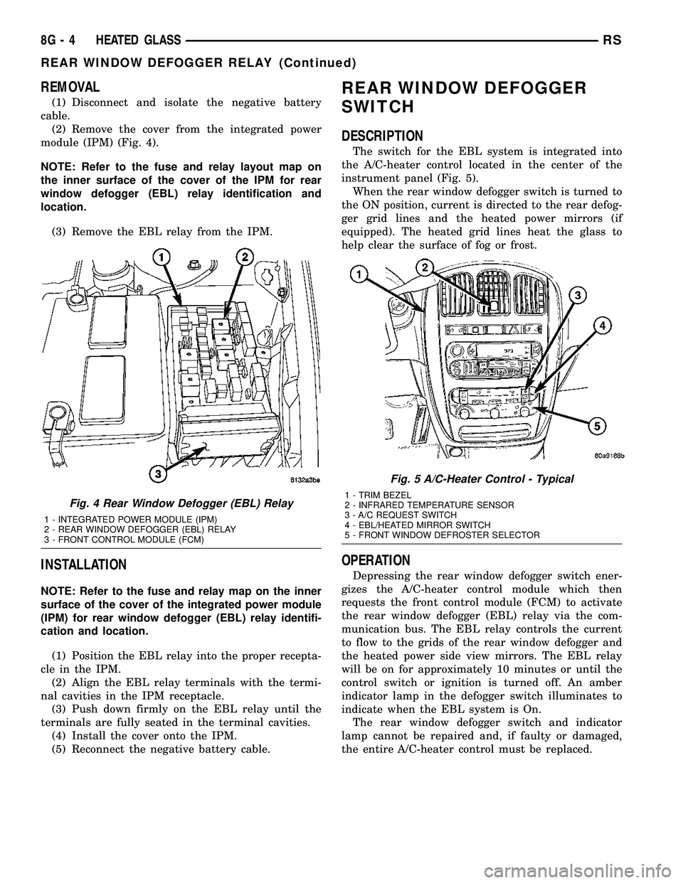
(1) Disconnect and isolate the negative battery
cable.
(2) Remove the cover from the integrated power
module (IPM) (Fig. 4).
NOTE: Refer to the fuse and relay layout map on
the inner surface of the cover of the IPM for rear
window defogger (EBL) relay identification and
location.
(3) Remove the EBL relay from the IPM.
INSTALLATION
NOTE: Refer to the fuse and relay map on the inner
surface of the cover of the integrated power module
(IPM) for rear window defogger (EBL) relay identifi-
cation and location.
(1) Position the EBL relay into the proper recepta-
cle in the IPM.
(2) Align the EBL relay terminals with the termi-
nal cavities in the IPM receptacle.
(3) Push down firmly on the EBL relay until the
terminals are fully seated in the terminal cavities.
(4) Install the cover onto the IPM.
(5) Reconnect the negative battery cable.
REAR WINDOW DEFOGGER
SWITCH
DESCRIPTION
The switch for the EBL system is integrated into
the A/C-heater control located in the center of the
instrument panel (Fig. 5).
When the rear window defogger switch is turned to
the ON position, current is directed to the rear defog-
ger grid lines and the heated power mirrors (if
equipped). The heated grid lines heat the glass to
help clear the surface of fog or frost.
OPERATION
Depressing the rear window defogger switch ener-
gizes the A/C-heater control module which then
requests the front control module (FCM) to activate
the rear window defogger (EBL) relay via the com-
munication bus. The EBL relay controls the current
to flow to the grids of the rear window defogger and
the heated power side view mirrors. The EBL relay
will be on for approximately 10 minutes or until the
control switch or ignition is turned off. An amber
indicator lamp in the defogger switch illuminates to
indicate when the EBL system is On.
The rear window defogger switch and indicator
lamp cannot be repaired and, if faulty or damaged,
the entire A/C-heater control must be replaced.
Fig. 4 Rear Window Defogger (EBL) Relay
1 - INTEGRATED POWER MODULE (IPM)
2 - REAR WINDOW DEFOGGER (EBL) RELAY
3 - FRONT CONTROL MODULE (FCM)
Fig. 5 A/C-Heater Control - Typical
1 - TRIM BEZEL
2 - INFRARED TEMPERATURE SENSOR
3 - A/C REQUEST SWITCH
4 - EBL/HEATED MIRROR SWITCH
5 - FRONT WINDOW DEFROSTER SELECTOR
8G - 4 HEATED GLASSRS
REAR WINDOW DEFOGGER RELAY (Continued)
Page 350 of 2339

REAR WINDOW DEFOGGER
GRID
STANDARD PROCEDURE
GRID REPAIR PROCEDURE
WARNING: Materials contained in the Repair Kit
(Part Number 04549275) may cause skin or eye irri-
tation. The kit contains epoxy resin and amine type
hardener, which are harmful if swallowed. Avoid
contact with the skin and eyes. For skin contact,
wash the affected areas with soap and water. For
contact with the eyes, flush with plenty of water. Do
not take internally. If taken internally, induce vomit-
ing and call a physician immediately. Use with ade-
quate ventilation. Do not use near fire or flame.
Contains flammable solvents. Keep out of the reach
of children. Failure to follow the warnings could
result in possible personal injury or death.
Repair of the rear glass heating grid lines, bus
bars or terminals can be accomplished using the
MopartRear Window Defogger Repair Kit (Part
Number 04549275) or equivalent.
(1) Mask the repair area with masking tape so
that the conductive epoxy can be applied neatly (Fig.
6). Extend the epoxy application onto the grid line or
the bus bar on each side of the break.
(2) Follow the instructions in the repair kit for
preparing the damaged area.
(3) Remove the package separator clamp and mix
the two conductive epoxy components thoroughly
within the packaging. Fold the package in half and
cut the center corner to dispense the epoxy.
(4) For grid line repairs, mask the area to be
repaired with masking tape or use a template.
(5) Apply the epoxy through the slit in the mask-
ing tape or template. Overlap both ends of the break
by at least 19 millimeters (0.75 inch).
(6) For a terminal replacement, mask the adjacent
areas so the epoxy can be extended onto the adjacent
grid line as well as the bus bar. Apply a thin layer of
epoxy to the area where the terminal was fastened
and onto the adjacent grid line.(7) Apply a thin layer of conductive epoxy to the
terminal and place it in the proper location on the
bus bar. To prevent the terminal from moving while
the epoxy is curing, it must be wedged or clamped.
(8) Carefully remove the masking tape or tem-
plate.
CAUTION: Do not allow the glass surface to exceed
204É C (400É F) when using a heat gun, or the glass
may fracture.
(9) Allow the epoxy to cure 24 hours at room tem-
perature, or carefully use a heat gun for fifteen min-
utes. When using a heat gun, hold it approximately
25.4 centimeters (10 inches) from the repair and do
not allow the glass surface to exceed 204É C (400É F).
NOTE: Do not attach the wire harness connectors
to the terminals until the curing process is com-
plete.
(10) After the conductive epoxy is properly cured,
remove the wedge or clamp from the terminal.
(11) Connect the wire harness leads to the grid
terminals and verify EBL operation.
Fig. 6 Grid Line Repair
1 - BREAK
2 - GRID LINE
3 - MASKING TAPE
RSHEATED GLASS8G-5
Page 352 of 2339
HEATED SEAT SYSTEM
TABLE OF CONTENTS
page page
HEATED SEAT SYSTEM
DESCRIPTION..........................7
OPERATION............................8
DIAGNOSIS AND TESTING
HEATED SEAT SYSTEM.................8
HEATED SEAT SWITCH
DESCRIPTION..........................8
OPERATION............................9
DIAGNOSIS AND TESTING
DRIVER HEATED SEAT SWITCH..........9
REMOVAL.............................10
INSTALLATION.........................10HEATED SEAT ELEMENTS
DESCRIPTION.........................11
OPERATION...........................11
DIAGNOSIS AND TESTING
HEATED SEAT ELEMENTS..............11
REMOVAL.............................12
INSTALLATION.........................12
HEATED SEAT SENSOR
DESCRIPTION.........................13
OPERATION...........................13
DIAGNOSIS AND TESTING
HEATED SEAT SENSOR................13
HEATED SEAT SYSTEM
DESCRIPTION
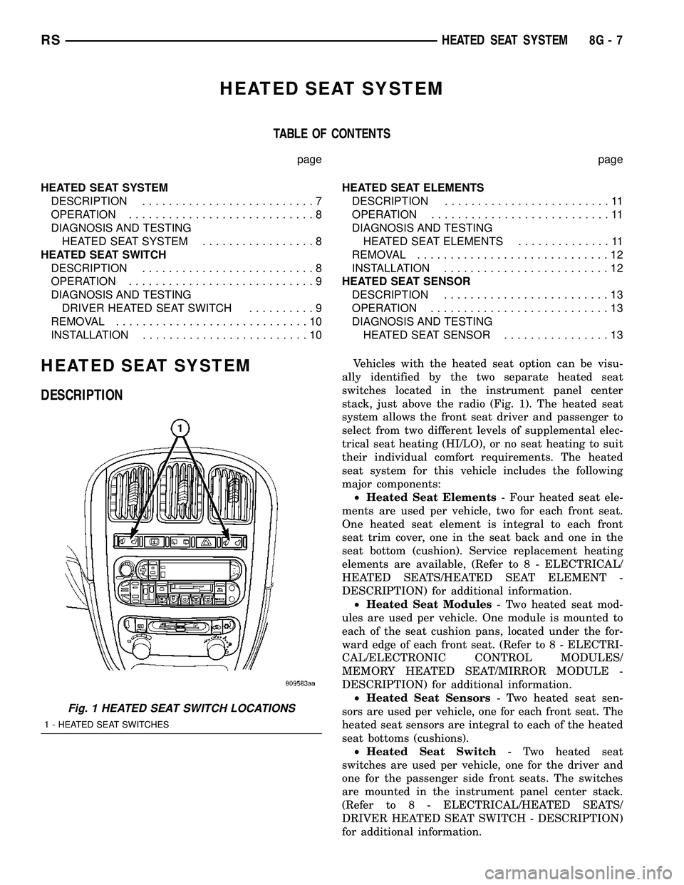
Vehicles with the heated seat option can be visu-
ally identified by the two separate heated seat
switches located in the instrument panel center
stack, just above the radio (Fig. 1). The heated seat
system allows the front seat driver and passenger to
select from two different levels of supplemental elec-
trical seat heating (HI/LO), or no seat heating to suit
their individual comfort requirements. The heated
seat system for this vehicle includes the following
major components:
²Heated Seat Elements- Four heated seat ele-
ments are used per vehicle, two for each front seat.
One heated seat element is integral to each front
seat trim cover, one in the seat back and one in the
seat bottom (cushion). Service replacement heating
elements are available, (Refer to 8 - ELECTRICAL/
HEATED SEATS/HEATED SEAT ELEMENT -
DESCRIPTION) for additional information.
²Heated Seat Modules- Two heated seat mod-
ules are used per vehicle. One module is mounted to
each of the seat cushion pans, located under the for-
ward edge of each front seat. (Refer to 8 - ELECTRI-
CAL/ELECTRONIC CONTROL MODULES/
MEMORY HEATED SEAT/MIRROR MODULE -
DESCRIPTION) for additional information.
²Heated Seat Sensors- Two heated seat sen-
sors are used per vehicle, one for each front seat. The
heated seat sensors are integral to each of the heated
seat bottoms (cushions).
²Heated Seat Switch- Two heated seat
switches are used per vehicle, one for the driver and
one for the passenger side front seats. The switches
are mounted in the instrument panel center stack.
(Refer to 8 - ELECTRICAL/HEATED SEATS/
DRIVER HEATED SEAT SWITCH - DESCRIPTION)
for additional information.
Fig. 1 HEATED SEAT SWITCH LOCATIONS
1 - HEATED SEAT SWITCHES
RSHEATED SEAT SYSTEM8G-7
Page 353 of 2339
Hard wired circuitry connects the heated seat sys-
tem components to each other through the electrical
system of the vehicle. These circuits may be con-
nected to each other, to the vehicle electrical system
and to the heated seat system components through
the use of a combination of soldered splices and
splice block connectors. Refer to the appropriate wir-
ing information for complete circuit schematic or con-
nector pin-out information.
OPERATION
The heated seat system components operate on
battery current received through a fuse in the Inte-
grated Power Module (IPM) on a fused ignition
switch output (run) circuit from the Body Control
Module (BCM). The system will only operate when
the ignition switch is in the On position. The heated
seat system will be turned Off automatically when-
ever the ignition switch is turned to any position
except On. Also, the heated seat system will not oper-
ate when the surface temperature of the seat cushion
cover at either heated seat sensor is above the
designed temperature set points of the system.
DIAGNOSIS AND TESTING
HEATED SEAT SYSTEM
The most efficient means of diagnosing the heated
seat system is by individual component. For diagno-
sis of a specific component refer to the following:
²Heated seat module, (Refer to 8 - ELECTRICAL/
ELECTRONIC CONTROL MODULES/MEMORY
HEATED SEAT/MIRROR MODULE - DIAGNOSIS
AND TESTING).
²Heated seat elements, (Refer to 8 - ELECTRI-
CAL/HEATED SEATS/HEATED SEAT ELEMENT -
DIAGNOSIS AND TESTING).
²Heated seat switch, (Refer to 8 - ELECTRICAL/
HEATED SEATS/DRIVER HEATED SEAT SWITCH
- DIAGNOSIS AND TESTING).
²Heated seat sensor, (Refer to 8 - ELECTRICAL/
HEATED SEATS/HEATED SEAT SENSOR - DIAG-
NOSIS AND TESTING).
Refer to the appropriate wiring information for
complete circuit schematic or connector pin-out infor-
mation.
HEATED SEAT SWITCH
DESCRIPTION
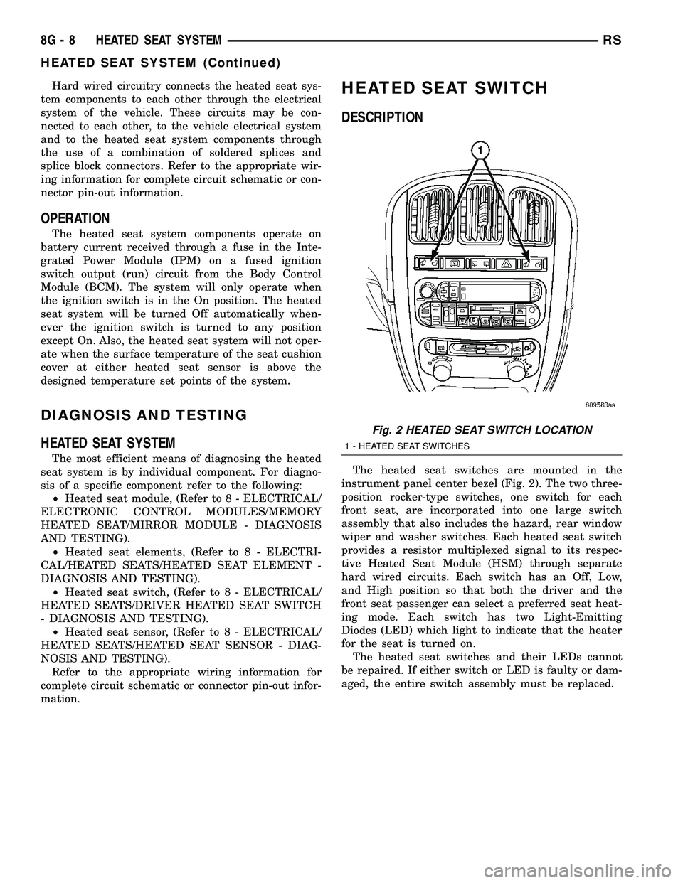
The heated seat switches are mounted in the
instrument panel center bezel (Fig. 2). The two three-
position rocker-type switches, one switch for each
front seat, are incorporated into one large switch
assembly that also includes the hazard, rear window
wiper and washer switches. Each heated seat switch
provides a resistor multiplexed signal to its respec-
tive Heated Seat Module (HSM) through separate
hard wired circuits. Each switch has an Off, Low,
and High position so that both the driver and the
front seat passenger can select a preferred seat heat-
ing mode. Each switch has two Light-Emitting
Diodes (LED) which light to indicate that the heater
for the seat is turned on.
The heated seat switches and their LEDs cannot
be repaired. If either switch or LED is faulty or dam-
aged, the entire switch assembly must be replaced.
Fig. 2 HEATED SEAT SWITCH LOCATION
1 - HEATED SEAT SWITCHES
8G - 8 HEATED SEAT SYSTEMRS
HEATED SEAT SYSTEM (Continued)
Page 360 of 2339
HORN
TABLE OF CONTENTS
page page
HORN SYSTEM
DESCRIPTION..........................1
OPERATION............................1
DIAGNOSIS AND TESTING
HORN SYSTEM........................1
HORN
DIAGNOSIS AND TESTING
HORN...............................3REMOVAL.............................4
INSTALLATION..........................4
HORN SWITCH
DESCRIPTION..........................4
HORN SYSTEM
DESCRIPTION
WARNING: ON VEHICLES EQUIPPED WITH AIR-
BAG, REFER TO ELECTRICAL, RESTRAINTS FOR
SAFETY PRECAUTIONS. DISCONNECT THE NEGA-
TIVE CABLE FROM THE BATTERY BEFORE SER-
VICING COMPONENTS INVOLVING THE AIRBAG
SYSTEM. ACCIDENTAL DEPLOYMENT OF AIRBAG
AND PERSONAL INJURY CAN RESULT.
The horn circuit consists of a horn switch, clock-
spring, horn relay, horns and Integrated Power Mod-
ule (IPM). The horn switch is a membrane switch
located in the airbag trim cover. The horns are
located forward of the left front wheel behind the
bumper fascia.
OPERATION
The horn relay plugs into the Integrated Power
Module (IPM) which is located in the engine com-
partment. For circuit information and component
locations, refer to the appropriate wiring information.
The wiring information includes wiring diagrams,
proper wire and connector repair procedures, details
of wire harness routing and retention, connector pin-
out information and location views for the various
wire harness connectors, splices and grounds.
The horns will not function if the switch is
ªCLOSEDº for more than 30 seconds. Once the
switch is ªOPENº, a 20±30 second delay will occur
before the horns are functional again.
DIAGNOSIS AND TESTING
HORN SYSTEM
WARNING: ON VEHICLES EQUIPPED WITH AIR-
BAGS, REFER TO ELECTRICAL, RESTRAINTS
BEFORE ATTEMPTING ANY STEERING WHEEL,
STEERING COLUMN, OR INSTRUMENT PANEL
COMPONENT DIAGNOSIS OR SERVICE. FAILURE
TO TAKE THE PROPER PRECAUTIONS COULD
RESULT IN ACCIDENTAL AIRBAG DEPLOYMENT
AND POSSIBLE PERSONAL INJURY.
Refer to Horn System Test below. If the horn does
not sound, check horn fuse located in the Integrated
Power Module (IPM). If the fuse is blown, replace
with the correct fuse. If the horns fail to sound and
the new fuse blows when depressing the horn switch,
a short circuit in the horn or the horn wiring
between the fuse terminal and the horn is responsi-
ble, or a defective horn switch allowed the horn to
burn out is responsible.
If the fuse is OK, test horn relay.
If the relay is OK, test horn.
CAUTION: Continuous sounding of horn may
cause horn failure.
Should the horn sound continuously, unplug the
horn relay from IPM.
Refer to the appropriate wiring information.
RSHORN8H-1