CHRYSLER PACIFICA HYBRID 2019 Owners Manual
Manufacturer: CHRYSLER, Model Year: 2019, Model line: PACIFICA HYBRID, Model: CHRYSLER PACIFICA HYBRID 2019Pages: 620, PDF Size: 4.92 MB
Page 401 of 620
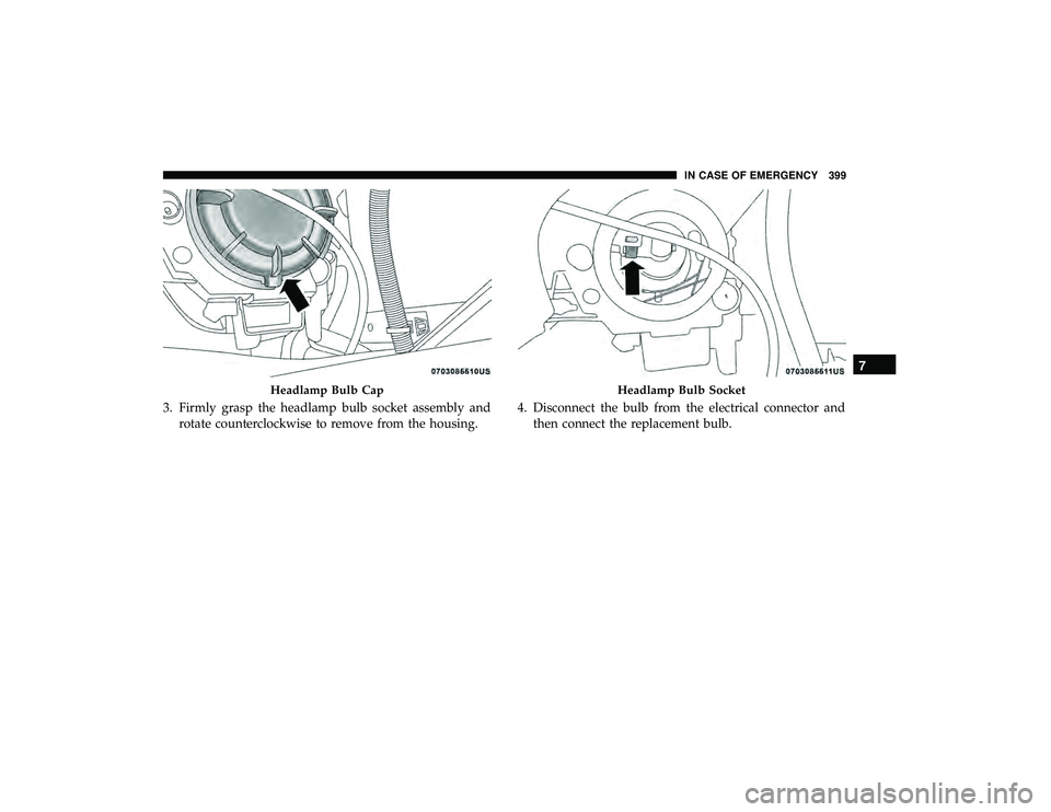
3. Firmly grasp the headlamp bulb socket assembly androtate counterclockwise to remove from the housing. 4. Disconnect the bulb from the electrical connector and
then connect the replacement bulb.
Headlamp Bulb CapHeadlamp Bulb Socket
7
IN CASE OF EMERGENCY 399
Page 402 of 620
CAUTION!
Do not touch the new bulb with your fingers. Oil
contamination will severely shorten bulb life. If the
bulb comes in contact with any oily surface, clean the
bulb with rubbing alcohol.
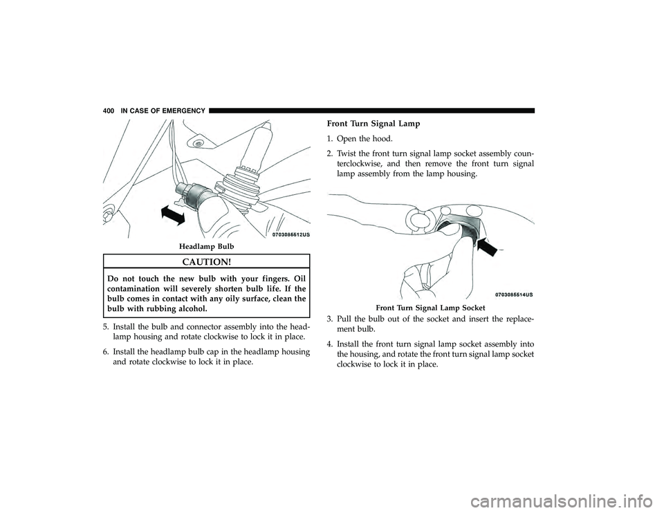
5. Install the bulb and connector assembly into the head- lamp housing and rotate clockwise to lock it in place.
6. Install the headlamp bulb cap in the headlamp housing and rotate clockwise to lock it in place.
Front Turn Signal Lamp
1. Open the hood.
2. Twist the front turn signal lamp socket assembly coun-terclockwise, and then remove the front turn signal
lamp assembly from the lamp housing.
3. Pull the bulb out of the socket and insert the replace- ment bulb.
4. Install the front turn signal lamp socket assembly into the housing, and rotate the front turn signal lamp socket
clockwise to lock it in place.
Headlamp Bulb
Front Turn Signal Lamp Socket
400 IN CASE OF EMERGENCY
Page 403 of 620
Front And Rear Side Marker Lamps
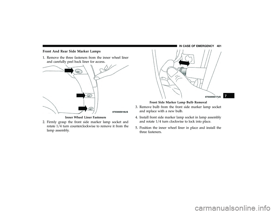
1. Remove the three fasteners from the inner wheel linerand carefully peel back liner for access.
2. Firmly grasp the front side marker lamp socket and rotate 1/4 turn counterclockwise to remove it from the
lamp assembly. 3. Remove bulb from the front side marker lamp socket
and replace with a new bulb.
4. Install front side marker lamp socket in lamp assembly and rotate 1/4 turn clockwise to lock into place.
5. Position the inner wheel liner in place and install the three fasteners.
Inner Wheel Liner Fasteners
Front Side Marker Lamp Bulb Removal
7
IN CASE OF EMERGENCY 401
Page 404 of 620
Front Fog Lamp — Halogen
1. Remove fasteners from inner wheel liner and carefullypeel back liner for access.
2. Reach through the front fascia to fog lamp housing to access the bulb.
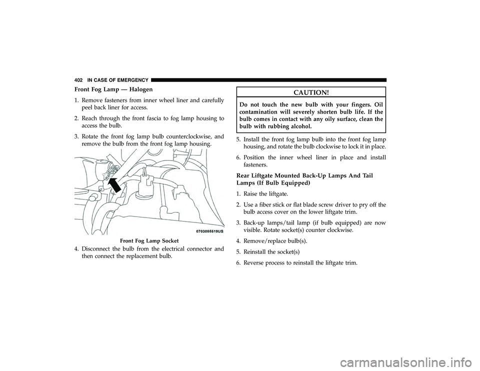
3. Rotate the front fog lamp bulb counterclockwise, and remove the bulb from the front fog lamp housing.
4. Disconnect the bulb from the electrical connector and then connect the replacement bulb.
CAUTION!
Do not touch the new bulb with your fingers. Oil
contamination will severely shorten bulb life. If the
bulb comes in contact with any oily surface, clean the
bulb with rubbing alcohol.
5. Install the front fog lamp bulb into the front fog lamp housing, and rotate the bulb clockwise to lock it in place.
6. Position the inner wheel liner in place and install fasteners.
Rear Liftgate Mounted Back-Up Lamps And Tail
Lamps (If Bulb Equipped)
1. Raise the liftgate.
2. Use a fiber stick or flat blade screw driver to pry off thebulb access cover on the lower liftgate trim.
3. Back-up lamps/tail lamp (if bulb equipped) are now visible. Rotate socket(s) counter clockwise.
4. Remove/replace bulb(s).
5. Reinstall the socket(s)
6. Reverse process to reinstall the liftgate trim.
Front Fog Lamp Socket
402 IN CASE OF EMERGENCY
Page 405 of 620
Rear Bodyside Mounted Taillamps
1. Raise the liftgate.
2. Remove two torx head screws on bodyside lamp usinga T30 screwdriver.
3. Remove lamp from vehicle body and locate bulb socket on rear of lamp. Rotate socket counter-clockwise.
4. Remove/replace bulb(s).
5. Reinstall the socket(s)
6. Reverse process to reinstall the lamp onto vehicle.
Center High-Mounted Stop Lamp (CHMSL)
The center high-mounted stop lamp is an LED assembly.
See your authorized dealer for replacement.
Rear License Lamp
The rear license lamps are LED. See your authorized dealer
for replacement.
FUSES
WARNING!
• When replacing a blown fuse, always use an appro-
priate replacement fuse with the same amp rating as
the original fuse. Never replace a fuse with another
fuse of higher amp rating. Never replace a blown
fuse with metal wires or any other material. Do not
place a fuse inside a circuit breaker cavity or vice
versa. Failure to use proper fuses may result in
serious personal injury, fire and/or property damage.
• Before replacing a fuse, make sure that the ignition is
off and that all the other services are switched off
and/or disengaged.
• If the replaced fuse blows again, contact an autho-
rized dealer.
• If a general protection fuse for safety systems (air
bag system, braking system), power unit systems
(engine system, transmission system) or steering
system blows, contact an authorized dealer.
7
IN CASE OF EMERGENCY 403
Page 406 of 620
General Information
The fuses protect electrical systems against excessive cur-
rent.
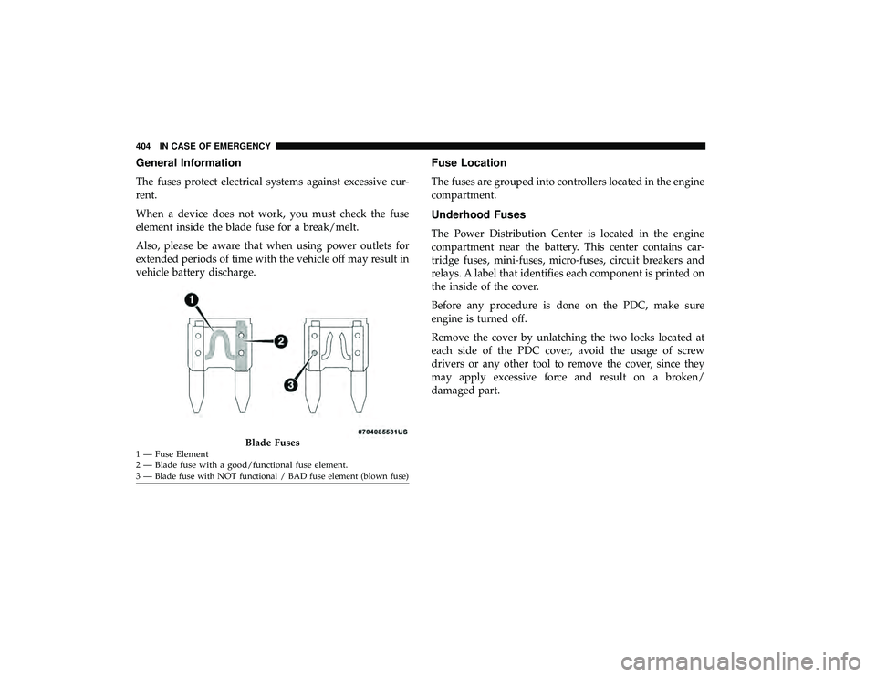
When a device does not work, you must check the fuse
element inside the blade fuse for a break/melt.
Also, please be aware that when using power outlets for
extended periods of time with the vehicle off may result in
vehicle battery discharge.
Fuse Location
The fuses are grouped into controllers located in the engine
compartment.
Underhood Fuses
The Power Distribution Center is located in the engine
compartment near the battery. This center contains car-
tridge fuses, mini-fuses, micro-fuses, circuit breakers and
relays. A label that identifies each component is printed on
the inside of the cover.
Before any procedure is done on the PDC, make sure
engine is turned off.
Remove the cover by unlatching the two locks located at
each side of the PDC cover, avoid the usage of screw
drivers or any other tool to remove the cover, since they
may apply excessive force and result on a broken/
damaged part.
Blade Fuses1 — Fuse Element
2 — Blade fuse with a good/functional fuse element.
3—
Blade fuse with NOT functional / BAD fuse element (blown fuse)
404 IN CASE OF EMERGENCY
Page 407 of 620
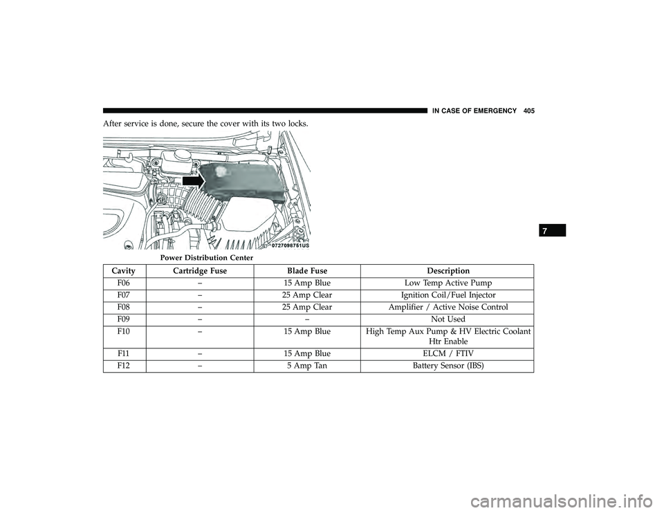
After service is done, secure the cover with its two locks.
Cavity Cartridge FuseBlade FuseDescription
F06 – 15 Amp Blue Low Temp Active Pump
F07 – 25 Amp Clear Ignition Coil/Fuel Injector
F08 – 25 Amp Clear Amplifier / Active Noise Control
F09 – – Not Used
F10 – 15 Amp Blue High Temp Aux Pump & HV Electric Coolant
Htr Enable
F11 – 15 Amp Blue ELCM / FTIV
F12 – 5 Amp Tan Battery Sensor (IBS)
Power Distribution Center
7
IN CASE OF EMERGENCY 405
Page 408 of 620
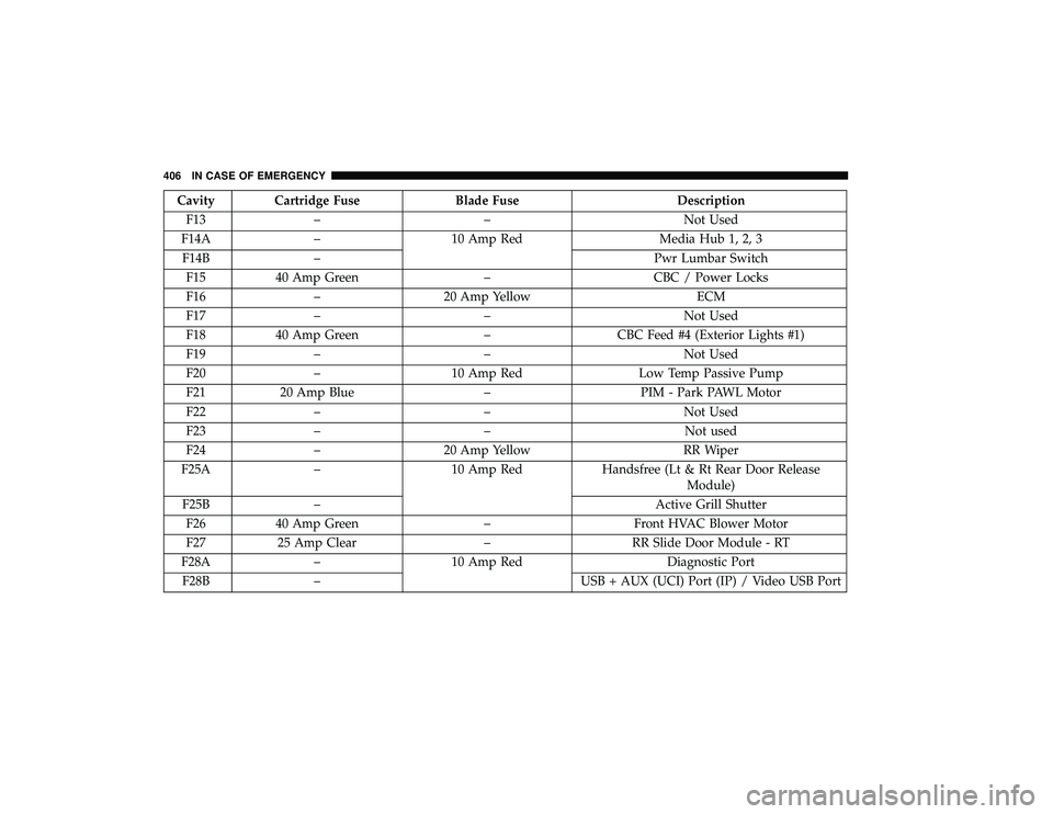
Cavity Cartridge FuseBlade FuseDescription
F13 – – Not Used
F14A – 10 Amp Red Media Hub 1, 2, 3
F14B – Pwr Lumbar Switch
F15 40 Amp Green –CBC / Power Locks
F16 – 20 Amp Yellow ECM
F17 – – Not Used
F18 40 Amp Green –CBC Feed #4 (Exterior Lights #1)
F19 – – Not Used
F20 – 10 Amp Red Low Temp Passive Pump
F21 20 Amp Blue –PIM - Park PAWL Motor
F22 – – Not Used
F23 – – Not used
F24 – 20 Amp Yellow RR Wiper
F25A – 10 Amp Red Handsfree (Lt & Rt Rear Door Release
Module)
F25B – Active Grill Shutter
F26 40 Amp Green –Front HVAC Blower Motor
F27 25 Amp Clear –RR Slide Door Module - RT
F28A – 10 Amp Red Diagnostic Port
F28B – USB + AUX (UCI) Port (IP) / Video USB Port
406 IN CASE OF EMERGENCY
Page 409 of 620
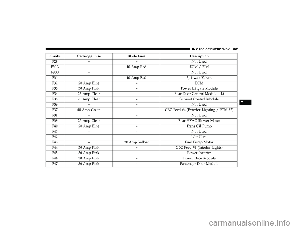
Cavity Cartridge FuseBlade FuseDescription
F29 – – Not Used
F30A – 10 Amp Red ECM / PIM
F30B – Not Used
F31 – 10 Amp Red 3, 4 way Valves
F32 20 Amp Blue – ECM
F33 30 Amp Pink –Power Liftgate Module
F34 25 Amp Clear –Rear Door Control Module - Lt
F35 25 Amp Clear –Sunroof Control Module
F36 – – Not Used
F37 40 Amp Green –CBC Feed #4 (Exterior Lighting / PCM #2)
F38 – – Not Used
F39 25 Amp Clear –Rear HVAC Blower Motor
F40 20 Amp Blue –Trans Oil Pump
F41 – – Not Used
F42 – – Not Used
F43 – 20 Amp Yellow Fuel Pump Motor
F44 30 Amp Pink –CBC Feed #1 (Interior Lights)
F45 30 Amp Pink –Power Inverter
F46 30 Amp Pink –Driver Door Module
F47 30 Amp Pink –Passenger Door Module
7
IN CASE OF EMERGENCY 407
Page 410 of 620
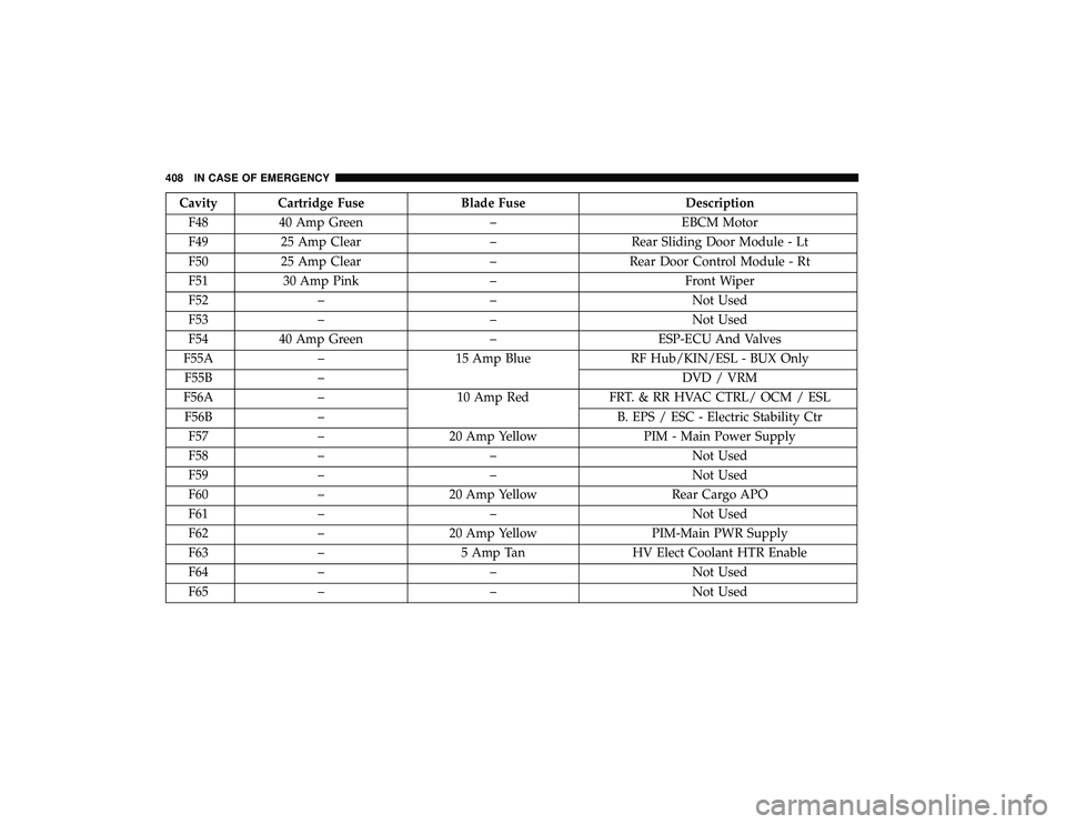
Cavity Cartridge FuseBlade FuseDescription
F48 40 Amp Green –EBCM Motor
F49 25 Amp Clear –Rear Sliding Door Module - Lt
F50 25 Amp Clear –Rear Door Control Module - Rt
F51 30 Amp Pink –Front Wiper
F52 – – Not Used
F53 – – Not Used
F54 40 Amp Green –ESP-ECU And Valves
F55A – 15 Amp Blue RF Hub/KIN/ESL - BUX Only
F55B – DVD / VRM
F56A – 10 Amp Red FRT. & RR HVAC CTRL/ OCM / ESL
F56B – B. EPS / ESC - Electric Stability Ctr
F57 – 20 Amp Yellow PIM - Main Power Supply
F58 – – Not Used
F59 – – Not Used
F60 – 20 Amp Yellow Rear Cargo APO
F61 – – Not Used
F62 – 20 Amp Yellow PIM-Main PWR Supply
F63 – 5 Amp Tan HV Elect Coolant HTR Enable
F64 – – Not Used
F65 – – Not Used
408 IN CASE OF EMERGENCY