CHRYSLER SEBRING COUPE 2005 2.G Owners Manual
Manufacturer: CHRYSLER, Model Year: 2005, Model line: SEBRING COUPE, Model: CHRYSLER SEBRING COUPE 2005 2.GPages: 394, PDF Size: 2.47 MB
Page 301 of 394
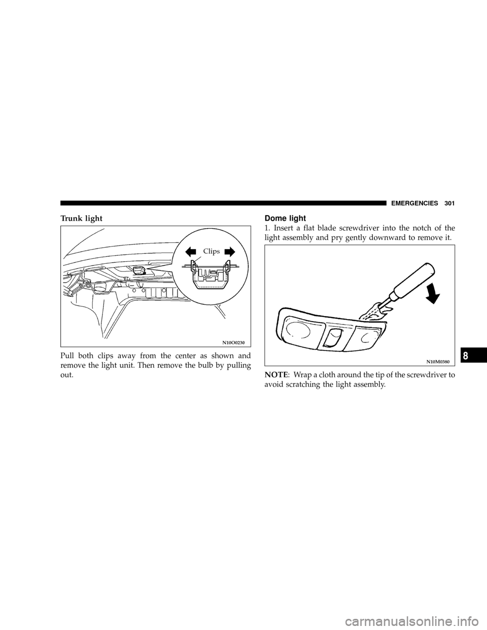
Trunk light
Pull both clips away from the center as shown and
remove the light unit. Then remove the bulb by pulling
out.
Dome light
1. Insert a flat blade screwdriver into the notch of the
light assembly and pry gently downward to remove it.
NOTE: Wrap a cloth around the tip of the screwdriver to
avoid scratching the light assembly.
N10O0230
Clips
N10M0380
EMERGENCIES 301
8
Page 302 of 394
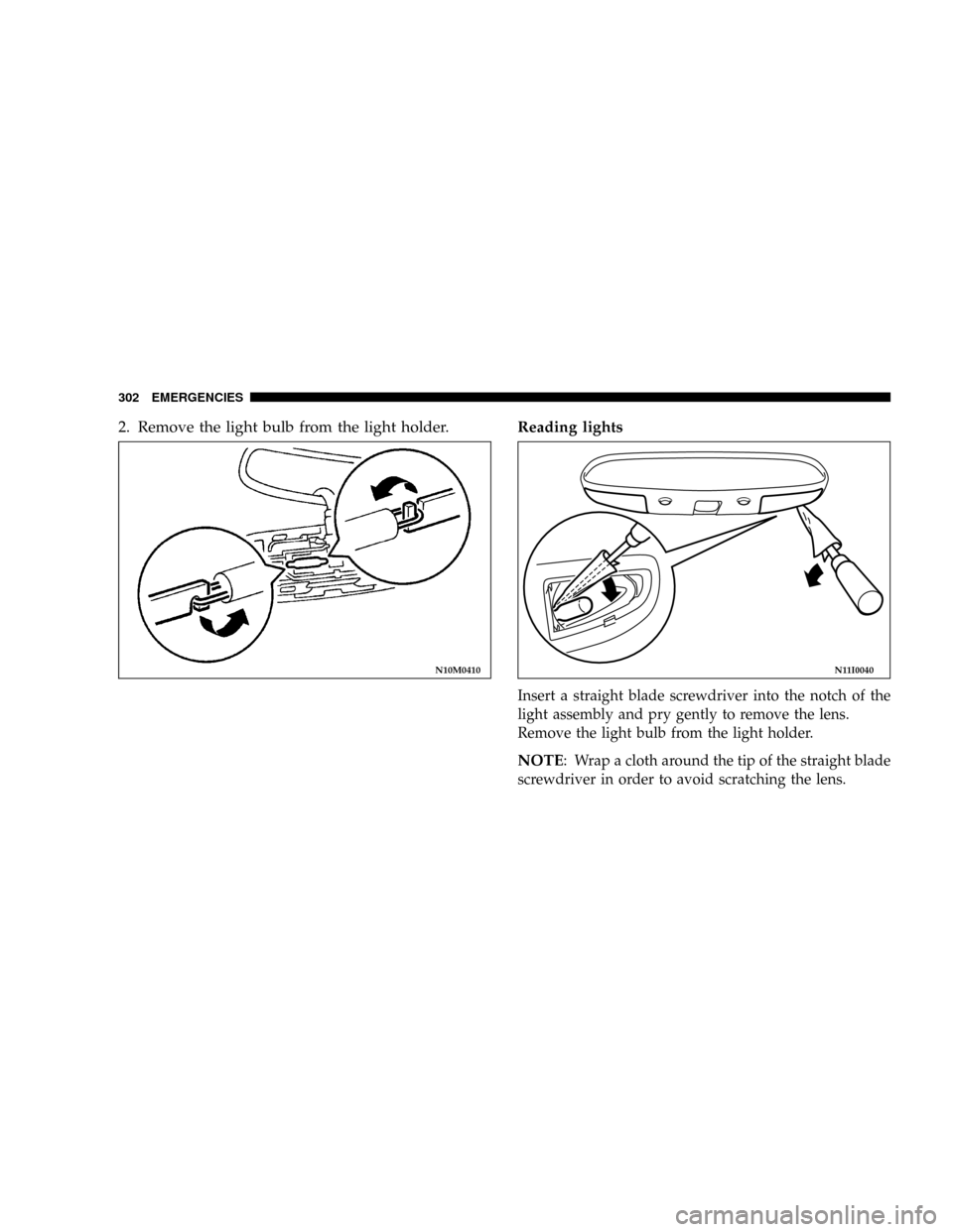
2. Remove the light bulb from the light holder.Reading lights
Insert a straight blade screwdriver into the notch of the
light assembly and pry gently to remove the lens.
Remove the light bulb from the light holder.
NOTE: Wrap a cloth around the tip of the straight blade
screwdriver in order to avoid scratching the lens.
N10M0410N11I0040
302 EMERGENCIES
Page 303 of 394
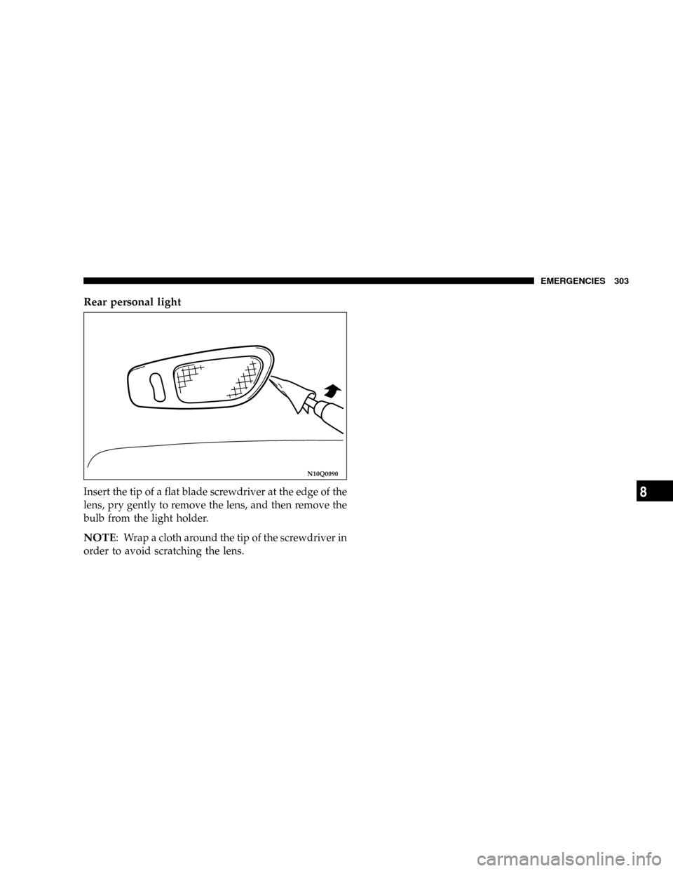
Rear personal light
Insert the tip of a flat blade screwdriver at the edge of the
lens, pry gently to remove the lens, and then remove the
bulb from the light holder.
NOTE: Wrap a cloth around the tip of the screwdriver in
order to avoid scratching the lens.
N10Q0090
EMERGENCIES 303
8
Page 304 of 394

Page 305 of 394
MAINTENANCE
CONTENTS
mView of engine compartment..............307
mService precautions.....................308
mEmission-control system maintenance.......309
mEmissions Testing......................310
mOnboard Diagnostic System (OBD II)........310
mReplacement Parts......................311
NFuel system (tank, filler tube, connections,
and fuel tank filler cap).................311
NFuel hoses...........................311
NAir cleaner filter......................312
NEvaporative emission control system
(except evaporative emission canister).......312
NSpark plugs..........................313
NIgnition cables........................313NDistributor cap and rotor................313
mGeneral maintenance....................314
NEngine oil and oil filter..................314
mEngine coolant.........................318
NTo check the coolant level................318
NTo add coolant........................318
mBrake fluid...........................319
mClutch fluid (manual transaxle)............320
NTo check the clutch fluid.................320
NTo replace the fluid....................320
mBattery..............................321
NDuring cold weather...................323
9
Page 306 of 394

NDisconnection and connection.............323
mAutomatic transaxle.....................325
NTo check the fluid level..................326
NProcedure for checking the fluid level.......326
mManual transaxle.......................327
mDisc brake pads, rear drum brake linings
and rear wheel cylinders.................327
mBrake hoses...........................327
mBall joint, steering linkage seal and drive
shaft boots...........................327
mSupplemental Restraint System (SRS)........327
mHood lock release mechanism and safety
catch
................................328
mExhaust system........................328
mWindshield wiper blades.................329
NWindshield washers....................329
mParking brake.........................330
mDrive belt (for generator, water pump, power
steering pump)
........................331
mTiming belt...........................332
mTi re s................................332
NTire inflation pressures..................336
NRadial ply tires.......................337
N
Tire pressure for sustained high-speed driving...338
NReplacing tire and wheels................338
NTire maintenance......................338
NCargo loads..........................343
NTread wear indicators...................343
NTire rotation.........................344
NTire chains...........................345
NSnow tires...........................345
mRegular Maintenance Schedule.............346
mSevere Maintenance Schedule..............354
306 MAINTENANCE
Page 307 of 394
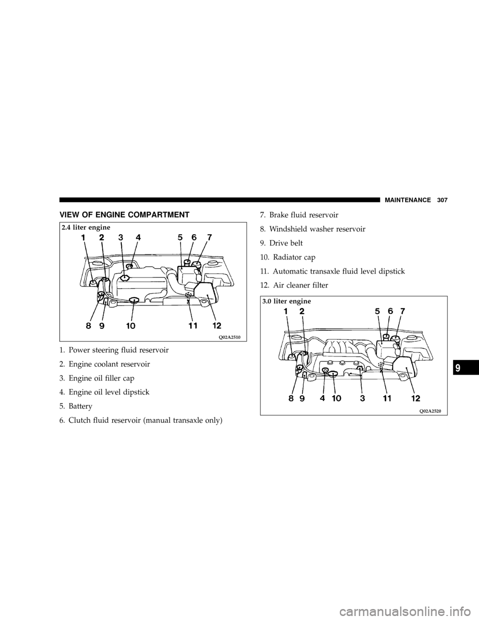
VIEW OF ENGINE COMPARTMENT
1. Power steering fluid reservoir
2. Engine coolant reservoir
3. Engine oil filler cap
4. Engine oil level dipstick
5. Battery
6. Clutch fluid reservoir (manual transaxle only)7. Brake fluid reservoir
8. Windshield washer reservoir
9. Drive belt
10. Radiator cap
11. Automatic transaxle fluid level dipstick
12. Air cleaner filter
Q02A2510
2.4 liter engine
Q02A2520
3.0 liter engine
MAINTENANCE 307
9
Page 308 of 394
NOTE: The Scheduled Maintenance Charts are located
in the rear of this maintenance section. Always refer to
the schedules for proper service intervals.
SERVICE PRECAUTIONS
Adequate care of your vehicle at regular intervals serves
to preserve the value and appearance as long as possible.
Some maintenance items can be performed by the owner,
while others should be done only by an authorized
dealer.
This section describes only those items which can be
performed by the owner. In the event a malfunction or
other problem is discovered, have it corrected by an
authorized dealer.
This section contains information on inspection mainte-
nance procedures that you can do yourself, if you so
desire. Follow the instructions and precautions for each
of the various procedures.
WARNING!
²When checking or servicing the inside of the
engine compartment, be sure the engine is
stopped and has had a chance to cool down.
²If it is necessary to do work in the engine com-
partment with the engine running, be especially
careful that your clothing, hair, etc. does not
become caught by the fan, drive belts, or other
moving parts.
308 MAINTENANCE
Page 309 of 394
WARNING!
²The fan may turn on automatically even if the
engine is not running; turn the ignition key to the
ªLOCKº position and remove the key to ensure
safety while you work in the engine compartment.
²Do not smoke, or allow open flames around fuel
or the battery. The fumes are flammable.
²Be extremely cautious when working around the
battery. It contains poisonous and corrosive sulfu-
ric acid.
²Do not get under your vehicle with just the car's
jack supporting it.
Always use properly rated automotive jack
stands.
²Improper handling of components and materials
used in the vehicle can endanger your personal
safety. Consult an authorized dealer if you have
questions.
EMISSION-CONTROL SYSTEM MAINTENANCE
Your vehicle is equipped with an emission-control sys-
tem which satisfies all requirements of the U.S. Environ-
mental Protection Agency. The emission-control system
consists of:
(1) a positive crankcase ventilation system
(2) an evaporative emission-control system
(3) an exhaust emission- control system.
The9Scheduled9maintenance services listed must be
performed at the times or mileages specified to assure the
continued proper functioning of the emission-control
system. These, and all other ªGeneralº maintenance
services included in this manual, should be performed to
provide the best vehicle performance and reliability.
More frequent maintenance may be needed for vehicles
driven under severe operating conditions such as dusty
areas and frequent start and stop driving.
In order to assure the proper function of the emission-
control system, it is recommended that you have your
vehicle inspected and maintained by an authorized
dealer in accordance with the schedule in this manual.
Inspection and service should also be performed any
time a malfunction is suspected.
MAINTENANCE 309
9
Page 310 of 394
EMISSIONS TESTING
In some localities, it may be or will become a legal
requirement to ensure that all emissions components and
systems are functioning properly as a part of the test
procedure. The test center accomplishes this by checking
the On Board Diagnostic System system (OBD) with an
electronic scan tool. If your vehicle has recently been
serviced, the OBD system may have been reset to a9not
ready9condition because the OBD system has not had
sufficient time since the servicing to reconfirm that
emissions components are operating properly. In most
cases, a reasonable mix and amount of normal city and
highway driving and at least one overnight-off period
will be required to prepare your vehicle for this check;
however your DaimlerChrysler Motors Corporation
dealer has the equipment and procedures required to
make certain that the OBD system of your vehicle is
ready for the required testing.
ONBOARD DIAGNOSTIC SYSTEM (OBD II)
To meet new government regulations and promote
cleaner air, your vehicle is equipped with a sophisticated
onboard diagnostic system called OBD II. This systemmonitors the performance of the emissions, engine, and
automatic transaxle control systems. When these systems
are operating properly, your vehicle will provide excel-
lent performance and fuel economy, as well as engine
emissions well within current government regulations.
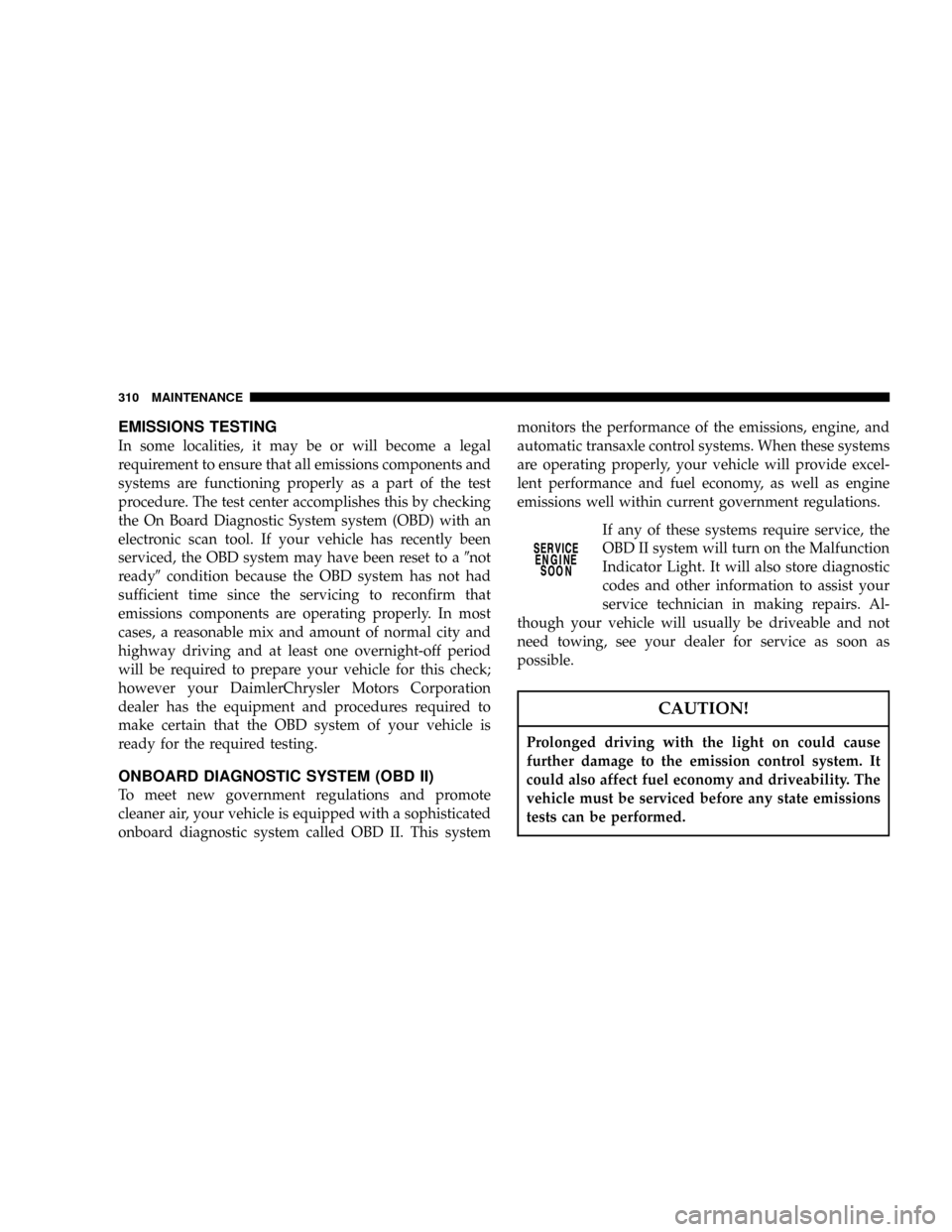
If any of these systems require service, the
OBD II system will turn on the Malfunction
Indicator Light. It will also store diagnostic
codes and other information to assist your
service technician in making repairs. Al-
though your vehicle will usually be driveable and not
need towing, see your dealer for service as soon as
possible.
CAUTION!
Prolonged driving with the light on could cause
further damage to the emission control system. It
could also affect fuel economy and driveability. The
vehicle must be serviced before any state emissions
tests can be performed.
310 MAINTENANCE