Engine ground CHRYSLER TOWN AND COUNTRY 2002 User Guide
[x] Cancel search | Manufacturer: CHRYSLER, Model Year: 2002, Model line: TOWN AND COUNTRY, Model: CHRYSLER TOWN AND COUNTRY 2002Pages: 2399, PDF Size: 57.96 MB
Page 293 of 2399
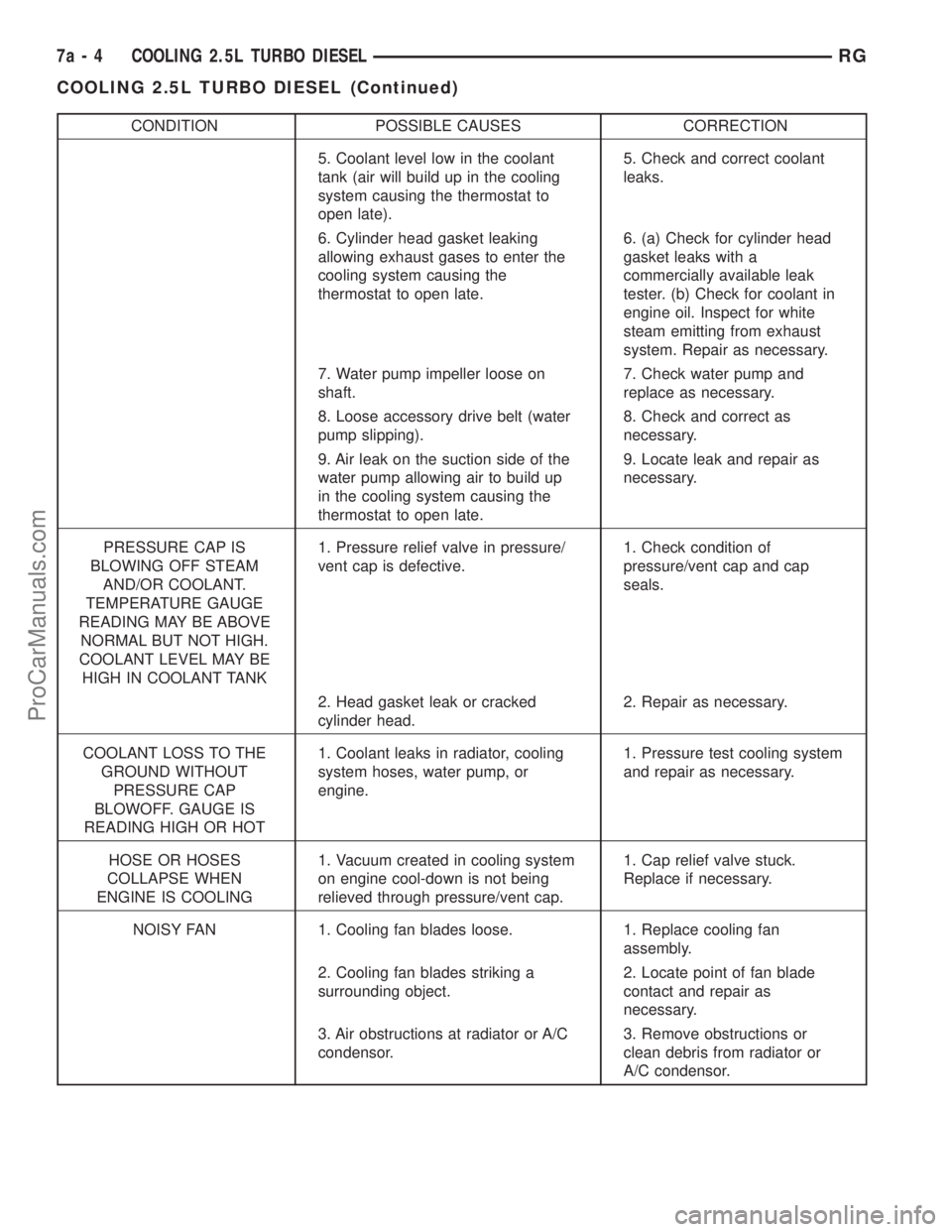
CONDITION POSSIBLE CAUSES CORRECTION
5. Coolant level low in the coolant
tank (air will build up in the cooling
system causing the thermostat to
open late).5. Check and correct coolant
leaks.
6. Cylinder head gasket leaking
allowing exhaust gases to enter the
cooling system causing the
thermostat to open late.6. (a) Check for cylinder head
gasket leaks with a
commercially available leak
tester. (b) Check for coolant in
engine oil. Inspect for white
steam emitting from exhaust
system. Repair as necessary.
7. Water pump impeller loose on
shaft.7. Check water pump and
replace as necessary.
8. Loose accessory drive belt (water
pump slipping).8. Check and correct as
necessary.
9. Air leak on the suction side of the
water pump allowing air to build up
in the cooling system causing the
thermostat to open late.9. Locate leak and repair as
necessary.
PRESSURE CAP IS
BLOWING OFF STEAM
AND/OR COOLANT.
TEMPERATURE GAUGE
READING MAY BE ABOVE
NORMAL BUT NOT HIGH.
COOLANT LEVEL MAY BE
HIGH IN COOLANT TANK1. Pressure relief valve in pressure/
vent cap is defective.1. Check condition of
pressure/vent cap and cap
seals.
2. Head gasket leak or cracked
cylinder head.2. Repair as necessary.
COOLANT LOSS TO THE
GROUND WITHOUT
PRESSURE CAP
BLOWOFF. GAUGE IS
READING HIGH OR HOT1. Coolant leaks in radiator, cooling
system hoses, water pump, or
engine.1. Pressure test cooling system
and repair as necessary.
HOSE OR HOSES
COLLAPSE WHEN
ENGINE IS COOLING1. Vacuum created in cooling system
on engine cool-down is not being
relieved through pressure/vent cap.1. Cap relief valve stuck.
Replace if necessary.
NOISY FAN 1. Cooling fan blades loose. 1. Replace cooling fan
assembly.
2. Cooling fan blades striking a
surrounding object.2. Locate point of fan blade
contact and repair as
necessary.
3. Air obstructions at radiator or A/C
condensor.3. Remove obstructions or
clean debris from radiator or
A/C condensor.
7a - 4 COOLING 2.5L TURBO DIESELRG
COOLING 2.5L TURBO DIESEL (Continued)
ProCarManuals.com
Page 318 of 2399
RADIATOR FAN RELAY
DESCRIPTION
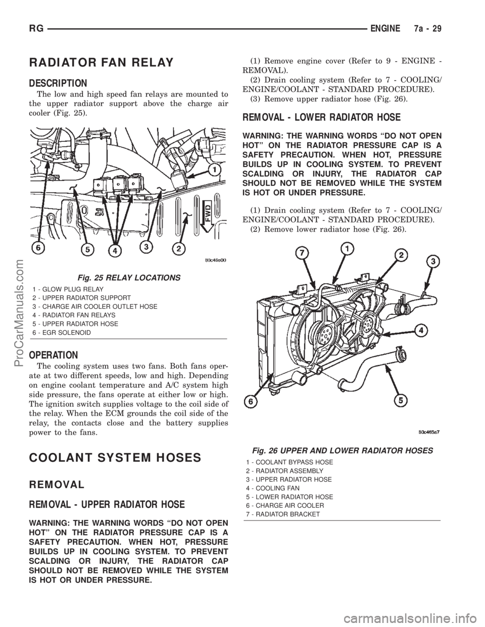
The low and high speed fan relays are mounted to
the upper radiator support above the charge air
cooler (Fig. 25).
OPERATION
The cooling system uses two fans. Both fans oper-
ate at two different speeds, low and high. Depending
on engine coolant temperature and A/C system high
side pressure, the fans operate at either low or high.
The ignition switch supplies voltage to the coil side of
the relay. When the ECM grounds the coil side of the
relay, the contacts close and the battery supplies
power to the fans.
COOLANT SYSTEM HOSES
REMOVAL
REMOVAL - UPPER RADIATOR HOSE
WARNING: THE WARNING WORDS ªDO NOT OPEN
HOTº ON THE RADIATOR PRESSURE CAP IS A
SAFETY PRECAUTION. WHEN HOT, PRESSURE
BUILDS UP IN COOLING SYSTEM. TO PREVENT
SCALDING OR INJURY, THE RADIATOR CAP
SHOULD NOT BE REMOVED WHILE THE SYSTEM
IS HOT OR UNDER PRESSURE.(1) Remove engine cover (Refer to 9 - ENGINE -
REMOVAL).
(2) Drain cooling system (Refer to 7 - COOLING/
ENGINE/COOLANT - STANDARD PROCEDURE).
(3) Remove upper radiator hose (Fig. 26).
REMOVAL - LOWER RADIATOR HOSE
WARNING: THE WARNING WORDS ªDO NOT OPEN
HOTº ON THE RADIATOR PRESSURE CAP IS A
SAFETY PRECAUTION. WHEN HOT, PRESSURE
BUILDS UP IN COOLING SYSTEM. TO PREVENT
SCALDING OR INJURY, THE RADIATOR CAP
SHOULD NOT BE REMOVED WHILE THE SYSTEM
IS HOT OR UNDER PRESSURE.
(1) Drain cooling system (Refer to 7 - COOLING/
ENGINE/COOLANT - STANDARD PROCEDURE).
(2) Remove lower radiator hose (Fig. 26).
Fig. 25 RELAY LOCATIONS
1 - GLOW PLUG RELAY
2 - UPPER RADIATOR SUPPORT
3 - CHARGE AIR COOLER OUTLET HOSE
4 - RADIATOR FAN RELAYS
5 - UPPER RADIATOR HOSE
6 - EGR SOLENOID
Fig. 26 UPPER AND LOWER RADIATOR HOSES
1 - COOLANT BYPASS HOSE
2 - RADIATOR ASSEMBLY
3 - UPPER RADIATOR HOSE
4 - COOLING FAN
5 - LOWER RADIATOR HOSE
6 - CHARGE AIR COOLER
7 - RADIATOR BRACKET
RGENGINE7a-29
ProCarManuals.com
Page 329 of 2399
(9) Disconnect the wire connectors from the back
of the radio.
INSTALLATION
(1) Connect wire harness to back of radio.
(2) Install bolt holding ground strap to the radio (if
equipped).
(3) Connect antenna cable to back of radio.
(4) Position radio into instrument panel.
(5) Install screws holding radio to instrument
panel.
(6) Install center instrument panel trim.
(7) Install trim panel above cupholder.
(8) Install cupholder.
(9) Connect battery negative cable.
RADIO NOISE SUPPRESSION
COMPONENTS
DESCRIPTION
Radio noise suppression devices are factory-in-
stalled standard equipment on this vehicle. Radio
Frequency Interference (RFI) and ElectroMagnetic
Interference (EMI) can be produced by any on-board
or external source of electromagnetic energy. These
electromagnetic energy sources can radiate electro-
magnetic signals through the air, or conduct them
through the vehicle electrical system.
When the audio system converts RFI or EMI to an
audible acoustic wave form, it is referred to as radionoise. This undesirable radio noise is generally man-
ifested in the form of ªbuzzing,º ªhissing,º ªpopping,º
ªclicking,º ªcrackling,º and/or ªwhirringº sounds. In
most cases, RFI and EMI radio noise can be sup-
pressed using a combination of vehicle and compo-
nent grounding, filtering and shielding techniques.
This vehicle is equipped with factory-installed radio
noise suppression devices that were designed to min-
imize exposure to typical sources of RFI and EMI;
thereby, minimizing radio noise complaints.
Factory-installed radio noise suppression is accom-
plished primarily through circuitry or devices that
are integral to the factory-installed radios, audio
power amplifiers and other on-board electrical com-
ponents such as generators, wiper motors, blower
motors, and fuel pumps that have been found to be
potential sources of RFI or EMI.
OPERATION
There are two common strategies that can be used
to suppress Radio Frequency Interference (RFI) and
ElectroMagnetic Interference (EMI) radio noise. The
first suppression strategy involves preventing the
production of RFI and EMI electromagnetic signals
at their sources. The second suppression strategy
involves preventing the reception of RFI and EMI
electromagnetic signals by the audio system compo-
nents.
The use of braided ground straps in key locations
is part of the RFI and EMI prevention strategy.
These ground straps ensure adequate ground paths,
particularly for high current components such as
many of those found in the starting, charging, igni-
tion, engine control and transmission control sys-
tems. An insufficient ground path for any of these
high current components may result in radio noise
caused by induced voltages created as the high cur-
rent seeks alternative ground paths through compo-
nents or circuits intended for use by, or in close
proximity to the audio system components or circuits.
Preventing the reception of RFI and EMI is accom-
plished by ensuring that the audio system compo-
nents are correctly installed in the vehicle. Loose,
corroded or improperly soldered wire harness connec-
tions, improperly routed wiring and inadequate audio
system component grounding can all contribute to
the reception of RFI and EMI. A properly grounded
antenna body and radio chassis, as well as a shielded
antenna coaxial cable with clean and tight connec-
tions will each help reduce the potential for reception
of RFI and EMI.
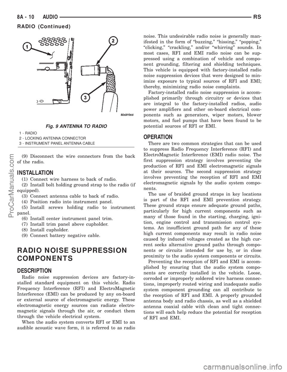
Fig. 9 ANTENNA TO RADIO
1 - RADIO
2 - LOCKING ANTENNA CONNECTOR
3 - INSTRUMENT PANEL ANTENNA CABLE
8A - 10 AUDIORS
RADIO (Continued)
ProCarManuals.com
Page 334 of 2399
CHIME/BUZZER
TABLE OF CONTENTS
page page
CHIME/BUZZER
DESCRIPTION..........................1
OPERATION............................1
WARNING.............................1
DIAGNOSIS AND TESTING
DIAGNOSIS AND TESTING - CHIME
SYSTEM.............................1
DIAGNOSIS AND TESTING - DOME LAMP
ON CHIME............................2
DIAGNOSIS AND TESTING - ENGINE
TEMPERATURE CRITICAL CHIME..........2
DIAGNOSIS AND TESTING - EXTERIOR
LAMPS ON CHIME.....................2
DIAGNOSIS AND TESTING - KEY-IN
IGNITION CHIME.......................2DIAGNOSIS AND TESTING - LOW OIL
PRESSURE CHIME.....................3
DIAGNOSIS AND TESTING - SEAT BELT
CHIME...............................3
DIAGNOSIS AND TESTING - SEAT BELT
LAMP...............................3
DIAGNOSIS AND TESTING - TIRE
PRESSURE MONITOR..................3
DIAGNOSIS AND TESTING - TURN SIGNAL
ON CHIME............................3
DIAGNOSIS AND TESTING - WARNING
LAMP ANNOUNCEMENT CHIME...........4
CHIME/BUZZER
DESCRIPTION
The chime/buzzer system provides the driver with
warning chimes for:
²Seat Belt
²Exterior Lamps ON
²Key-In Ignition
²Engine Temperature Critical
²Turn Signals ON
²Dome Lamp ON
²Low Oil Pressure
²High Speed Warning
²Warning Lamp Announcement
²Key-In Accessory
²Low/High Tire Pressure
²Service Tire Pressure Monitor (TPM)
HIGH SPEED WARNING - EXPORT
The chime will sound, acting as a warning to the
driver that the vehicle speed has exceeded 120 3
kph (75 2 mph).
OPERATION
The Chime/Buzzer Warning System is diagnosed
using a DRB llltscan tool. Refer to the proper Body
Diagnostic Procedures Manual.
HIGH SPEED WARNING - EXPORT
When the vehicle speed sensor sees 120 3kph
(75 2 mph), it sends a PCI data bus message to the
Body Control Module (BCM). The BCM then turns onthe chime to let the driver know that the vehicle has
reached a speed greater than 120 3kph(75 2
mph). This audible message will continue until the
vehicle is slowed below the predetermined speed.
WARNING
WARNING: ON VEHICLES EQUIPPED WITH AIR-
BAGS, DISABLE THE AIRBAG SYSTEM BEFORE
ATTEMPTING ANY STEERING WHEEL, STEERING
COLUMN, OR INSTRUMENT PANEL COMPONENT
DIAGNOSIS OR SERVICE. DISCONNECT AND ISO-
LATE THE BATTERY NEGATIVE (GROUND) CABLE,
THEN WAIT TWO MINUTES FOR THE AIRBAG SYS-
TEM CAPACITOR TO DISCHARGE BEFORE PER-
FORMING FURTHER DIAGNOSIS OR SERVICE. THIS
IS THE ONLY SURE WAY TO DISABLE THE AIRBAG
SYSTEM. FAILURE TO TAKE THE PROPER PRE-
CAUTIONS COULD RESULT IN ACCIDENTAL AIR-
BAG DEPLOYMENT AND POSSIBLE PERSONAL
INJURY.
DIAGNOSIS AND TESTING
DIAGNOSIS AND TESTING - CHIME SYSTEM
NO TONE WHEN IGNITION SWITCH IS TURNED ON
AND DRIVER'S SEAT BELT IS NOT BUCKLED.
(1) Using a DRB llltscan tool, actuate chime
(BCM actuates).
(2) Using a voltmeter, check for voltage:
RSCHIME/BUZZER8B-1
ProCarManuals.com
Page 335 of 2399
(a) BCM has two battery feeds at pin 1 and pin
5 of the 6±way connector.
(b) Pin 5 of the (BX2) 32 way connector of the
BCM for ignition feed.
(c) Check voltage (PX2) connector, pin 34 for 12v.
(d) If voltage OK, go to step Step 3
(e) If NO voltage repair as necessary. Refer to
the appropriate wiring information. The wiring
information includes wiring diagrams, proper wire
and connector repair procedures, further details on
wire harness routing and retention, as well as pin-
out and location views for the various wire harness
connectors, splices and grounds.
(3) Check driver's seat belt buckle switch input
(form ORC) for a closed circuit when not buckled. If
input not seen, look for open in wiring or switch. The
switch is grounded when belt is not buckled.
(4) Verify PCI data bus communication between
ORC and BCM.
NO FASTEN SEAT BELT LAMP WHEN IGNITION
SWITCH IS TURNED ON.
(1) Check for burned out lamp.
(2) Using a voltmeter check for voltage at the clus-
ter conncctor:
(a) Pin 2 of the mechanical instrument cluster
for battery feed.
(b) Pin 11 of the mechanical instrument cluster
for ignition voltage.
(3) Repair as necessary.
FASTEN SEAT BELT LAMP OR TONE CONTINUES
FOR MORE THAN 10 SECONDS AFTER SEAT
BELTS ARE FASTENED AND DRIVER'S DOOR IS
CLOSED.
Refer to the proper Body Diagnostic Procedures
manual.
NO TONE WHEN PARK OR HEADLAMPS ARE ON
AND DRIVER'S DOOR IS OPEN.
Make sure ignition is in lock position with the key
removed.
(1) Check the BCM DTC's and BCM sensors to
verify the door is open. Repair as necessary.
(2) Actuate Chime (BCM actuates).
(3) Inspect BCM connectors and wires for proper
connection.
(4) Measure with a voltmeter the voltage (12v) on
BCM connector (PX2) pin 34 with harness connected.
DIAGNOSIS AND TESTING - DOME LAMP ON
CHIME
The dome lamp on chime will warn the driver that
the dome lamps have been left on.When the ignition is OFF and the key is out of the
ignition:
²Driver's door OPEN (door ajar switch is closed to
ground) and
²Dome lamps are ON (dome lamp switch is closed
to ground),
The chime will sound continuously until the driv-
ers door is closed, dome lamps turned OFF or until
the battery protection time out of 15 minutes has
expired. Chime rate: 168 to 192 chimes per minute.
DIAGNOSIS AND TESTING - ENGINE
TEMPERATURE CRITICAL CHIME
The engine temperature critical chime will warn
the driver that the vehicle's engine is overheating.
While monitoring the coolant temperature, the Pow-
ertrain Control Module (PCM) will send on the PCI
data bus as engine temperature every 1.376 seconds
to the cluster. The MIC calculates engine tempera-
ture and determines if a warning should occur. This
feature is functional only with the Ignition Switch in
the Run/Start position.
When the engine temperature reaches 122ÉC
(252ÉF) the MIC requests a chime from the BCM and
the engine temperature lamp comes ON. The MIC
turns OFF the lamp when the engine temperature
reaches 117ÉC (242ÉF). The MIC will chime continu-
ously (request from the BCM). The chime will turn
OFF after four minutes or when the temperature
reaches 117ÉC (242ÉF), which ever occurs first.
DIAGNOSIS AND TESTING - EXTERIOR LAMPS
ON CHIME
The exterior lamp on chime will warn the driver
that the exterior lights have been left on.
With the ignition switch OFF/key out of ignition:
²Driver's door is open (door ajar switch is closed
to ground)
²Parking lamps or headlamps ON (parking lamp
switch is closed to ground)
The chime will sound until lights are turned OFF,
driver's door closed or until the battery protection
time out of 3 minutes has expired.
Chime rate: 168 to 192 chimes per minute.
To test the exterior lamps left on function:
²Turn ignition off
²Remove ignition key
²Turn exterior lamps on with driver's door open.
Chime should sound until lamps are turned off or
driver's door is closed.
DIAGNOSIS AND TESTING - KEY-IN IGNITION
CHIME
The key-in ignition chime will act as a warning to
the driver that the ignition key has been left in the
8B - 2 CHIME/BUZZERRS
CHIME/BUZZER (Continued)
ProCarManuals.com
Page 336 of 2399
ignition switch. This chime will operate for all igni-
tion positions except ON and START.
With the ignition switch in the OFF position
O N LY:
²Driver's door is open/ajar (door ajar switch is
closed to ground)
²Key is in the ignition switch (ignition is in the
LOCK position)
The chime will sound until one of the above condi-
tions is removed or until battery protection time out
(15 min.) has expired. Chime rate: 168 to 192 chimes
per minute.
To test the key-in ignition function, insert key into
the ignition and open drivers door. Do not turn igni-
tion ON. Chime should sound until key is removed
from ignition or drivers door is closed.
For diagnosis and testing of the Key-In chime for
other ignition positions, use the same testing proce-
dure as above but with the key in the accessory or
unlock position.
DIAGNOSIS AND TESTING - LOW OIL
PRESSURE CHIME
The low oil pressure chime will warn the driver
that the engine oil pressure is low. The oil pressure
switch will close to ground during a low oil pressure
condition. The oil pressure lamp will illuminate in
the message center. The PCM will monitor the oil
pressure switch and signal a low oil pressure condi-
tion. A continuous four minute warning chime will
sound and the oil pressure lamp will come ON when
the following conditions are met:
²Ignition on and engine not cranking
²Engine running at 420 to 480 rpm for 10 sec-
onds
²Oil pressure switch closed to ground for (1 sec-
ond minimum, 2 seconds maximum)
Chime rate: 168 to 192 chimes per minute.
DIAGNOSIS AND TESTING - SEAT BELT CHIME
The seat belt chime will sound for 4 to 8 seconds,
when the ignition is turned on and the driver's seat
belt is not buckled (seat belt switch is closed to
ground). This is a reminder to the driver to buckle
the seat belt. The seat belt lamp is controlled by the
ORC. The cluster will also bulb check the seat belt
warning lamp for 6 seconds. Buckling the driver's
seat belt before the time out has expired will cause
the chime to stop immediately. Chime rate: 38 to 62
chimes per minute but the lamp will remain on until
6 seconds have expired.
To test the seat belt warning system, the ignition
switch must be in the OFF position for 1 minute
before starting the test. Turn the ignition switch to
the on position with the driver's seat belt not buck-led. The seat belt warning lamp should light and the
chime should sound 4 to 8 seconds.
DIAGNOSIS AND TESTING - SEAT BELT LAMP
The seat belt lamp in the instrument cluster sig-
nals the vehicle passengers to fasten their seat belts.
The seat belt lamp is illuminated directly by the
instrument cluster for 6 seconds after the instrument
cluster receives the message from the ORC. The seat
belt lamp is therefore illuminated for 6 seconds
whenever the ignition switch is moved to run/start
position.
(1) While ignition is off, the seat belt lamp will not
be illuminated.
(2) The ignition power feed status will be updated
every 250 milliseconds or on change.
(3) This lamp will be checked by the instrument
cluster for 6 seconds with every run/start cycle of the
ignition switch.
DIAGNOSIS AND TESTING - TIRE PRESSURE
MONITOR
The Tire Pressure Warning chime, as well as the
information being displayed in the EVIC, will act as
a warning to the driver that a tire has either Low or
High pressure, or if there is a need to service the
Tire Pressure Monitor System. With the ignition
switch in the ON position and the ªLow Pressure/
High Pressureº or ªService the TPM Systemº dis-
played on the EVIC display, a single chime will
sound.
DIAGNOSIS AND TESTING - TURN SIGNAL ON
CHIME
The turn signal on chime will warn the driver that
the turn signals have been left on. When the body
control module receives a turn signal input for 1.0
mile, vehicle speed is greater than 24 km/h (15 mph),
the chime will sound continuously until the turn sig-
nal is turned OFF. If vehicle speed drops below 24
km/h (15 mph) prior to the warning being activated,
the accumulated distance traveled will be reset. The
turn signal chime is not activated when the emer-
gency flashers are turned on. Chime rate: 50 12
chimes per minute.
For the turn signal warning system to operate:
²Must have input from either the right or left
turn signal lamps. Creates a voltage change between
0 and battery voltage.
²The vehicle speed sensor sends a message to the
Powertrain Control Module that vehicle has exceeded
24 km/h (15 mph) for 1.0 mile).
²When the above two conditions are met, the
chime will sound. The chime will stop when no fur-
ther voltage change is detected.
RSCHIME/BUZZER8B-3
CHIME/BUZZER (Continued)
ProCarManuals.com
Page 339 of 2399
ELECTRONIC CONTROL
MODULES
STANDARD PROCEDURE - PCM/SKIM
PROGRAMMING
NOTE: Before replacing the PCM for a failed driver,
control circuit or ground circuit, be sure to check
the related component/circuit integrity for failures
not detected due to a double fault in the circuit.
Most PCM driver/control circuit failures are caused
by internal component failures (i.e. relay and sole-
noids) and shorted circuits (i.e. pull-ups, drivers
and switched circuits). These failures are difficult to
detect when a double fault has occurred and only
one DTC has set.
When a PCM (SBEC) and the SKIM are replaced
at the same time perform the following steps in
order:
(1) Program the new PCM (SBEC)
(2) Program the new SKIM
(3) Replace all ignition keys and program them to
the new SKIM.
PROGRAMMING THE PCM (SBEC)
The SKIS Secret Key is an ID code that is unique
to each SKIM. This code is programmed and stored
in the SKIM, PCM and transponder chip (ignition
keys). When replacing the PCM it is necessary to
program the secret key into the new PCM using the
DRB III. Perform the following steps to program the
secret key into the PCM.
(1) Turn the ignition switch on (transmission in
park/neutral).
(2) Use the DRB III and select THEFT ALARM,
SKIM then MISCELLANEOUS.
(3) Select PCM REPLACED (GAS ENGINE).
(4) Enter secured access mode by entering the
vehicle four-digit PIN.
(5) Select ENTER to update PCM VIN.
NOTE: If three attempts are made to enter secure
access mode using an incorrect PIN, secured
access mode will be locked out for one hour. To
exit this lockout mode, turn the ignition to the RUN
position for one hour then enter the correct PIN.
(Ensure all accessories are turned off. Also monitor
the battery state and connect a battery charger if
necessary).
(6) Press ENTER to transfer the secret key (the
SKIM will send the secret key to the PCM).
(7) Press Page Back to get to the Select System
menu and select ENGINE, MISCELLANEOUS, and
SRI MEMORY CHECK.(8) The DRB III will ask, Is odometer reading
between XX and XX? Select the YES or NO button on
the DRB III. If NO is selected, the DRB III will read,
Enter odometer Reading
the odometer reading from the Instrument Panel and
press ENTER.
PROGRAMMING THE SKIM
(1) Turn the ignition switch on (transmission in
park/neutral).
(2) Use the DRB III and select THEFT ALARM,
SKIM then MISCELLANEOUS.
(3) Select PCM REPLACED (GAS ENGINE).
(4) Program the vehicle four-digit PIN into SKIM.
(5) Select COUNTRY CODE and enter the correct
country.
NOTE: Be sure to enter the correct country code. If
the incorrect country code is programmed into
SKIM, the SKIM must be replaced.
(6) Select YES to update VIN (the SKIM will learn
the VIN from the PCM).
(7) Press ENTER to transfer the secret key (the
PCM will send the secret key to the SKIM).
(8) Program ignition keys to SKIM.
NOTE: If the PCM and the SKIM are replaced at the
same time, all vehicle keys will need to be replaced
and programmed to the new SKIM.
PROGRAMMING IGNITION KEYS TO THE SKIM
(1) Turn the ignition switch on (transmission in
park/neutral).
(2) Use the DRB III and select THEFT ALARM,
SKIM then MISCELLANEOUS.
(3) Select PROGRAM IGNITION KEY'S.
(4) Enter secured access mode by entering the
vehicle four-digit PIN.
NOTE: A maximum of eight keys can be learned to
each SKIM. Once a key is learned to a SKIM it (the
key) cannot be transferred to another vehicle.
If ignition key programming is unsuccessful, the
DRB III will display one of the following messages:
Programming Not Attempted - The DRB III
attempts to read the programmed key status and
there are no keys programmed into SKIM memory.
Programming Key Failed (Possible Used Key From
Wrong Vehicle) - SKIM is unable to program key due
to one of the following:
²faulty ignition key transponder
²ignition key is programmed to another vehicle.
8 Keys Already Learned, Programming Not Done -
SKIM transponder ID memory is full.
8E - 2 ELECTRONIC CONTROL MODULESRS
ProCarManuals.com
Page 344 of 2399
(9) Connect a DRBIIItto the vehicle and initialize
the system.
DATA LINK CONNECTOR
DESCRIPTION
The data link connector is located inside the vehi-
cle, below instrument panel next to the center col-
umn (Fig. 5).
OPERATION
The data link connector (diagnostic connector)
links the DRB scan tool with the Powertrain ControlModule (PCM). Refer to On-Board Diagnostics in the
General Diagnosis section of this group.
FRONT CONTROL MODULE
DESCRIPTION
The Front Control Module (FCM) is a micro con-
troller based module located in the engine compart-
ment. This FCM mates to the power distribution
center to form the Integrated Power Module (IPM).
The IPM connects directly to the battery and pro-
vides the primary means of circuit protection and
power distribution for all vehicle electrical systems.
The FCM controls power to some of these vehicle sys-
tems electrical and electromechanical loads based on
inputs received from hard wired switch inputs and
data received on the Programmable Communications
Interface (PCI) data bus.
For information on the IPM, (Refer to 8 - ELEC-
TRICAL/POWER DISTRIBUTION/INTEGRATED
POWER MODULE - DESCRIPTION)
OPERATION
As messages are sent over the Programmable Com-
munications Interface (PCI) data bus, the Front Con-
trol Module (FCM) reads these messages and controls
power to some of the vehicles electrical systems by
completing the circuit to ground (low side driver) or
completing the circuit to 12 volt power (high side
driver).
The following functions arecontrolledby the
Front Control Module:
²Accessory Relay Actuation
²Brake Transmission Shift Interlock Functions
(BTSI)
²Diesel Cabin Heater (Diesel Engine Vehicles)
²Electronic Back Light (EBL) Rear Defogger
²Electronic Transaxle (Gasoline engine Vehicles)
²Front and Rear Blower Motor Relay Actuation
²Front Fog Lamp Relay Actuation
²Front Washer Motor
²Front Windshield Wiper ªHIº & ªLOº Relay
Actuation
²Front Windshield Wiper ªONº Relay Actuation
²Headlamp Power with Voltage Regulation
²Horn Relay Actuation
²Headlamp Washer Relay Actuation
²Name Brand Speaker (NBS) Relay Actuation
²Occupant Restraint Controller Voltage
²Park Lamp Relay Actuation
²Rear Washer Motor
²Side Airbag Voltage
The following inputs areReceived/Monitoredby
the Front Control Module:
²Ambient Temperature Sensing
Fig. 4 CAB Mounting Screws
1 - HCU
2 - MOUNTING SCREWS
3 - CAB
Fig. 5 DATA LINK CONNECTOR
RSELECTRONIC CONTROL MODULES8E-7
CONTROLLER ANTILOCK BRAKE (Continued)
ProCarManuals.com
Page 345 of 2399
²Back-Up switch
²Brake Fluid Level
²B+ Connection Detection
²Engine Crank Signal (Diesel Engine Vehicles)
²Horn Input
²Ignition Switch Start Only
²Ignition Switch Run and Start Only
²Stop Lamp Sense
²Washer Fluid Level
²Windshield Wiper Park
DIAGNOSIS AND TESTING - FRONT CONTROL
MODULE
The Front Control Module (FCM) is a printed cir-
cuit board based module with a on-board micro-pro-
cessor. The FCM interfaces with other electronic
modules in the vehicle via the Programmable Com-
munications Interface (PCI) data bus. In order to
obtain conclusive testing the PCI data bus and all of
the electronic modules that provide inputs to, or
receive outputs from the FCM must be checked. All
PCI communication faults must be resolved prior to
further diagnosing any front control module related
issues.
The FCM was designed to be diagnosed with an
appropriate diagnostic scan tool, such as the DRB
IIIt. The most reliable, efficient, and accurate means
to diagnose the front control module requires the use
of a DRB IIItscan tool and the proper Body Diag-
nostic Procedures manual.
Before any testing of the FCM is attempted, the
battery should be fully charged and all wire harness
and ground connections inspected around the affected
areas on the vehicle.
REMOVAL
(1) Disconnect the positive and negative battery
cables from the battery.
(2) Remove the battery from the vehicle. Refer to
the procedure in Battery Systems.
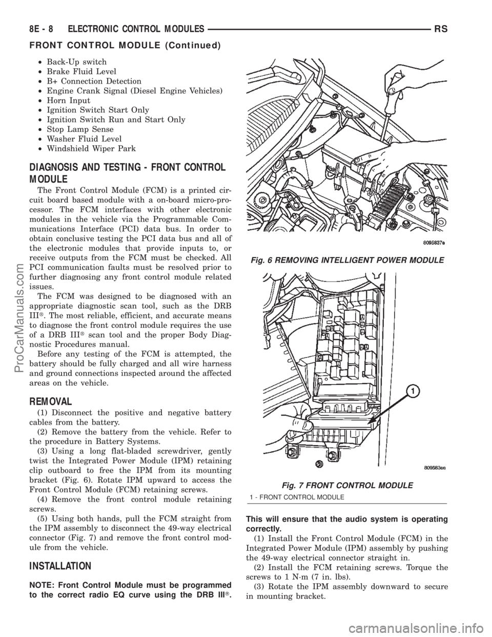
(3) Using a long flat-bladed screwdriver, gently
twist the Integrated Power Module (IPM) retaining
clip outboard to free the IPM from its mounting
bracket (Fig. 6). Rotate IPM upward to access the
Front Control Module (FCM) retaining screws.
(4) Remove the front control module retaining
screws.
(5) Using both hands, pull the FCM straight from
the IPM assembly to disconnect the 49-way electrical
connector (Fig. 7) and remove the front control mod-
ule from the vehicle.
INSTALLATION
NOTE: Front Control Module must be programmed
to the correct radio EQ curve using the DRB IIIT.This will ensure that the audio system is operating
correctly.
(1) Install the Front Control Module (FCM) in the
Integrated Power Module (IPM) assembly by pushing
the 49-way electrical connector straight in.
(2) Install the FCM retaining screws. Torque the
screws to 1 N´m (7 in. lbs).
(3) Rotate the IPM assembly downward to secure
in mounting bracket.
Fig. 6 REMOVING INTELLIGENT POWER MODULE
Fig. 7 FRONT CONTROL MODULE
1 - FRONT CONTROL MODULE
8E - 8 ELECTRONIC CONTROL MODULESRS
FRONT CONTROL MODULE (Continued)
ProCarManuals.com
Page 351 of 2399

(M) Check Engine Lamp (MIL) will illuminate during engine operation if this Diagnostic Trouble Code was recorded.
(G) Generator Lamp Illuminated
GENERIC
SCAN TOOL
CODEDRB SCAN TOOL DISPLAY DESCRIPTION OF DIAGNOSTIC TROUBLE CODE
P0106 (M) Barometric Pressure Out of Range MAP sensor input voltage out of an acceptable range
detected during reading of barometric pressure at key-on.
P0107 (M) Map Sensor Voltage Too Low MAP sensor input below minimum acceptable voltage.
P0108 (M) Map Sensor Voltage Too High MAP sensor input above maximum acceptable voltage.
P0110 Intake Air Temp Sensor Stuck A rationality error has been detected for the intake air temp.
sensor.
P0111 (M) Intake Air Temp Sensor Performance Intake Air change less than 3É C in 200 Miles
P0112 (M) Intake Air Temp Sensor Voltage Low Intake air (charge) temperature sensor input below the
minimum acceptable voltage.
P0113 (M) Intake Air Temp Sensor Voltage High Intake air (charge) temperature sensor input above the
maximum acceptable voltage.
P0116 Engine Coolant Temp Performance A rationality error has been detected in the coolant temp
sensor.
P0117 (M) ECT Sensor Voltage Too Low Engine coolant temperature sensor input below the minimum
acceptable voltage.
P0118 (M) ECT Sensor Voltage Too High Engine coolant temperature sensor input above the
maximum acceptable voltage.
P0121 (M) TPS Voltage Does Not Agree With
MAPTPS signal does not correlate to MAP sensor signal.
P0122 (M) Throttle Position Sensor Voltage Low Throttle position sensor input below the acceptable voltage
range.
P0123 (M) Throttle Position Sensor Voltage High Throttle position sensor input above the maximum
acceptable voltage.
P0125 (M) Engine Coolant Temp Not Reached Time to enter Closed Loop Operation (Fuel Control) is
excessive.
P0128 Thermostat Rationality A rationality error has been detected for the thermostat
P0129 Barometic Pressure Out-of-Range low MAP sensor input voltage out of an acceptable range
detected during reading of barometric pressure.
P0130 1/1 O2 Sensor Heater Relay Circuit An open or shorted condition detected in the ASD or CNG
shutoff relay control ckt.
P0131 (M) 1/1 O2 Sensor Shorted To Ground Oxygen sensor input voltage maintained below normal
operating range.
P0132 (M) 1/1 O2 Sensor Shorted To Voltage Oxygen sensor input voltage maintained above normal
operating range.
P0133 (M) 1/1 O2 Sensor Slow Response Oxygen sensor response slower than minimum required
switching frequency.
P0134 (M) 1/1 O2 Sensor Stays at Center Neither rich or lean condition is detected from the oxygen
sensor input.
P0135 (M) 1/1 O2 Sensor Heater Failure Oxygen sensor heater element malfunction.
P0136 1/2 O2 Sensor Heater Relay Circuit An open or shorted condition detected in the ASD or CNG
shutoff relay control ckt.
P0137 (M) 1/2 O2 Sensor Shorted To Ground Oxygen sensor input voltage maintained below normal
operating range.
8E - 14 ELECTRONIC CONTROL MODULESRS
POWERTRAIN CONTROL MODULE (Continued)
ProCarManuals.com