Engine ground CHRYSLER TOWN AND COUNTRY 2002 Workshop Manual
[x] Cancel search | Manufacturer: CHRYSLER, Model Year: 2002, Model line: TOWN AND COUNTRY, Model: CHRYSLER TOWN AND COUNTRY 2002Pages: 2399, PDF Size: 57.96 MB
Page 434 of 2399

BATTERY TEMPERATURE
SENSOR
DESCRIPTION
The PCM incorporates a Battery Temperature Sen-
sor (BTS) on its circuit board.
OPERATION
The PCM uses the temperature of the battery area
to control the charge system voltage. This tempera-
ture, along with data from monitored line voltage, is
used by the PCM to vary the battery charging rate.
The system voltage is higher at cold temperatures
and is gradually reduced as temperature around the
battery increases.
The ambient temperature sensor is used to control
the battery voltage based upon ambient temperature
(approximation of battery temperature). The PCM
maintains the optimal output of the generator by
monitoring battery voltage and controlling it to a
range of 13.5 - 14.7 volts based on battery tempera-
ture.
The battery temperature sensor is also used for
OBD II diagnostics. Certain faults and OBD II mon-
itors are either enabled or disabled depending upon
the battery temperature sensor input (example: dis-
able purge and EGR, enable LDP). Most OBD II
monitors are disabled below 20ÉF.
REMOVAL
The battery temperature sensor is not serviced sep-
arately. If replacement is necessary, the PCM must
be replaced.
GENERATOR
DESCRIPTION
The generator is belt-driven by the engine. It is
serviced only as a complete assembly. The generator
produces DC voltage at the B+ terminal. If the gen-
erator is failed, the generator assembly subcompo-
nents (generator and decoupler pulley) must be
inspected for individual failure and replaced accord-
ingly.
OPERATION
As the energized rotor begins to rotate within the
generator, the spinning magnetic field induces a cur-
rent into the windings of the stator coil. Once the
generator begins producing sufficient current, it also
provides the current needed to energize the rotor.
The Y type stator winding connections deliver the
induced AC current to 3 positive and 3 negative
diodes for rectification. From the diodes, rectified DC
current is delivered to the vehicles electrical system
through the generator, battery, and ground terminals.
Excessive or abnormal noise emitting from the gen-
erator may be caused by:
²Worn, loose or defective bearings
²Loose or defective drive pulley (2.4L) or decou-
pler (3.3/3.8L)
²Incorrect, worn, damaged or misadjusted drive
belt
²Loose mounting bolts
²Misaligned drive pulley
²Defective stator or diode
²Damaged internal fins
REMOVAL
REMOVAL - 2.4L
(1) Release hood latch and open hood.
(2) Disconnect battery negative cable.
(3) Disconnect the Inlet Air Temperature sensor.
(4) Remove the Air Box, refer to the Engine/Air
Cleaner for more information.
(5) Remove the EVAP Purge solenoid from its
bracket and reposition.
(6) Disconnect the push-in field wire connector
from back of generator.
(7) Remove nut holding B+ wire terminal to back
of generator.
(8) Separate B+ terminal from generator.
(9) Remove accessory drive belt, refer to the Cool-
ing System section for proper procedures.
(10) Remove the generator.
RGCHARGING8Fa-23
ProCarManuals.com
Page 441 of 2399

INSTALLATION
(1) Install the Generator Decoupler to the genera-
tor shaft.
(2) Use Special Tool #8433 (Fig. 20) to tighten the
Generator Decoupler (Fig. 21). Refer to the torque
chart for the proper torque.
(3) Install the Air Box, refer to the Engine section
for more information.
(4) Raise vehicle and support.
(5) Install accessory drive belt, refer to the Cooling
System section for proper procedures (Fig. 18).
(6) Install the right front lower splash shield.
(7) Lower vehicle.
(8) Connect battery negative cable.
VOLTAGE REGULATOR
DESCRIPTION
The Electronic Voltage Regulator (EVR) is not a
separate component. It is actually a voltage regulat-
ing circuit located within the Powertrain Control
Module (PCM). The EVR is not serviced separately. If
replacement is necessary, the PCM must be replaced.
OPERATION
The amount of DC current produced by the gener-
ator is controlled by EVR circuitry contained within
the PCM. This circuitry is connected in series with
the generators second rotor field terminal and its
ground.
Voltage is regulated by cycling the ground path to
control the strength of the rotor magnetic field. The
EVR circuitry monitors system line voltage (B+) and
calculated battery temperature or inlet air tempera-
ture sensor (refer to Inlet Air Temperature Sensor, if
equipped, for more information ). It then determines
a target charging voltage. If sensed battery voltage is
lower than the target voltage, the PCM grounds the
field winding until sensed battery voltage is at the
target voltage. A circuit in the PCM cycles the
ground side of the generator field at 250 times per
second (250Hz), but has the capability to ground the
field control wire 100% of the time (full field) to
achieve the target voltage. If the charging rate can-
not be monitored (limp-in), a duty cycle of 25% is
used by the PCM in order to have some generator
output. Also refer to Charging System Operation for
additional information.
Fig. 21 DECOUPLER INSTALLATION (Litens)
8Fa - 30 CHARGINGRG
GENERATOR DECOUPLER PULLEY (Continued)
ProCarManuals.com
Page 443 of 2399

INSPECTION
Before removing any unit from the starting system
for repair or diagnosis, perform the following inspec-
tions:
²Battery- Visually inspect the battery for indi-
cations of physical damage and loose or corroded
cable connections. Determine the state-of-charge and
cranking capacity of the battery. Charge or replace
the battery, if required. Refer to the Battery section
for more information.
²Ignition Switch- Visually inspect the ignition
switch for indications of physical damage and loose
or corroded wire harness connections.
²Transmission Range Sensor- Visually inspect
the transmission range sensor for indications of phys-
ical damage and loose or corroded wire harness con-
nections.
²Starter Relay- Visually inspect the starter
relay for indications of physical damage and loose or
corroded wire harness connections.
²Starter- Visually inspect the starter for indica-
tions of physical damage and loose or corroded wire
harness connections.
²Starter Solenoid- Visually inspect the starter
solenoid for indications of physical damage and loose
or corroded wire harness connections.
²Wiring- Visually inspect the wire harness for
damage. Repair or replace any faulty wiring, as
required. Check for loose or corroded wire harness
connections at main engine ground and remote jump
post.
²Power Distribution Center (PDC)- Visually
inspect the B+ connections at the PDC for physical
damage and loose or corroded harness connections.
Fig. 1 STARTING SYSTEM SCHEMATIC
1 - SOLENOID TERMINAL
2 - STARTER SOLENOID
3 - STARTER MOTOR
4 - STARTER RELAY CONNECTOR
5 - PCM
6 - GROUND CIRCUIT
7 - TRANSMISSION RANGE SENSOR/PARK/NEUTRAL SENSE
8 - IGNITION SWITCH
9 - IGNITION FEED
10 - BATTERY
11 - BATTERY RELAY FEED
12 - POSITIVE CABLE
13 - NEGATIVE CABLE
14 - CLUTCH INTERLOCK SWITCH (MTX ONLY)
8Fa - 32 STARTINGRG
STARTING (Continued)
ProCarManuals.com
Page 444 of 2399
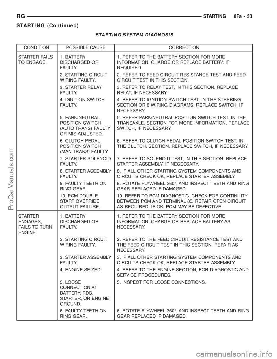
STARTING SYSTEM DIAGNOSIS
CONDITION POSSIBLE CAUSE CORRECTION
STARTER FAILS
TO ENGAGE.1. BATTERY
DISCHARGED OR
FAULTY.1. REFER TO THE BATTERY SECTION FOR MORE
INFORMATION. CHARGE OR REPLACE BATTERY, IF
REQUIRED.
2. STARTING CIRCUIT
WIRING FAULTY.2. REFER TO FEED CIRCUIT RESISTANCE TEST AND FEED
CIRCUIT TEST IN THIS SECTION.
3. STARTER RELAY
FAULTY.3. REFER TO RELAY TEST, IN THIS SECTION. REPLACE
RELAY, IF NECESSARY.
4. IGNITION SWITCH
FAULTY.4. REFER TO IGNITION SWITCH TEST, IN THE STEERING
SECTION OR 8 WIRING DIAGRAMS. REPLACE SWITCH, IF
NECESSARY.
5. PARK/NEUTRAL
POSITION SWITCH
(AUTO TRANS) FAULTY
OR MIS-ADJUSTED.5. REFER PARK/NEUTRAL POSITION SWITCH TEST, IN THE
TRANSAXLE. SECTION FOR MORE INFORMATION. REPLACE
SWITCH, IF NECESSARY.
6. CLUTCH PEDAL
POSITION SWITCH
(MAN TRANS) FAULTY.6. REFER TO CLUTCH PEDAL POSITION SWITCH TEST, IN
THE CLUTCH. SECTION. REPLACE SWITCH, IF NECESSARY.
7. STARTER SOLENOID
FAULTY.7. REFER TO SOLENOID TEST, IN THIS SECTION. REPLACE
STARTER ASSEMBLY, IF NECESSARY.
8. STARTER ASSEMBLY
FAULTY.8. IF ALL OTHER STARTING SYSTEM COMPONENTS AND
CIRCUITS CHECK OK, REPLACE STARTER ASSEMBLY.
9. FAULTY TEETH ON
RING GEAR.9. ROTATE FLYWHEEL 360É, AND INSPECT TEETH AND RING
GEAR REPLACED IF DAMAGED.
10. PCM DOUBLE
START OVERRIDE
OUTPUT FAILURE.10. REFER TO PCM DIAGNOSTIC. CHECK FOR CONTINUITY
BETWEEN PCM AND TERMINAL 85. REPAIR OPEN CIRCUIT
AS REQUIRED. IF OK, PCM MAY BE DEFECTIVE.
STARTER
ENGAGES,
FAILS TO TURN
ENGINE.1. BATTERY
DISCHARGED OR
FAULTY.1. REFER TO THE BATTERY SECTION FOR MORE
INFORMATION. CHARGE OR REPLACE BATTERY AS
NECESSARY.
2. STARTING CIRCUIT
WIRING FAULTY.2. REFER TO THE FEED CIRCUIT RESISTANCE TEST AND
THE FEED CIRCUIT TEST IN THIS SECTION. REPAIR AS
NECESSARY.
3. STARTER ASSEMBLY
FAULTY.3. IF ALL OTHER STARTING SYSTEM COMPONENTS AND
CIRCUITS CHECK OK, REPLACE STARTER ASSEMBLY.
4. ENGINE SEIZED. 4. REFER TO THE ENGINE SECTION, FOR DIAGNOSTIC AND
SERVICE PROCEDURES.
5. LOOSE
CONNECTION AT
BATTERY, PDC,
STARTER, OR ENGINE
GROUND.5. INSPECT FOR LOOSE CONNECTIONS.
6. FAULTY TEETH ON
RING GEAR.6. ROTATE FLYWHEEL 360É, AND INSPECT TEETH AND RING
GEAR REPLACED IF DAMAGED.
RGSTARTING8Fa-33
STARTING (Continued)
ProCarManuals.com
Page 446 of 2399
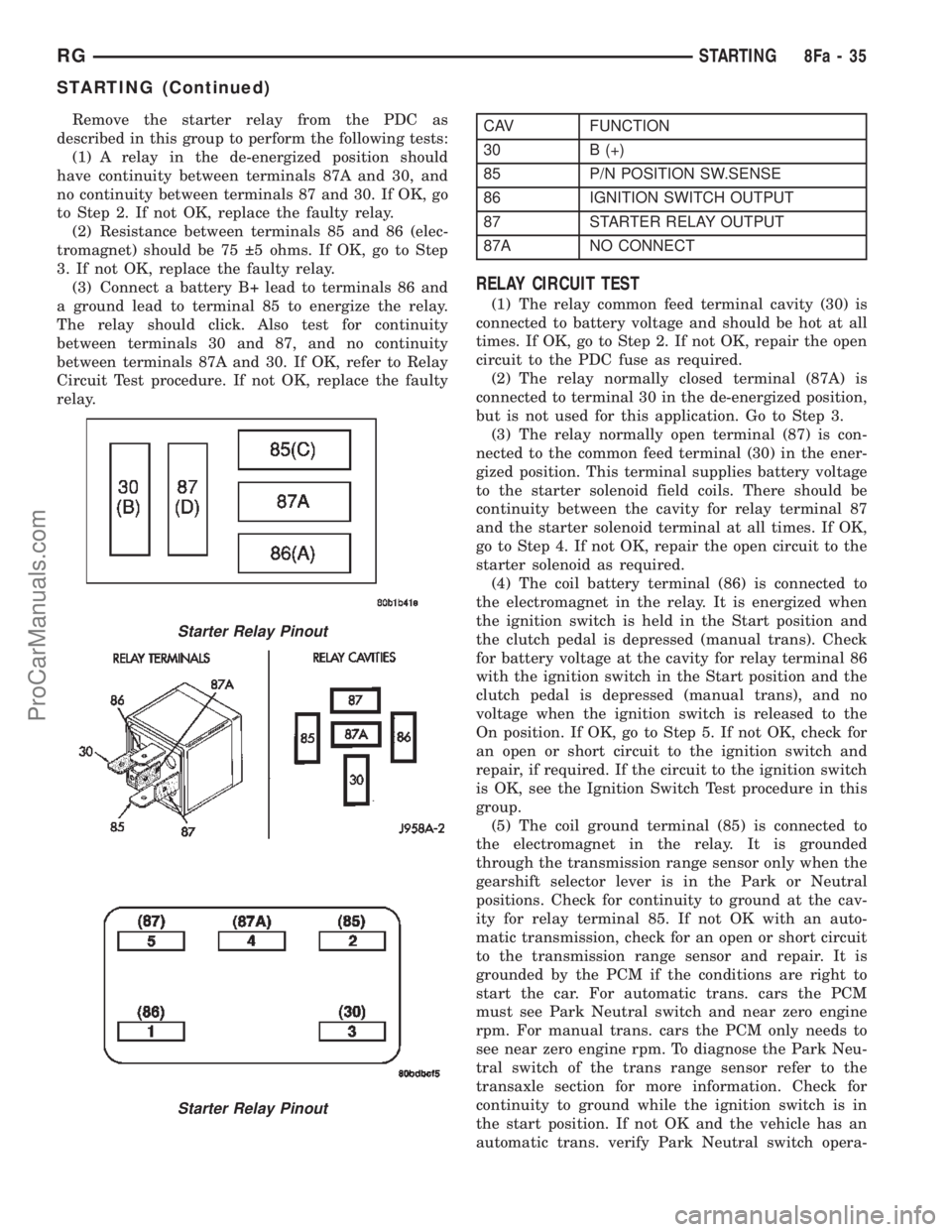
Remove the starter relay from the PDC as
described in this group to perform the following tests:
(1) A relay in the de-energized position should
have continuity between terminals 87A and 30, and
no continuity between terminals 87 and 30. If OK, go
to Step 2. If not OK, replace the faulty relay.
(2) Resistance between terminals 85 and 86 (elec-
tromagnet) should be 75 5 ohms. If OK, go to Step
3. If not OK, replace the faulty relay.
(3) Connect a battery B+ lead to terminals 86 and
a ground lead to terminal 85 to energize the relay.
The relay should click. Also test for continuity
between terminals 30 and 87, and no continuity
between terminals 87A and 30. If OK, refer to Relay
Circuit Test procedure. If not OK, replace the faulty
relay.CAV FUNCTION
30 B (+)
85 P/N POSITION SW.SENSE
86 IGNITION SWITCH OUTPUT
87 STARTER RELAY OUTPUT
87A NO CONNECT
RELAY CIRCUIT TEST
(1) The relay common feed terminal cavity (30) is
connected to battery voltage and should be hot at all
times. If OK, go to Step 2. If not OK, repair the open
circuit to the PDC fuse as required.
(2) The relay normally closed terminal (87A) is
connected to terminal 30 in the de-energized position,
but is not used for this application. Go to Step 3.
(3) The relay normally open terminal (87) is con-
nected to the common feed terminal (30) in the ener-
gized position. This terminal supplies battery voltage
to the starter solenoid field coils. There should be
continuity between the cavity for relay terminal 87
and the starter solenoid terminal at all times. If OK,
go to Step 4. If not OK, repair the open circuit to the
starter solenoid as required.
(4) The coil battery terminal (86) is connected to
the electromagnet in the relay. It is energized when
the ignition switch is held in the Start position and
the clutch pedal is depressed (manual trans). Check
for battery voltage at the cavity for relay terminal 86
with the ignition switch in the Start position and the
clutch pedal is depressed (manual trans), and no
voltage when the ignition switch is released to the
On position. If OK, go to Step 5. If not OK, check for
an open or short circuit to the ignition switch and
repair, if required. If the circuit to the ignition switch
is OK, see the Ignition Switch Test procedure in this
group.
(5) The coil ground terminal (85) is connected to
the electromagnet in the relay. It is grounded
through the transmission range sensor only when the
gearshift selector lever is in the Park or Neutral
positions. Check for continuity to ground at the cav-
ity for relay terminal 85. If not OK with an auto-
matic transmission, check for an open or short circuit
to the transmission range sensor and repair. It is
grounded by the PCM if the conditions are right to
start the car. For automatic trans. cars the PCM
must see Park Neutral switch and near zero engine
rpm. For manual trans. cars the PCM only needs to
see near zero engine rpm. To diagnose the Park Neu-
tral switch of the trans range sensor refer to the
transaxle section for more information. Check for
continuity to ground while the ignition switch is in
the start position. If not OK and the vehicle has an
automatic trans. verify Park Neutral switch opera-
Starter Relay Pinout
Starter Relay Pinout
RGSTARTING8Fa-35
STARTING (Continued)
ProCarManuals.com
Page 447 of 2399
tion. If that checks OK check for continuity between
PCM and the terminal 85. Repair open circuit as
required. If OK, the PCM may be defective.
SAFETY SWITCHES
For diagnostics of the Transmission Range Sensor,
refer to the Transaxle section for more information.
If equipped with Clutch Interlock/Upstop Switch,
refer to Diagnosis and Testing in the Clutch section.
IGNITION SWITCH
After testing starter solenoid and relay, test igni-
tion switch and wiring. Refer to the Ignition Section
or Wiring Diagrams for more information. Check all
wiring for opens or shorts, and all connectors for
being loose or corroded.
BATTERY
For battery diagnosis and testing, refer to the Bat-
tery section for procedures.
ALL RELATED WIRING AND CONNECTORS
Refer to Wiring Diagrams for more information.
DIAGNOSIS AND TESTING - FEED CIRCUIT
RESISTANCE TEST
Before proceeding with this operation, review Diag-
nostic Preparation and Starter Feed Circuit Tests.
The following operation will require a voltmeter,
accurate to 1/10 of a volt.
CAUTION: Ignition and Fuel systems must be dis-
abled to prevent engine start while performing the
following tests.
(1) To disable the Ignition and Fuel systems, dis-
connect the Automatic Shutdown Relay (ASD). The
ASD relay is located in the Power Distribution Cen-
ter (PDC). Refer to the PDC cover for proper relay
location.
(2) Gain access to battery terminals.
(3) With all wiring harnesses and components
properly connected, perform the following:
(a) Connect the negative lead of the voltmeter to
the battery negative post, and positive lead to the
battery negative cable clamp. Rotate and hold the
ignition switch in the START position. Observe the
voltmeter. If voltage is detected, correct poor con-
tact between cable clamp and post.
(b) Connect positive lead of the voltmeter to the
battery positive post, and negative lead to the bat-
tery positive cable clamp. Rotate and hold the igni-
tion switch key in the START position. Observe the
voltmeter. If voltage is detected, correct poor con-
tact between the cable clamp and post.(c) Connect negative lead of voltmeter to battery
negative terminal, and positive lead to engine
block near the battery cable attaching point.
Rotate and hold the ignition switch in the START
position. If voltage reads above 0.2 volt, correct
poor contact at ground cable attaching point. If
voltage reading is still above 0.2 volt after correct-
ing poor contacts, replace ground cable.
(4) Connect positive voltmeter lead to the starter
motor housing and the negative lead to the battery
negative terminal. Hold the ignition switch key in
the START position. If voltage reads above 0.2 volt,
correct poor starter to engine ground.
(a) Connect the positive voltmeter lead to the
battery positive terminal, and negative lead to bat-
tery cable terminal on starter solenoid. Rotate and
hold the ignition switch in the START position. If
voltage reads above 0.2 volt, correct poor contact at
battery cable to solenoid connection. If reading is
still above 0.2 volt after correcting poor contacts,
replace battery positive cable.
(b) If resistance tests do not detect feed circuit
failures, replace the starter motor.
DIAGNOSIS AND TESTING - FEED CIRCUIT
TEST
NOTE: The following results are based upon the
vehicle being at room temperature.
The following procedure will require a suitable
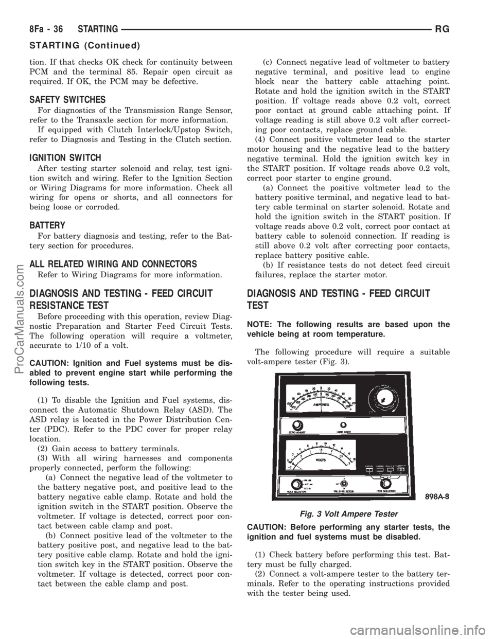
volt-ampere tester (Fig. 3).
CAUTION: Before performing any starter tests, the
ignition and fuel systems must be disabled.
(1) Check battery before performing this test. Bat-
tery must be fully charged.
(2) Connect a volt-ampere tester to the battery ter-
minals. Refer to the operating instructions provided
with the tester being used.
Fig. 3 Volt Ampere Tester
8Fa - 36 STARTINGRG
STARTING (Continued)
ProCarManuals.com
Page 451 of 2399
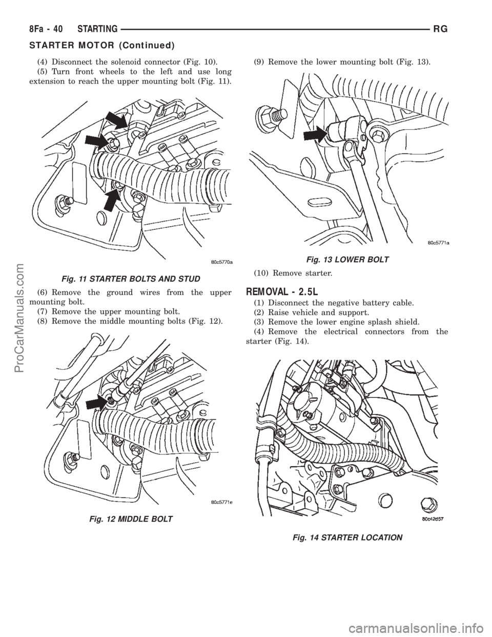
(4) Disconnect the solenoid connector (Fig. 10).
(5) Turn front wheels to the left and use long
extension to reach the upper mounting bolt (Fig. 11).
(6) Remove the ground wires from the upper
mounting bolt.
(7) Remove the upper mounting bolt.
(8) Remove the middle mounting bolts (Fig. 12).(9) Remove the lower mounting bolt (Fig. 13).
(10) Remove starter.
REMOVAL - 2.5L
(1) Disconnect the negative battery cable.
(2) Raise vehicle and support.
(3) Remove the lower engine splash shield.
(4) Remove the electrical connectors from the
starter (Fig. 14).
Fig. 11 STARTER BOLTS AND STUD
Fig. 12 MIDDLE BOLT
Fig. 13 LOWER BOLT
Fig. 14 STARTER LOCATION
8Fa - 40 STARTINGRG
STARTER MOTOR (Continued)
ProCarManuals.com
Page 452 of 2399
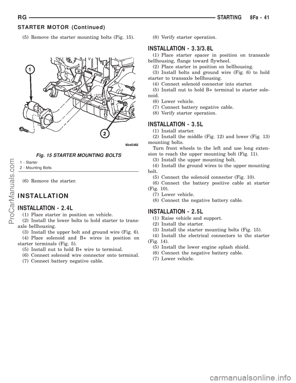
(5) Remove the starter mounting bolts (Fig. 15).
(6) Remove the starter.
INSTALLATION
INSTALLATION - 2.4L
(1) Place starter in position on vehicle.
(2) Install the lower bolts to hold starter to trans-
axle bellhousing.
(3) Install the upper bolt and ground wire (Fig. 6).
(4) Place solenoid and B+ wires in position on
starter terminals (Fig. 5).
(5) Install nut to hold B+ wire to terminal.
(6) Connect solenoid wire connector onto terminal.
(7) Connect battery negative cable.(8) Verify starter operation.
INSTALLATION - 3.3/3.8L
(1) Place starter spacer in position on transaxle
bellhousing, flange toward flywheel.
(2) Place starter in position on bellhousing.
(3) Install bolts and ground wire (Fig. 6) to hold
starter to transaxle bellhousing.
(4) Connect solenoid connector into starter.
(5) Install nut to hold B+ terminal to starter sole-
noid.
(6) Lower vehicle.
(7) Connect battery negative cable.
(8) Verify starter operation.
INSTALLATION - 3.5L
(1) Install starter.
(2) Install the middle (Fig. 12) and lower (Fig. 13)
mounting bolts.
Turn front wheels to the left and use long exten-
sion to reach the upper mounting bolt (Fig. 11).
(3) Install the upper mounting bolt.
(4) Install the ground wires to the upper mounting
bolt.
(5) Connect the solenoid connector (Fig. 10).
(6) Connect the battery positive cable at starter
(Fig. 10).
(7) Lower vehicle.
(8) Connect the negative battery cable.
INSTALLATION - 2.5L
(1) Raise vehicle and support.
(2) Install the starter.
(3) Install the starter mounting bolts (Fig. 15).
(4) Install the electrical connectors to the starter
(Fig. 14).
(5) Install the lower engine splash shield.
(6) Connect the negative battery cable.
(7) Lower vehicle.
Fig. 15 STARTER MOUNTING BOLTS
1 - Starter
2 - Mounting Bolts
RGSTARTING8Fa-41
STARTER MOTOR (Continued)
ProCarManuals.com
Page 470 of 2399
HORN
TABLE OF CONTENTS
page page
HORN SYSTEM
DESCRIPTION..........................1
OPERATION............................1
DIAGNOSIS AND TESTING - HORN SYSTEM . . . 1
HORN
DIAGNOSIS AND TESTING - HORN..........3
REMOVAL.............................4INSTALLATION..........................4
HORN RELAY
DIAGNOSIS AND TESTING - HORN RELAY....5
REMOVAL.............................5
INSTALLATION..........................5
HORN SWITCH
DESCRIPTION..........................5
HORN SYSTEM
DESCRIPTION
WARNING: ON VEHICLES EQUIPPED WITH AIR-
BAG, REFER TO ELECTRICAL, RESTRAINTS FOR
SAFETY PRECAUTIONS. DISCONNECT THE NEGA-
TIVE CABLE FROM THE BATTERY BEFORE SER-
VICING COMPONENTS INVOLVING THE AIRBAG
SYSTEM. ACCIDENTAL DEPLOYMENT OF AIRBAG
AND PERSONAL INJURY CAN RESULT.
The horn circuit consists of a horn switch, clock-
spring, horn relay, horns and Integrated Power Mod-
ule (IPM). The horn switch is a membrane switch
located in the airbag trim cover. The horns are
located forward of the left front wheel behind the
bumper fascia.
OPERATION
The horn relay plugs into the Integrated Power
Module (IPM) which is located in the engine com-
partment. For circuit information and component
locations, refer to the appropriate wiring information.
The wiring information includes wiring diagrams,
proper wire and connector repair procedures, details
of wire harness routing and retention, connector pin-
out information and location views for the various
wire harness connectors, splices and grounds.
The horns will not function if the switch is
ªCLOSEDº for more than 30 seconds. Once the
switch is ªOPENº, a 20±30 second delay will occur
before the horns are functional again.
DIAGNOSIS AND TESTING - HORN SYSTEM
WARNING: ON VEHICLES EQUIPPED WITH AIR-
BAGS, REFER TO ELECTRICAL, RESTRAINTS
BEFORE ATTEMPTING ANY STEERING WHEEL,
STEERING COLUMN, OR INSTRUMENT PANEL
COMPONENT DIAGNOSIS OR SERVICE. FAILURE
TO TAKE THE PROPER PRECAUTIONS COULD
RESULT IN ACCIDENTAL AIRBAG DEPLOYMENT
AND POSSIBLE PERSONAL INJURY.
Refer to Horn System Test below. If the horn does
not sound, check horn fuse located in the Integrated
Power Module (IPM). If the fuse is blown, replace
with the correct fuse. If the horns fail to sound and
the new fuse blows when depressing the horn switch,
a short circuit in the horn or the horn wiring
between the fuse terminal and the horn is responsi-
ble, or a defective horn switch allowed the horn to
burn out is responsible.
If the fuse is OK, test horn relay (Refer to 8 -
ELECTRICAL/HORN/HORN RELAY - DIAGNOSIS
AND TESTING).
If the relay is OK, test horn. Refer to Horn System
Test.
CAUTION: Continuous sounding of horn may
cause horn failure.
Should the horn sound continuously:
²Unplug the horn relay from IPM.
²Refer to (Refer to 8 - ELECTRICAL/HORN/
HORN RELAY - DIAGNOSIS AND TESTING).
Refer to the appropriate wiring information. The
wiring information includes wiring diagrams, proper
wire and connector repair procedures, details of wire
harness routing and retention, connector pin-out
information and location views for the various wire
harness connectors, splices and grounds.
RSHORN8H-1
ProCarManuals.com
Page 478 of 2399
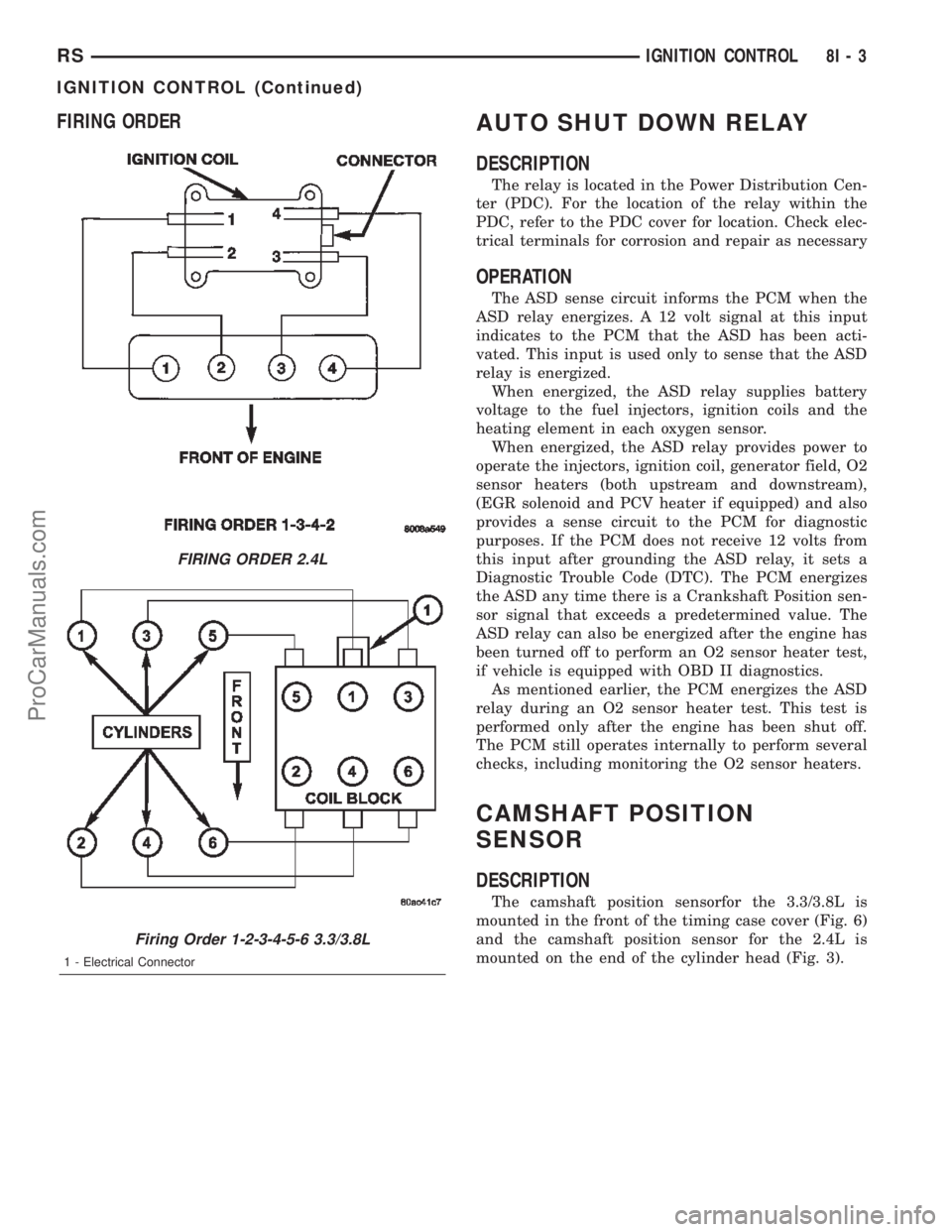
FIRING ORDERAUTO SHUT DOWN RELAY
DESCRIPTION
The relay is located in the Power Distribution Cen-
ter (PDC). For the location of the relay within the
PDC, refer to the PDC cover for location. Check elec-
trical terminals for corrosion and repair as necessary
OPERATION
The ASD sense circuit informs the PCM when the
ASD relay energizes. A 12 volt signal at this input
indicates to the PCM that the ASD has been acti-
vated. This input is used only to sense that the ASD
relay is energized.
When energized, the ASD relay supplies battery
voltage to the fuel injectors, ignition coils and the
heating element in each oxygen sensor.
When energized, the ASD relay provides power to
operate the injectors, ignition coil, generator field, O2
sensor heaters (both upstream and downstream),
(EGR solenoid and PCV heater if equipped) and also
provides a sense circuit to the PCM for diagnostic
purposes. If the PCM does not receive 12 volts from
this input after grounding the ASD relay, it sets a
Diagnostic Trouble Code (DTC). The PCM energizes
the ASD any time there is a Crankshaft Position sen-
sor signal that exceeds a predetermined value. The
ASD relay can also be energized after the engine has
been turned off to perform an O2 sensor heater test,
if vehicle is equipped with OBD II diagnostics.
As mentioned earlier, the PCM energizes the ASD
relay during an O2 sensor heater test. This test is
performed only after the engine has been shut off.
The PCM still operates internally to perform several
checks, including monitoring the O2 sensor heaters.
CAMSHAFT POSITION
SENSOR
DESCRIPTION
The camshaft position sensorfor the 3.3/3.8L is
mounted in the front of the timing case cover (Fig. 6)
and the camshaft position sensor for the 2.4L is
mounted on the end of the cylinder head (Fig. 3).
FIRING ORDER 2.4L
Firing Order 1-2-3-4-5-6 3.3/3.8L
1 - Electrical Connector
RSIGNITION CONTROL8I-3
IGNITION CONTROL (Continued)
ProCarManuals.com