Engine ground CHRYSLER TOWN AND COUNTRY 2002 Owner's Guide
[x] Cancel search | Manufacturer: CHRYSLER, Model Year: 2002, Model line: TOWN AND COUNTRY, Model: CHRYSLER TOWN AND COUNTRY 2002Pages: 2399, PDF Size: 57.96 MB
Page 404 of 2399

²Starter- Visually inspect the starter for indica-
tions of physical damage and loose or corroded wire
harness connections.
²Starter Solenoid- Visually inspect the starter
solenoid for indications of physical damage and loose
or corroded wire harness connections.
²Wiring- Visually inspect the wire harness for
damage. Repair or replace any faulty wiring, as
required. Check for loose or corroded wire harness
connections at main engine ground and remote jump
post.
²Power Distribution Center (PDC)- Visually
inspect the B+ connections at the PDC for physical
damage and loose or corroded harness connections.
Fig. 1 STARTING SYSTEM SCHEMATIC
1 - SOLENOID TERMINAL
2 - STARTER SOLENOID
3 - STARTER MOTOR
4 - STARTER RELAY CONNECTOR
5 - PCM
6 - GROUND CIRCUIT
7 - TRANSMISSION RANGE SENSOR/PARK/NEUTRAL SENSE
8 - IGNITION SWITCH
9 - IGNITION FEED
10 - BATTERY
11 - BATTERY RELAY FEED
12 - POSITIVE CABLE
13 - NEGATIVE CABLE
14 - CLUTCH INTERLOCK SWITCH (MTX ONLY)
RSSTARTING8F-29
STARTING (Continued)
ProCarManuals.com
Page 405 of 2399
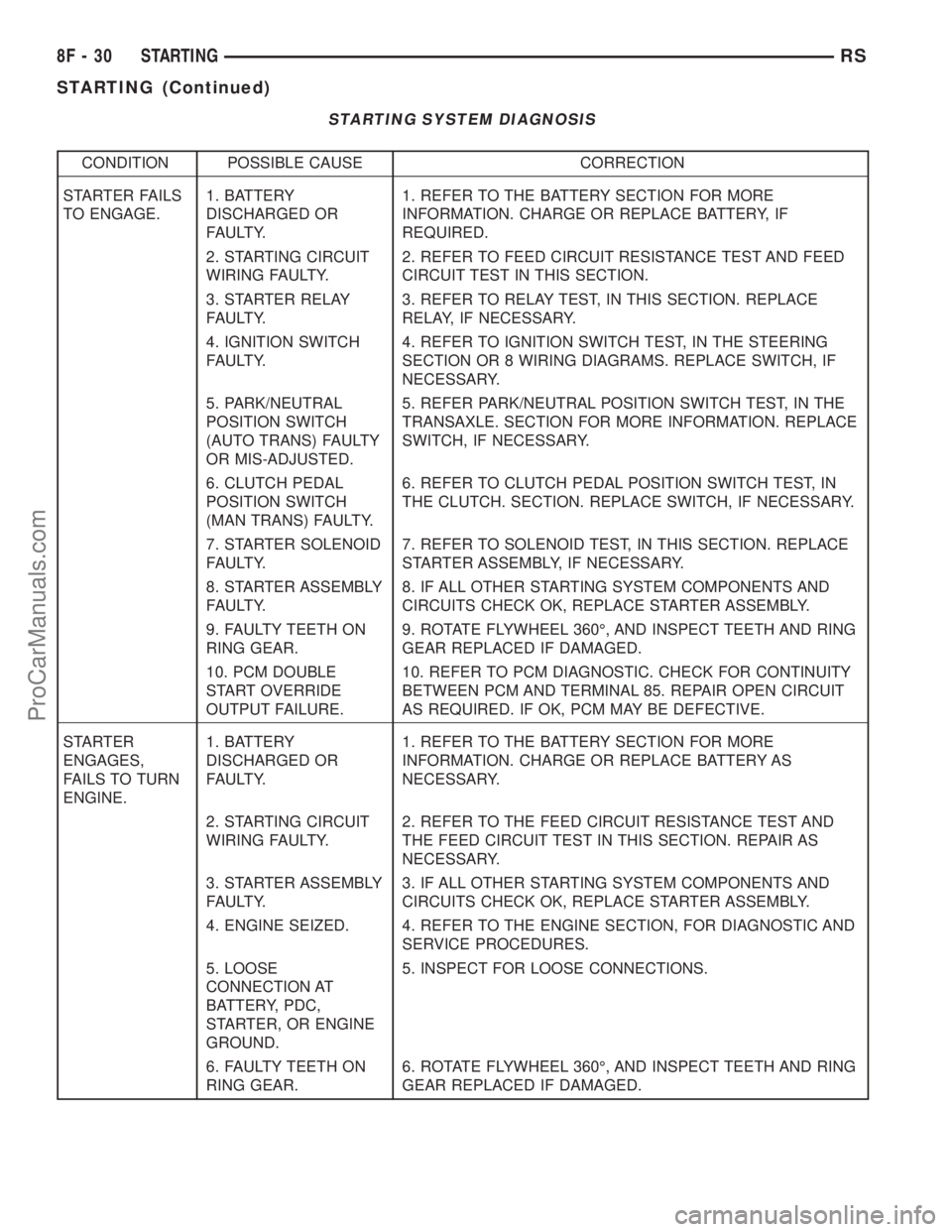
STARTING SYSTEM DIAGNOSIS
CONDITION POSSIBLE CAUSE CORRECTION
STARTER FAILS
TO ENGAGE.1. BATTERY
DISCHARGED OR
FAULTY.1. REFER TO THE BATTERY SECTION FOR MORE
INFORMATION. CHARGE OR REPLACE BATTERY, IF
REQUIRED.
2. STARTING CIRCUIT
WIRING FAULTY.2. REFER TO FEED CIRCUIT RESISTANCE TEST AND FEED
CIRCUIT TEST IN THIS SECTION.
3. STARTER RELAY
FAULTY.3. REFER TO RELAY TEST, IN THIS SECTION. REPLACE
RELAY, IF NECESSARY.
4. IGNITION SWITCH
FAULTY.4. REFER TO IGNITION SWITCH TEST, IN THE STEERING
SECTION OR 8 WIRING DIAGRAMS. REPLACE SWITCH, IF
NECESSARY.
5. PARK/NEUTRAL
POSITION SWITCH
(AUTO TRANS) FAULTY
OR MIS-ADJUSTED.5. REFER PARK/NEUTRAL POSITION SWITCH TEST, IN THE
TRANSAXLE. SECTION FOR MORE INFORMATION. REPLACE
SWITCH, IF NECESSARY.
6. CLUTCH PEDAL
POSITION SWITCH
(MAN TRANS) FAULTY.6. REFER TO CLUTCH PEDAL POSITION SWITCH TEST, IN
THE CLUTCH. SECTION. REPLACE SWITCH, IF NECESSARY.
7. STARTER SOLENOID
FAULTY.7. REFER TO SOLENOID TEST, IN THIS SECTION. REPLACE
STARTER ASSEMBLY, IF NECESSARY.
8. STARTER ASSEMBLY
FAULTY.8. IF ALL OTHER STARTING SYSTEM COMPONENTS AND
CIRCUITS CHECK OK, REPLACE STARTER ASSEMBLY.
9. FAULTY TEETH ON
RING GEAR.9. ROTATE FLYWHEEL 360É, AND INSPECT TEETH AND RING
GEAR REPLACED IF DAMAGED.
10. PCM DOUBLE
START OVERRIDE
OUTPUT FAILURE.10. REFER TO PCM DIAGNOSTIC. CHECK FOR CONTINUITY
BETWEEN PCM AND TERMINAL 85. REPAIR OPEN CIRCUIT
AS REQUIRED. IF OK, PCM MAY BE DEFECTIVE.
STARTER
ENGAGES,
FAILS TO TURN
ENGINE.1. BATTERY
DISCHARGED OR
FAULTY.1. REFER TO THE BATTERY SECTION FOR MORE
INFORMATION. CHARGE OR REPLACE BATTERY AS
NECESSARY.
2. STARTING CIRCUIT
WIRING FAULTY.2. REFER TO THE FEED CIRCUIT RESISTANCE TEST AND
THE FEED CIRCUIT TEST IN THIS SECTION. REPAIR AS
NECESSARY.
3. STARTER ASSEMBLY
FAULTY.3. IF ALL OTHER STARTING SYSTEM COMPONENTS AND
CIRCUITS CHECK OK, REPLACE STARTER ASSEMBLY.
4. ENGINE SEIZED. 4. REFER TO THE ENGINE SECTION, FOR DIAGNOSTIC AND
SERVICE PROCEDURES.
5. LOOSE
CONNECTION AT
BATTERY, PDC,
STARTER, OR ENGINE
GROUND.5. INSPECT FOR LOOSE CONNECTIONS.
6. FAULTY TEETH ON
RING GEAR.6. ROTATE FLYWHEEL 360É, AND INSPECT TEETH AND RING
GEAR REPLACED IF DAMAGED.
8F - 30 STARTINGRS
STARTING (Continued)
ProCarManuals.com
Page 407 of 2399

Remove the starter relay from the PDC as
described in this group to perform the following tests:
(1) A relay in the de-energized position should
have continuity between terminals 87A and 30, and
no continuity between terminals 87 and 30. If OK, go
to Step 2. If not OK, replace the faulty relay.
(2) Resistance between terminals 85 and 86 (elec-
tromagnet) should be 75 5 ohms. If OK, go to Step
3. If not OK, replace the faulty relay.
(3) Connect a battery B+ lead to terminals 86 and
a ground lead to terminal 85 to energize the relay.
The relay should click. Also test for continuity
between terminals 30 and 87, and no continuity
between terminals 87A and 30. If OK, refer to Relay
Circuit Test procedure. If not OK, replace the faulty
relay.CAV FUNCTION
30 B (+)
85 P/N POSITION SW.SENSE
86 IGNITION SWITCH OUTPUT
87 STARTER RELAY OUTPUT
87A NO CONNECT
RELAY CIRCUIT TEST
(1) The relay common feed terminal cavity (30) is
connected to battery voltage and should be hot at all
times. If OK, go to Step 2. If not OK, repair the open
circuit to the PDC fuse as required.
(2) The relay normally closed terminal (87A) is
connected to terminal 30 in the de-energized position,
but is not used for this application. Go to Step 3.
(3) The relay normally open terminal (87) is con-
nected to the common feed terminal (30) in the ener-
gized position. This terminal supplies battery voltage
to the starter solenoid field coils. There should be
continuity between the cavity for relay terminal 87
and the starter solenoid terminal at all times. If OK,
go to Step 4. If not OK, repair the open circuit to the
starter solenoid as required.
(4) The coil battery terminal (86) is connected to
the electromagnet in the relay. It is energized when
the ignition switch is held in the Start position and
the clutch pedal is depressed (manual trans). Check
for battery voltage at the cavity for relay terminal 86
with the ignition switch in the Start position and the
clutch pedal is depressed (manual trans), and no
voltage when the ignition switch is released to the
On position. If OK, go to Step 5. If not OK, check for
an open or short circuit to the ignition switch and
repair, if required. If the circuit to the ignition switch
is OK, see the Ignition Switch Test procedure in this
group.
(5) The coil ground terminal (85) is connected to
the electromagnet in the relay. It is grounded
through the transmission range sensor only when the
gearshift selector lever is in the Park or Neutral
positions. Check for continuity to ground at the cav-
ity for relay terminal 85. If not OK with an auto-
matic transmission, check for an open or short circuit
to the transmission range sensor and repair. It is
grounded by the PCM if the conditions are right to
start the car. For automatic trans. cars the PCM
must see Park Neutral switch and near zero engine
rpm. For manual trans. cars the PCM only needs to
see near zero engine rpm. To diagnose the Park Neu-
tral switch of the trans range sensor refer to the
transaxle section for more information. Check for
continuity to ground while the ignition switch is in
the start position. If not OK and the vehicle has an
automatic trans. verify Park Neutral switch opera-
Starter Relay Pinout
Starter Relay Pinout
8F - 32 STARTINGRS
STARTING (Continued)
ProCarManuals.com
Page 408 of 2399

tion. If that checks OK check for continuity between
PCM and the terminal 85. Repair open circuit as
required. If OK, the PCM may be defective.
SAFETY SWITCHES
For diagnostics of the Transmission Range Sensor,
refer to the Transaxle section for more information.
If equipped with Clutch Interlock/Upstop Switch,
refer to Diagnosis and Testing in the Clutch section.
IGNITION SWITCH
After testing starter solenoid and relay, test igni-
tion switch and wiring. Refer to the Ignition Section
or Wiring Diagrams for more information. Check all
wiring for opens or shorts, and all connectors for
being loose or corroded.
BATTERY
For battery diagnosis and testing, refer to the Bat-
tery section for procedures.
ALL RELATED WIRING AND CONNECTORS
Refer to Wiring Diagrams for more information.
DIAGNOSIS AND TESTING - FEED CIRCUIT
RESISTANCE TEST
Before proceeding with this operation, review Diag-
nostic Preparation and Starter Feed Circuit Tests.
The following operation will require a voltmeter,
accurate to 1/10 of a volt.
CAUTION: Ignition and Fuel systems must be dis-
abled to prevent engine start while performing the
following tests.
(1) To disable the Ignition and Fuel systems, dis-
connect the Automatic Shutdown Relay (ASD). The
ASD relay is located in the Power Distribution Cen-
ter (PDC). Refer to the PDC cover for proper relay
location.
(2) Gain access to battery terminals.
(3) With all wiring harnesses and components
properly connected, perform the following:
(a) Connect the negative lead of the voltmeter to
the battery negative post, and positive lead to the
battery negative cable clamp. Rotate and hold the
ignition switch in the START position. Observe the
voltmeter. If voltage is detected, correct poor con-
tact between cable clamp and post.
(b) Connect positive lead of the voltmeter to the
battery positive post, and negative lead to the bat-
tery positive cable clamp. Rotate and hold the igni-
tion switch key in the START position. Observe the
voltmeter. If voltage is detected, correct poor con-
tact between the cable clamp and post.(c) Connect negative lead of voltmeter to battery
negative terminal, and positive lead to engine
block near the battery cable attaching point.
Rotate and hold the ignition switch in the START
position. If voltage reads above 0.2 volt, correct
poor contact at ground cable attaching point. If
voltage reading is still above 0.2 volt after correct-
ing poor contacts, replace ground cable.
(4) Connect positive voltmeter lead to the starter
motor housing and the negative lead to the battery
negative terminal. Hold the ignition switch key in
the START position. If voltage reads above 0.2 volt,
correct poor starter to engine ground.
(a) Connect the positive voltmeter lead to the
battery positive terminal, and negative lead to bat-
tery cable terminal on starter solenoid. Rotate and
hold the ignition switch in the START position. If
voltage reads above 0.2 volt, correct poor contact at
battery cable to solenoid connection. If reading is
still above 0.2 volt after correcting poor contacts,
replace battery positive cable.
(b) If resistance tests do not detect feed circuit
failures, replace the starter motor.
DIAGNOSIS AND TESTING - FEED CIRCUIT
TEST
NOTE: The following results are based upon the
vehicle being at room temperature.
The following procedure will require a suitable
volt-ampere tester (Fig. 3).
CAUTION: Before performing any starter tests, the
ignition and fuel systems must be disabled.
(1) Check battery before performing this test. Bat-
tery must be fully charged.
(2) Connect a volt-ampere tester to the battery ter-
minals. Refer to the operating instructions provided
with the tester being used.
Fig. 3 Volt Ampere Tester
RSSTARTING8F-33
STARTING (Continued)
ProCarManuals.com
Page 411 of 2399
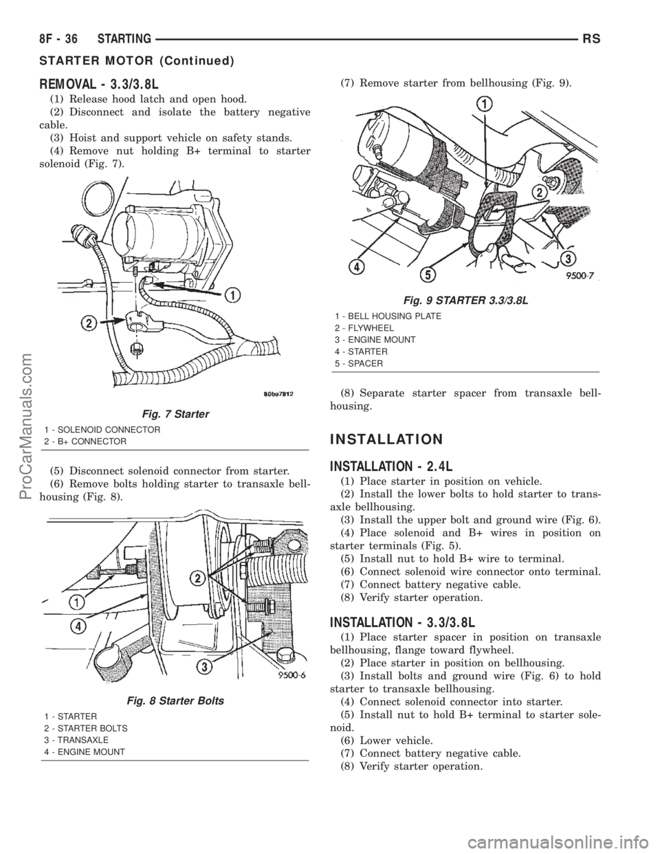
REMOVAL - 3.3/3.8L
(1) Release hood latch and open hood.
(2) Disconnect and isolate the battery negative
cable.
(3) Hoist and support vehicle on safety stands.
(4) Remove nut holding B+ terminal to starter
solenoid (Fig. 7).
(5) Disconnect solenoid connector from starter.
(6) Remove bolts holding starter to transaxle bell-
housing (Fig. 8).(7) Remove starter from bellhousing (Fig. 9).
(8) Separate starter spacer from transaxle bell-
housing.
INSTALLATION
INSTALLATION - 2.4L
(1) Place starter in position on vehicle.
(2) Install the lower bolts to hold starter to trans-
axle bellhousing.
(3) Install the upper bolt and ground wire (Fig. 6).
(4) Place solenoid and B+ wires in position on
starter terminals (Fig. 5).
(5) Install nut to hold B+ wire to terminal.
(6) Connect solenoid wire connector onto terminal.
(7) Connect battery negative cable.
(8) Verify starter operation.
INSTALLATION - 3.3/3.8L
(1) Place starter spacer in position on transaxle
bellhousing, flange toward flywheel.
(2) Place starter in position on bellhousing.
(3) Install bolts and ground wire (Fig. 6) to hold
starter to transaxle bellhousing.
(4) Connect solenoid connector into starter.
(5) Install nut to hold B+ terminal to starter sole-
noid.
(6) Lower vehicle.
(7) Connect battery negative cable.
(8) Verify starter operation.
Fig. 7 Starter
1 - SOLENOID CONNECTOR
2 - B+ CONNECTOR
Fig. 8 Starter Bolts
1-STARTER
2 - STARTER BOLTS
3 - TRANSAXLE
4 - ENGINE MOUNT
Fig. 9 STARTER 3.3/3.8L
1 - BELL HOUSING PLATE
2 - FLYWHEEL
3 - ENGINE MOUNT
4-STARTER
5 - SPACER
8F - 36 STARTINGRS
STARTER MOTOR (Continued)
ProCarManuals.com
Page 427 of 2399
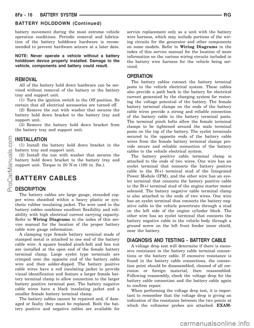
battery movement during the most extreme vehicle
operation conditions. Periodic removal and lubrica-
tion of the battery holddown hardware is recom-
mended to prevent hardware seizure at a later date.
NOTE: Never operate a vehicle without a battery
holddown device properly installed. Damage to the
vehicle, components and battery could result.
REMOVAL
All of the battery hold down hardware can be ser-
viced without removal of the battery or the battery
tray and support unit.
(1) Turn the ignition switch to the Off position. Be
certain that all electrical accessories are turned off.
(2) Remove the nut with washer that secures the
battery hold down bracket to the battery tray and
support unit.
(3) Remove the battery hold down bracket from
the battery tray and support unit.
INSTALLATION
(1) Install the battery hold down bracket in the
battery tray and support unit.
(2) Install the nut with washer that secures the
battery hold down bracket to the battery tray and
support unit. Torque to 20 N´m (180 in. lbs.).
BATTERY CABLES
DESCRIPTION
The battery cables are large gauge, stranded cop-
per wires sheathed within a heavy plastic or syn-
thetic rubber insulating jacket. The wire used in the
battery cables combines excellent flexibility and reli-
ability with high electrical current carrying capacity.
Refer toWiring Diagramsin the index of this ser-
vice manual for the location of the proper battery
cable wire gauge information.
A clamping type female battery terminal made of
stamped metal is attached to one end of the battery
cable wire. A square headed pinch-bolt and hex nut
are installed at the open end of the female battery
terminal clamp. Large eyelet type terminals are
crimped onto the opposite end of the battery cable
wire and then solder-dipped. The battery positive
cable wires have a red insulating jacket to provide
visual identification and feature a larger female bat-
tery terminal clamp to allow connection to the larger
battery positive terminal post. The battery negative
cable wires have a black insulating jacket and a
smaller female battery terminal clamp.
The battery cables cannot be repaired and, if dam-
aged or faulty they must be replaced. Both the bat-
tery positive and negative cables are available forservice replacement only as a unit with the battery
wire harness, which may include portions of the wir-
ing circuits for the generator and other components
on some models. Refer toWiring Diagramsin the
index of this service manual for the location of more
information on the various wiring circuits included in
the battery wire harness for the vehicle being ser-
viced.
OPERATION
The battery cables connect the battery terminal
posts to the vehicle electrical system. These cables
also provide a path back to the battery for electrical
current generated by the charging system for restor-
ing the voltage potential of the battery. The female
battery terminal clamps on the ends of the battery
cable wires provide a strong and reliable connection
of the battery cable to the battery terminal posts.
The terminal pinch bolts allow the female terminal
clamps to be tightened around the male terminal
posts on the top of the battery. The eyelet terminals
secured to the opposite ends of the battery cable
wires from the female battery terminal clamps pro-
vide secure and reliable connection of the battery
cables to the vehicle electrical system.
The battery positive cable terminal clamp is
attached to the ends of two wires. One wire has an
eyelet terminal that connects the battery positive
cable to the B(+) terminal stud of the Integrated
Power Module (IPM), and the other wire has an eye-
let terminal that connects the battery positive cable
to the B(+) terminal stud of the engine starter motor
solenoid. The battery negative cable terminal clamp
is also attached to the ends of two wires. One wire
has an eyelet terminal that connects the battery neg-
ative cable to the vehicle powertrain through a stud
on the left side of the engine cylinder block. The
other wire has an eyelet terminal that connects the
battery negative cable to the vehicle body through a
ground screw on the left front fender inner shield,
near the battery.
DIAGNOSIS AND TESTING - BATTERY CABLE
A voltage drop test will determine if there is exces-
sive resistance in the battery cable terminal connec-
tions or the battery cable. If excessive resistance is
found in the battery cable connections, the connec-
tion point should be disassembled, cleaned of all cor-
rosion or foreign material, then reassembled.
Following reassembly, check the voltage drop for the
battery cable connection and the battery cable again
to confirm repair.
When performing the voltage drop test, it is impor-
tant to remember that the voltage drop is giving an
indication of the resistance between the two points at
which the voltmeter probes are attached.EXAM-
8Fa - 16 BATTERY SYSTEMRG
BATTERY HOLDDOWN (Continued)
ProCarManuals.com
Page 428 of 2399
PLE:When testing the resistance of the battery pos-
itive cable, touch the voltmeter leads to the battery
positive cable terminal clamp and to the battery pos-
itive cable eyelet terminal at the starter solenoid
B(+) terminal stud. If you probe the battery positive
terminal post and the battery positive cable eyelet
terminal at the starter solenoid B(+) terminal stud,
you are reading the combined voltage drop in the
battery positive cable terminal clamp-to-terminal
post connection and the battery positive cable.
VOLTAGE DROP TEST
The following operation will require a voltmeter
accurate to 1/10 (0.10) volt. Before performing this
test, be certain that the following procedures are
accomplished:
²The battery is fully-charged and load tested.
Refer to Standard Procedures for the proper battery
charging and load test procedures.
²Fully engage the parking brake.
²If the vehicle is equipped with an automatic
transmission, place the gearshift selector lever in the
Park position. If the vehicle is equipped with a man-
ual transmission, place the gearshift selector lever in
the Neutral position and block the clutch pedal in the
fully depressed position.
²Verify that all lamps and accessories are turned
off.
²To prevent the engine from starting, remove the
Automatic Shut Down (ASD) relay. The ASD relay is
located in the Intelligent Power Module (IPM), in the
engine compartment. See the fuse and relay layout
label affixed to the underside of the IPM cover for
ASD relay identification and location.
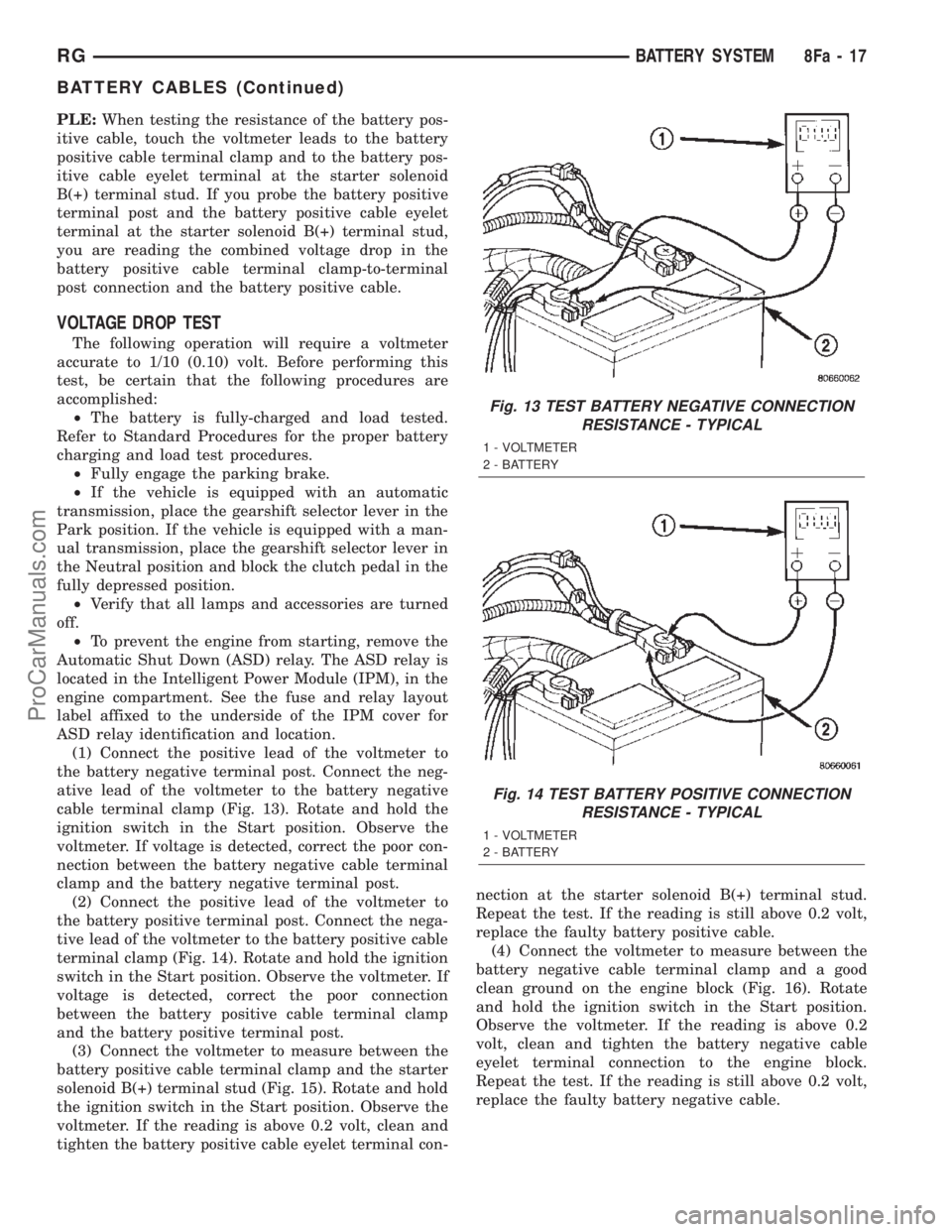
(1) Connect the positive lead of the voltmeter to
the battery negative terminal post. Connect the neg-
ative lead of the voltmeter to the battery negative
cable terminal clamp (Fig. 13). Rotate and hold the
ignition switch in the Start position. Observe the
voltmeter. If voltage is detected, correct the poor con-
nection between the battery negative cable terminal
clamp and the battery negative terminal post.
(2) Connect the positive lead of the voltmeter to
the battery positive terminal post. Connect the nega-
tive lead of the voltmeter to the battery positive cable
terminal clamp (Fig. 14). Rotate and hold the ignition
switch in the Start position. Observe the voltmeter. If
voltage is detected, correct the poor connection
between the battery positive cable terminal clamp
and the battery positive terminal post.
(3) Connect the voltmeter to measure between the
battery positive cable terminal clamp and the starter
solenoid B(+) terminal stud (Fig. 15). Rotate and hold
the ignition switch in the Start position. Observe the
voltmeter. If the reading is above 0.2 volt, clean and
tighten the battery positive cable eyelet terminal con-nection at the starter solenoid B(+) terminal stud.
Repeat the test. If the reading is still above 0.2 volt,
replace the faulty battery positive cable.
(4) Connect the voltmeter to measure between the
battery negative cable terminal clamp and a good
clean ground on the engine block (Fig. 16). Rotate
and hold the ignition switch in the Start position.
Observe the voltmeter. If the reading is above 0.2
volt, clean and tighten the battery negative cable
eyelet terminal connection to the engine block.
Repeat the test. If the reading is still above 0.2 volt,
replace the faulty battery negative cable.
Fig. 13 TEST BATTERY NEGATIVE CONNECTION
RESISTANCE - TYPICAL
1 - VOLTMETER
2 - BATTERY
Fig. 14 TEST BATTERY POSITIVE CONNECTION
RESISTANCE - TYPICAL
1 - VOLTMETER
2 - BATTERY
RGBATTERY SYSTEM8Fa-17
BATTERY CABLES (Continued)
ProCarManuals.com
Page 429 of 2399
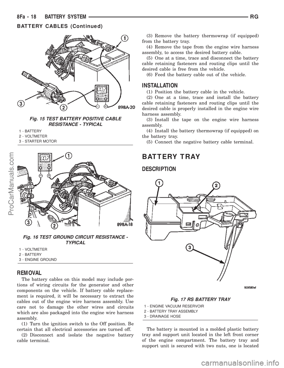
REMOVAL
The battery cables on this model may include por-
tions of wiring circuits for the generator and other
components on the vehicle. If battery cable replace-
ment is required, it will be necessary to extract the
cables out of the engine wire harness assembly. Use
care not to damage the other wires and circuits
which are also packaged into the engine wire harness
assembly.
(1) Turn the ignition switch to the Off position. Be
certain that all electrical accessories are turned off.
(2) Disconnect and isolate the negative battery
cable terminal.(3) Remove the battery thermowrap (if equipped)
from the battery tray.
(4) Remove the tape from the engine wire harness
assembly, to access the desired battery cable.
(5) One at a time, trace and disconnect the battery
cable retaining fasteners and routing clips until the
desired cable is free from the vehicle.
(6) Feed the battery cable out of the vehicle.
INSTALLATION
(1) Position the battery cable in the vehicle.
(2) One at a time, trace and install the battery
cable retaining fasteners and routing clips until the
desired cable is properly installed in the engine wire
harness assembly.
(3) Install the tape on the engine wire harness
assembly.
(4) Install the battery thermowrap (if equipped) on
the battery tray.
(5) Connect the negative battery cable terminal.
BATTERY TRAY
DESCRIPTION
The battery is mounted in a molded plastic battery
tray and support unit located in the left front corner
of the engine compartment. The battery tray and
support unit is secured with two nuts, one is located
Fig. 15 TEST BATTERY POSITIVE CABLE
RESISTANCE - TYPICAL
1 - BATTERY
2 - VOLTMETER
3 - STARTER MOTOR
Fig. 16 TEST GROUND CIRCUIT RESISTANCE -
TYPICAL
1 - VOLTMETER
2 - BATTERY
3 - ENGINE GROUND
Fig. 17 RS BATTERY TRAY
1 - ENGINE VACUUM RESERVOIR
2 - BATTERY TRAY ASSEMBLY
3 - DRAINAGE HOSE
8Fa - 18 BATTERY SYSTEMRG
BATTERY CABLES (Continued)
ProCarManuals.com
Page 431 of 2399
CHARGING
TABLE OF CONTENTS
page page
CHARGING
DESCRIPTION - CHARGING SYSTEM.......20
OPERATION - CHARGING SYSTEM.........20
DIAGNOSIS AND TESTING - ON-BOARD
DIAGNOSTIC SYSTEM.................21
SPECIFICATIONS
GENERATOR........................22
TORQUE............................22
SPECIAL TOOLS.......................22
BATTERY TEMPERATURE SENSOR
DESCRIPTION.........................23
OPERATION...........................23
REMOVAL.............................23
GENERATOR
DESCRIPTION.........................23
OPERATION...........................23
REMOVAL
REMOVAL - 2.4L......................23REMOVAL - 2.5L......................24
REMOVAL - 3.3/3.8L...................25
REMOVAL - 3.5L......................26
INSTALLATION
INSTALLATION - 2.4L..................27
INSTALLATION - 2.5L..................28
INSTALLATION - 3.3/3.8L................28
INSTALLATION - 3.5L..................28
GENERATOR DECOUPLER PULLEY
DESCRIPTION.........................28
OPERATION...........................28
DIAGNOSIS AND TESTING - GENERATOR
DECOUPLER PULLEY..................29
REMOVAL.............................29
INSTALLATION.........................30
VOLTAGE REGULATOR
DESCRIPTION.........................30
OPERATION...........................30
CHARGING
DESCRIPTION - CHARGING SYSTEM
The charging system consists of:
²Generator
²Decoupler Pulley (If equipped)
²Electronic Voltage Regulator (EVR) circuitry
within the Powertrain Control Module (PCM)
²Ignition switch (refer to the Ignition System sec-
tion for information)
²Battery (refer to the Battery section for informa-
tion)
²Inlet Air Temperature (calculated battery tem-
perature)
²Voltmeter (refer to the Instrument Cluster sec-
tion for information if equipped)
²Wiring harness and connections (refer to the
Wiring section for information)
²Accessory drive belt (refer to the Cooling section
for more information)
OPERATION - CHARGING SYSTEM
The charging system is turned on and off with the
ignition switch. The system is on when the engine is
running and the ASD relay is energized. The ASD
relay is energized when the PCM grounds the ASD
control circuit. This voltage is connected through the
PCM or IPM (intelligent power module) (if equipped)and supplied to one of the generator field terminals
(Gen. Source +) at the back of the generator.
The generator is driven by the engine through a
serpentine belt and pulley or decoupler pulley
arrangement.
The amount of DC current produced by the gener-
ator is controlled by the EVR (field control) circuitry
contained within the PCM. This circuitry is con-
nected in series with the second rotor field terminal
and ground.
An Inlet air temperature sensor is used to calcu-
late the temperature near the battery. This tempera-
ture data, along with data from monitored line
voltage (battery voltage sense circuit), is used by the
PCM to vary the battery charging rate. This is done
by cycling the ground path to control the strength of
the rotor magnetic field. The PCM then compensates
and regulates generator current output accordingly
to maintain system voltage at the targeted system
voltage based on battery temperature.
All vehicles are equipped with On-Board Diagnos-
tics (OBD). All OBD-sensed systems, including EVR
(field control) circuitry, are monitored by the PCM.
Each monitored circuit is assigned a Diagnostic Trou-
ble Code (DTC). The PCM will store a DTC in elec-
tronic memory for certain failures it detects and
illuminate the (MIL) lamp. Refer to On-Board Diag-
nostics in the Electronic Control Modules(Refer to 8 -
ELECTRICAL/ELECTRONIC CONTROL MOD-
8Fa - 20 CHARGINGRG
ProCarManuals.com
Page 433 of 2399
(5) Inspect generator drive belt condition and ten-
sion. Tighten or replace belt as required. Refer to
Belt Tension Specifications(Refer to 7 - COOLING/
ACCESSORY DRIVE - SPECIFICATIONS).
(6) Inspect decoupler pulley (if equipped). Ensure
decoupler pulley is driving the alternator rotor.
(7) Inspect automatic belt tensioner (if equipped).
Refer to the Cooling System for more information.
(8) Inspect generator electrical connections at gen-
erator field, battery output, and ground terminal (if
equipped). Also check generator ground wire connec-
tion at engine (if equipped). They should all be clean
and tight. Repair as required.SPECIFICATIONS
GENERATOR
Type Engine Minimun Test
Amperage
Denso 2.4 L 125 Amp
Denso 3.3/3.8L 135 Amp or 145
Amp
Test Specification:
1. Engine RPM : 2500 RPM 20 RPM
2. Voltage Output : 14.0 V 0.5 V
3. Field Current : 5 amps 0.1 amps
Part number is located on the side of the generator.
TORQUE
DESCRIPTION N´m Ft. Lbs. In. Lbs.
Battery Hold Down Clamp
Bolt20 14.7 180
Generator B+ Nut 12.4 9.2 110
Battery Terminal Nut 4 35
Generator Mounting Bolt
2.4L28.2 20.8 250
Generator Mounting Bolts
3.3/3.8L54.2 40
Starter Solenoid Battery
Nut 3.3/3.8L11.3 8.3 100
Generator Decoupler 109.8 81
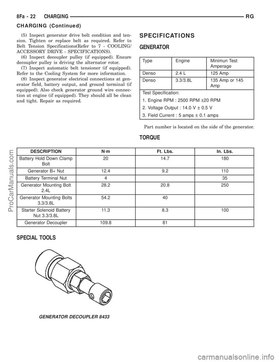
SPECIAL TOOLS
GENERATOR DECOUPLER 8433
8Fa - 22 CHARGINGRG
CHARGING (Continued)
ProCarManuals.com