Engine ground CHRYSLER TOWN AND COUNTRY 2002 Workshop Manual
[x] Cancel search | Manufacturer: CHRYSLER, Model Year: 2002, Model line: TOWN AND COUNTRY, Model: CHRYSLER TOWN AND COUNTRY 2002Pages: 2399, PDF Size: 57.96 MB
Page 481 of 2399
INSTALLATION
INSTALLATION - 2.4L
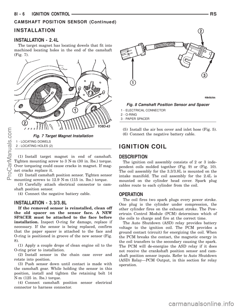
The target magnet has locating dowels that fit into
machined locating holes in the end of the camshaft
(Fig. 7).
(1) Install target magnet in end of camshaft.
Tighten mounting screw to 3 N´m (30 in. lbs.) torque.
Over torqueing could cause cracks in magnet. If mag-
net cracks replace it.
(2) Install camshaft position sensor. Tighten sensor
mounting screws to 12.9 N´m (115 in. lbs.) torque.
(3) Carefully attach electrical connector to cam-
shaft position sensor.
(4) Connect the negative battery cable.
INSTALLATION - 3.3/3.8L
If the removed sensor is reinstalled, clean off
the old spacer on the sensor face. A NEW
SPACER must be attached to the face before
installation.Inspect O-ring for damage, replace if
necessary. If the sensor is being replaced, confirm
that the paper spacer is attached to the face and
O-ring is positioned in groove of the new sensor (Fig.
8).
(1) Apply a couple drops of clean engine oil to the
O-ring prior to installation.
(2) Install sensor in the chain case cover and
rotate into position.
(3) Push sensor down until contact is made with
the camshaft gear. While holding the sensor in this
position, install and tighten the retaining bolt 14
N´m (125 in. lbs.) torque.
(4) Connect camshaft position sensor electrical
connector to harness connector.(5) Install the air box cover and inlet hose (Fig. 5).
(6) Connect the negative battery cable.
IGNITION COIL
DESCRIPTION
The ignition coil assembly consists of 2 or 3 inde-
pendent coils molded together (Fig. 9) or (Fig. 10).
The coil assembly for the 3.3/3.8L is mounted on the
intake manifold. The coil assembly for the 2.4L is
mounted on the cylinder head cover. Spark plug
cables route to each cylinder from the coil.
OPERATION
The coil fires two spark plugs every power stroke.
One plug is the cylinder under compression, the
other cylinder fires on the exhaust stroke. The Pow-
ertrain Control Module (PCM) determines which of
the coils to charge and fire at the correct time.
The Auto Shutdown (ASD) relay provides battery
voltage to the ignition coil. The PCM provides a
ground contact (circuit) for energizing the coil. When
the PCM breaks the contact, the magnetic energy in
the coil transfers to the secondary causing the spark.
The PCM will de-energize the ASD relay if it does
not receive the crankshaft position sensor and cam-
shaft position sensor inputs. Refer to Auto Shutdown
(ASD) RelayÐPCM Output, in this section for relay
operation.
Fig. 7 Target Magnet Installation
1 - LOCATING DOWELS
2 - LOCATING HOLES (2)
Fig. 8 Camshaft Position Sensor and Spacer
1 - ELECTRICAL CONNECTOR
2 - O-RING
3 - PAPER SPACER
8I - 6 IGNITION CONTROLRS
CAMSHAFT POSITION SENSOR (Continued)
ProCarManuals.com
Page 484 of 2399

(3) On All Wheel Drive vehicles install the PTU
(Power Transfer Unit) for the rear wheels, refer to
the Transmission section for more information.
(4) Lower vehicle.
(5) Connect the negative cable.
SPARK PLUG
DESCRIPTION
DESCRIPTION - STANDARD 4 CYLINDER
All engines use resistor spark plugs. They have
resistance values ranging from 6,000 to 20,000 ohms
when checked with at least a 1000 volt spark plug
tester.
Do not use an ohm meter to check the resis-
tance of the spark plugs. This will give an inac-
curate reading.
Refer to the Specifications section for gap and type
of spark plug.
DESCRIPTION - PLATINUM PLUGS
The V6 engines use platinum resistor spark plugs.
They have resistance values of 6,000 to 20,000 ohms
when checked with at least a 1000 volt tester. Forspark plug identification and specifications, Refer to
the Specifications section.
Do not use an ohm meter to check the resis-
tance of the spark plugs. This will give an inac-
curate reading.
When the spark plugs use a single or double plat-
inum tips and they have a recommended service life
of 100,000 miles for normal driving conditions per
schedule A in this manual. The spark plugs have a
recommended service life of 75,000 miles for severe
driving conditions per schedule B in this manual. A
thin platinum pad is welded to both or center elec-
trode end(s) as show in (Fig. 13). Extreme care must
be used to prevent spark plug cross threading, mis-
gaping (Fig. 14) and ceramic insulator damage dur-
ing plug removal and installation.
CAUTION: Cleaning of the platinum plug may dam-
age the platinum tip.
REMOVAL
When replacing the spark plugs and spark plug
cables, route the cables correctly and secure them in
the appropriate retainers. Failure to route the cables
properly can cause the radio to reproduce ignition
noise, cross ignition of the spark plugs orshort cir-
cuit the cables to ground.
Always remove cables by grasping at the boot,
rotating the boot 1/2 turn, and pulling straight back
in a steady motion.
(1) Prior to removing the spark plug, spray com-
pressed air around the spark plug hole and the area
around the spark plug.
(2) Remove the spark plug using a quality socket
with a foam insert.
(3) Inspect the spark plug condition.
Fig. 12 Knock Sensor
1 - GENERATOR
2 - INTAKE MANIFOLD
3 - KNOCK SENSOR
4-STARTER
Fig. 13 Platinum Pads
1 - APPLY ANTI-SEIZE COMPOUND HERE ONLY
2 - PLATINUM SPARK SURFACE
RSIGNITION CONTROL8I-9
KNOCK SENSOR (Continued)
ProCarManuals.com
Page 503 of 2399
OPERATION - TURN SIGNAL SYSTEM.......21
DIAGNOSIS AND TESTING - MULTI-
FUNCTION SWITCH...................22
REMOVAL.............................22
INSTALLATION.........................22
PARK/TURN SIGNAL LAMP
REMOVAL.............................22
INSTALLATION.........................22
PARK/TURN SIGNAL LAMP - EXPORT
REMOVAL.............................22
INSTALLATION.........................23
REAR FOG LAMP - EXPORT
DESCRIPTION.........................23REPEATER LAMP - EXPORT
REMOVAL.............................23
INSTALLATION.........................23
TAIL LAMP
REMOVAL.............................23
INSTALLATION.........................23
TAIL LAMP - EXPORT
REMOVAL.............................23
INSTALLATION.........................24
TAIL LAMP UNIT
REMOVAL.............................24
INSTALLATION.........................24
LAMPS/LIGHTING - EXTERIOR
DESCRIPTION
LAMP SYSTEMS
Lighting circuits are protected by fuses. Lighting
circuits require an overload protected power source,
on/off device, lamps and body ground to operate prop-
erly. Plastic lamps require a wire in the harness to
supply body ground to the lamp socket. Replace sock-
ets and bulbs that are corroded.
Some of the interior and exterior lighting functions
are governed by the Body Control Module (BCM).
The headlamp, dome, and the door ajar switches pro-
vide signals to the BCM. The BCM in turn sends a
Programmable Communication Interface (PCI) bus
message to the Front Control Module (FCM) to
enable the necessary drivers to set the required illu-
mination configuration.
Wire connectors can make intermittent contact or
become corroded. Before coupling wire connectors,
inspect the terminals inside the connector. Male ter-
minals should not be bent or disengaged from the
insulator. Female terminals should not be sprung
open or disengaged from the insulator. Bent and
sprung terminals can be repaired using needle nose
pliers and pick tool. Corroded terminals appear
chalky or green. Corroded terminals should be
replaced to avoid recurrence of the problem symp-
toms.
Begin electrical system failure diagnosis by testing
related fuses in the fuse block and intelligent power
module. Verify that bulbs are in good condition and
test continuity of the circuit ground. Refer to the
appropriate wiring information.
AUTOMATIC HEADLAMP SYSTEM
The Automatic Headlamp system turns the instru-
mentation and exterior illumination lamps ON when
the ambient light levels are Night and the engine
RPM is 450 or above, and OFF when light levels are
Day.
DAYTIME RUNNING LAMPS
Operating the high-beam headlamps at reduced
power provides daytime running lamps, which are
required on all new Canadian vehicles.
HEADLAMPS ON WITH WINDSHIELD WIPERS
For vehicles equipped with the Automatic Head-
lamp System, the instrumentation and exterior illu-
mination lamps will be turned ON when the
headlamp switch is in the AUTO position, RPM >
450 and the windshield wipers have been in the
intermittent, low or high mode of operation for more
than ten seconds. When the windshield wipers are
turned OFF the Body Control Module will determine
if the instrumentation and exterior illumination
lamps should remain ON base upon the current
ambient light level.
HEADLAMP SYSTEM
The configuration of the headlamp system of head-
lamps, park lamps and fog lamps is determined by
the BCM. The BCM determines the lighting configu-
ration as a result of the inputs from the ignition
switch, headlamp switch and multi-function switch. A
PCI bus is transmitted from the BCM to the FCM to
enable the necessary drivers to set the illumination
configuration. Four wires are connected between the
headlamp switch and the BCM. The first wire con-
tains information regarding the position of the head-
lamp switch (Off, Automatic Headlamps, Automatic
Headlamp switch fog, Park with Fog, Head, or Head
with Fog Lamps). The second wire contains informa-
tion regarding the position of the dimmer switch
(Dome Lamp, Daytime Brightness, Dimming Level or
Off). The third wire is a dedicated signal return
(ground) wire. The fourth wire provides power to the
front fog lamp indicator.
HEADLAMP TIME DELAY SYSTEM
The headlamp time delay system is controlled by
the Body Control Module (BCM) via a PCI bus mes-
8L - 2 LAMPS/LIGHTING - EXTERIORRS
ProCarManuals.com
Page 508 of 2399
(3) Install the retaining screws.
(4) Reconnect the battery negative cable.
FOG LAMP
DIAGNOSIS AND TESTING - FOG LAMP
When a vehicle experiences problems with the fog
lamp system, verify the condition of the battery con-
nections, fuses, charging system, fog lamp bulbs, wire
connectors, relay, high beam switch, and headlamp
switch. Refer to the appropriate wiring information.
Each vehicle is equipped with various lamp assem-
blies. A good ground is necessary for proper lighting
operation. Grounding is provided by the lamp socket
when it comes in contact with the metal body, or
through a separate ground wire.
When changing lamp bulbs check the socket for
corrosion. If corrosion is present, clean it with a wire
brush.
When it is necessary to remove components to ser-
vice another, it should not be necessary to apply
excessive force or bend a component to remove it.
Before damaging a trim component, verify hidden
fasteners or captured edges are not holding the com-
ponent in place.
FOG LAMP DIAGNOSIS
CONDITION POSSIBLE CAUSES CORRECTION
FOG LAMPS ARE DIM
WITH ENGINE IDLING
OR IGNITION TURNED
OFF.1. Loose or corroded battery
cables.1. Clean and secure battery cable clamps and
posts.
2. Loose or worn generator drive
belt.2. Adjust or replace generator drive belt.
3. Charging system output too low. 3. Test and repair charging system. Refer to
Electrical, Charging,
4. Battery has insufficient charge. 4. Test battery state-of-charge. Refer to
Electrical, Battery System.
5. Battery is sulfated or shorted. 5. Load test battery. Refer to Electrical, Battery
System.
6. Poor lighting circuit Z349/Z248
ground.6. Test for voltage drop across Z349/248
ground locations. Refer to Electrical, Wiring
Information.
FOG LAMP BULBS
BURN OUT
FREQUENTLY1. Charging system output too
high.1. Test and repair charging system. Refer to
Electrical, Charging.
2. Loose or corroded terminals or
splices in circuit.2. Inspect and repair all connectors and splices.
Refer to Electrical, Wiring Information.
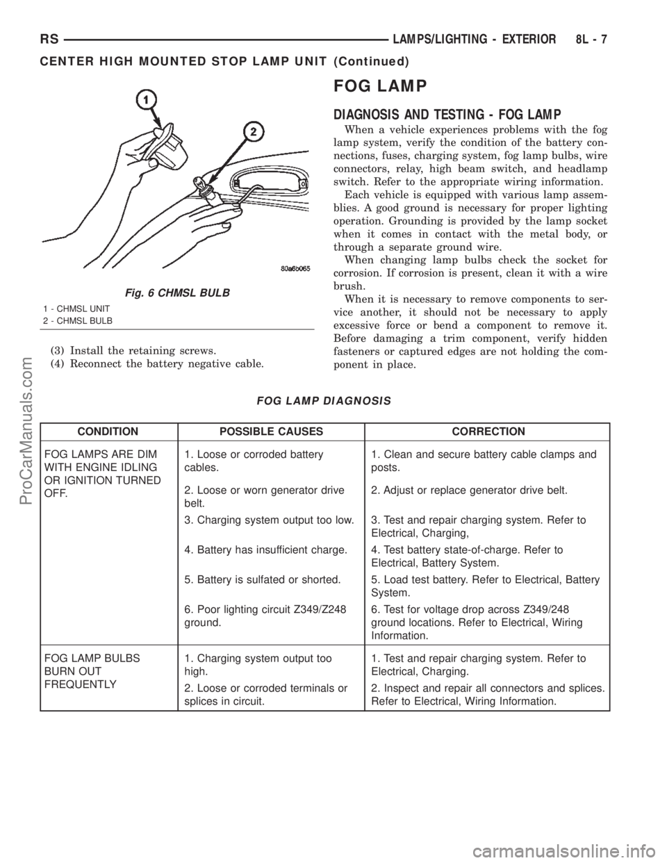
Fig. 6 CHMSL BULB
1 - CHMSL UNIT
2 - CHMSL BULB
RSLAMPS/LIGHTING - EXTERIOR8L-7
CENTER HIGH MOUNTED STOP LAMP UNIT (Continued)
ProCarManuals.com
Page 509 of 2399
CONDITION POSSIBLE CAUSES CORRECTION
FOG LAMPS ARE DIM
WITH ENGINE
RUNNING ABOVE IDLE1. Charging system output too low. 1. Test and repair charging system. Refer to
Electrical, Charging.
2. Poor lighting circuit Z349/Z248
ground.2. Test for voltage drop across Z349/Z248
ground locations. Refer to Electrical, Wiring
Information.
3. High resistance in fog lamp
circuit.3. Test amperage draw of fog lamp circuit.
FOG LAMPS FLASH
RANDOMLY1. Poor lighting circuit Z349/Z248
ground.1. Test for voltage drop across Z349/Z248
ground locations. Refer to Electrical, Wiring
Information.
2. Variable resistance in fog lamp
circuit.2. Test amperage draw of fog lamp circuit.
3. Faulty fog lamp switch (part of
headlamp switch).3. Replace headlamp switch.
4. Loose or corroded terminals or
splices in circuit.4. Inspect and repair all connectors and splices.
Refer to Electrical, Wiring Information.
5. Is relay engaging properly? 5. Verify function of fog lamp relay in IPM.
6. PCI Bus Communication. 6. Verify PCI bus message (fog lamp info)
transmitted from BCM and received by FCM.
FOG LAMPS DO NOT
ILLUMINATE1. Blown fuse for fog lamp. 1. Replace fuse. Refer to Electrical, Wiring
Information.
2. No Z349/Z248 ground at fog
lamps.2. Repair circuit ground. Refer to Electrical,
Wiring Information.
3. Faulty fog lamp switch (part of
headlamp switch).3. Replace headlamp switch.
4. Broken connector terminal or
wire splice in fog lamp circuit.4. Repair connector terminal or wire splice.
5. Faulty or burned out bulb. 5. Replace bulb.
6. Is relay engaging? 6. Verify function of fog lamp relay in IPM.
7. PCI Bus Communication. 7. Verify PCI bus message (fog lamp info)
transmitted from BCM and received by FCM.
8L - 8 LAMPS/LIGHTING - EXTERIORRS
FOG LAMP (Continued)
ProCarManuals.com
Page 513 of 2399

(4) Install the headlamp unit.
(5) Connect the battery negative cable.
HEADLAMP
DIAGNOSIS AND TESTING - HEADLAMP
When a vehicle experiences problems with the
headlamp system, verify the condition of the battery
connections, fuses, charging system, headlamp bulbs,
wire connectors, relay, high beam switch, dimmer
switch, and headlamp switch. Refer to the appropri-
ate wiring information.
Each vehicle is equipped with various lamp assem-
blies. A good ground is necessary for proper lighting
operation. Grounding is provided by the lamp socket
when it comes in contact with the metal body, or
through a separate ground wire.
When changing lamp bulbs check the socket for
corrosion. If corrosion is present, clean it with a wire
brush.
When it is necessary to remove components to ser-
vice another, it should not be necessary to apply
excessive force or bend a component to remove it.
Before damaging a trim component, verify hidden
fasteners or captured edges are not holding the com-
ponent in place.
HEADLAMP DIAGNOSIS
CONDITION POSSIBLE CAUSES CORRECTION
HEADLAMPS ARE DIM
WITH ENGINE IDLING
OR IGNITION TURNED
OFF.1. Loose or corroded battery
cables.1. Clean and secure battery cable clamps and
posts.
2. Loose or worn generator drive
belt.2. Adjust or replace generator drive belt.
3. Charging system output too low. 3. Test and repair charging system, refer to
Electrical, Charging
4. Battery has insufficient charge. 4. Test battery state-of-charge, refer to
Electrical, Battery System.
5. Battery is sulfated or shorted. 5. Load test battery, refer to Electrical, Battery
System.
6. Poor lighting circuit Z343/Z344-
ground.6. Test for voltage drop across Z343/Z344-
ground locations, refer to Electrical, Wiring
Diagram Information.
HEADLAMP BULBS
BURN OUT
FREQUENTLY.1. Integrated Power Module (IPM)
not controlling voltage.1. Test and repair Integrated Power Module.
2. Loose or corroded terminals or
splices in circuit.2. Inspect and repair all connectors and splices.
Refer to Electrical, Wiring Information.
Fig. 11 FRONT POSITION LAMP
1 - TURN SIGNAL LAMP
2 - HIGH BEAM LAMP
3 - FRONT POSITION LAMP
4 - LOW BEAM LAMP
8L - 12 LAMPS/LIGHTING - EXTERIORRS
FRONT POSITION LAMP - EXPORT (Continued)
ProCarManuals.com
Page 514 of 2399

CONDITION POSSIBLE CAUSES CORRECTION
HEADLAMPS ARE DIM
WITH ENGINE
RUNNING ABOVE IDLE.1. Charging system output too low. 1. Test and repair charging system, refer to
Electrical, Wiring Information.
2. Poor lighting circuit Z343/Z344-
ground.2. Test for voltage drop across Z343/Z344-
ground locations, refer to Electrical, Wiring
Information.
3. High resistance in headlamp
circuit.3. Test amperage draw of headlamp circuit.
HEADLAMPS FLASH
RANDOMLY1. Poor lighting circuit Z343/Z344-
ground.1. Test for voltage drop across Z343/Z344-
ground locations, refer to Electrical, Wiring
Information.
2. Variable resistance in headlamp
circuit.2. Test amperage draw of headlamp circuit.
3. Loose or corroded terminals or
splices in circuit.3. Inspect and repair all connectors and splices,
refer to Electrical, Wiring Information.
4. Faulty headlamp switch. 4. Replace headlamp switch.
HEADLAMPS DO NOT
ILLUMINATE.1. No voltage to headlamps. 1. Repair open headlamp circuit, refer to
Electrical, Wiring Information.
2. No Z343/Z344-ground at
headlamps.2. Repair circuit ground, refer to Electrical,
Wiring Information.
3. Broken connector terminal or
wire splice in headlamp circuit.3. Repair connector terminal or wire splice.
4. Faulty or burned out bulb. 4. Replace headlamp bulb(s).
5. Body Control Module
malfunction.5. Refer to appropriate Body Control Module
diagnostics.
6. PCI Bus Communication 6. Verify messages being transmitted by BCM
and received by FCM.
7. IPM/FCM Malfunction. 7. Refer to appropriate IPM/FCM diagnostics.
HEADLAMPS ON WITH
IGNITION IN RUN, WITH
HEADLAMP SWITCH
OFF.1. Faulty headlamp switch. 1. Replace headlamp switch (review BCM
logged faults).
2. Diagnostic tool indicates (4.7 -
5.0V) on headlamp switch input to
BCM.2. Inspect and repair terminals, connectors and
open circuits.
3. PCI Bus Communication. 3. Verify messages being transmitted by BCM
and received by FCM.
RSLAMPS/LIGHTING - EXTERIOR8L-13
HEADLAMP (Continued)
ProCarManuals.com
Page 585 of 2399

REMOTE KEYLESS ENTRY
MODULE
DESCRIPTION
The RKE module is capable of retaining up to four
different Vehicle Access Codes.
OPERATION
Whenever the vehicle battery power is interrupted
the RKE Module will retain all vehicle access codes
in its memory. When replacing or adding a key fob
transmitter (maximum 4) a DRB IIItscan tool is
required to program the RKE Module to accept the
new Vehicle Access Code if a customer owned trans-
mitter is not available. Refer to Electrical, Remote
Keyless Entry Module, Standard Procedure - Pro-
gramming RKE Module or the Proper Body Diagnos-
tic Procedures manual.
DIAGNOSIS AND TESTING - REMOTE KEYLESS
ENTRY MODULE
Refer to the appropriate wiring information. The
wiring information includes wiring diagrams, proper
wire and connector repair procedures, further details
on wire harness routing and retention, as well as
pin-out and location views for the various wire har-
ness connectors, splices and grounds. Refer to the
proper Body Diagnostic Procedures Manual for test-
ing the Remote Keyless Entry system using a DRB
IIItscan tool. Also refer to other interrelated sys-
tems groups within this manual:
²Vehicle Theft Security System
²Power Seats
²Power Mirrors
STANDARD PROCEDURE - PROGRAMMING
RKE MODULE
(1) Using a functional key fob transmitter, unlock
the vehicle and disarm the Vehicle Theft Security
System.
(2) Insert ignition key into the ignition switch.
(3) Turn the ignition switch to RUN position with-
out starting engine.
(4) Using a functional key fob transmitter, press
and hold the UNLOCK button for a minimum five
seconds (maximum ten seconds).
(5) While still holding UNLOCK button, and
before ten seconds passes, press the PANIC button
and release both at the same time. A single chime
will sound to verify that the RKE module is set to
receive the new Vehicle Access Code(s).
(6) Within 30 seconds of the chime, press and
release the ªLOCKº and ªUNLOCKº buttons on the
transmitter at the same time. Then press and release
any one of the buttons. The BCM will sound anabbreviated chime to acknowledge that the program-
ming of the transmitter has been completed and was
successful.
(7) Repeat step 6 for all transmitters that will be
used with this vehicle (up to 4 total).
(8) Programming mode will last for 30 seconds. To
get out of programming mode sooner, turn the igni-
tion OFF. A single chime will sound to verify that the
RKE module will no longer accept additional Vehicle
Access Code(s).
(9) When Vehicle Access Code(s) programming is
complete, turn the ignition switch to the OFF posi-
tion and verify RKE system operation using each key
fob.
NOTE:
Only the two key fob transmitters that have been
programmed to the memory seat and mirror system
will operate it. If any key fob is replaced, the mem-
ory seat and mirror module will require program-
ming. (Refer to 8 - ELECTRICAL/POWER SEATS -
DIAGNOSIS AND TESTING).
REMOVAL
(1) Disconnect and isolate the battery negative
cable.
(2) Remove instrument panel top cover (Refer to
23 - BODY/INSTRUMENT PANEL/INSTRUMENT
PANEL TOP PAD - REMOVAL).
(3) Remove screws holding RKE module to instru-
ment panel.
(4) Disconnect wire connector from RKE module
(Fig. 4).
(5) Remove the RKE module from vehicle.
Fig. 4 RKE MODULE
1 - REMOTE KEYLESS ENTRY MODULE
2 - INSTRUMENT PANEL
3 - DEMISTER DUCT
8N - 44 POWER LOCKSRS
ProCarManuals.com
Page 639 of 2399
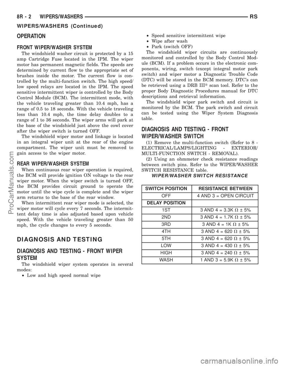
OPERATION
FRONT WIPER/WASHER SYSTEM
The windshield washer circuit is protected by a 15
amp Cartridge Fuse located in the IPM. The wiper
motor has permanent magnetic fields. The speeds are
determined by current flow to the appropriate set of
brushes inside the motor. The current flow is con-
trolled by the multi-function switch. The high speed/
low speed relays are located in the IPM. The speed
sensitive intermittent wiper is controlled by the Body
Control Module (BCM). The intermittent mode, with
the vehicle traveling greater than 10.4 mph, has a
range of 0.5 to 18 seconds. With the vehicle traveling
less than 10.4 mph, the time delay doubles to a
range of 1 to 36 seconds. The wiper arms will park at
the base of the windshield just above the cowl cover
after the wiper switch is turned OFF.
The windshield wiper motor and linkage is located
in an integral wiper unit at the rear of the engine
compartment. The wiper unit must be removed to
gain access to the wiper motor.
REAR WIPER/WASHER SYSTEM
When continuous rear wiper operation is required,
the BCM will provide ignition ON voltage to the rear
wiper motor. When the wiper switch is turned OFF,
the BCM provides circuit ground to operate the
motor until the wipe cycle is complete and the wiper
arm returns to the base of the rear window.
When intermittent rear wiper mode is selected, the
wiper motor will cycle every 7 seconds. The intermit-
tent delay time is also adjusted based upon vehicle
speed. With the vehicle traveling greater than 50
mph, the cycle changes to every 5 seconds.
DIAGNOSIS AND TESTING
DIAGNOSIS AND TESTING - FRONT WIPER
SYSTEM
The windshield wiper system operates in several
modes:
²Low and high speed normal wipe²Speed sensitive intermittent wipe
²Wipe after wash
²Park (switch OFF)
The windshield wiper circuits are continuously
monitored and controlled by the Body Control Mod-
ule (BCM). If a problem occurs in the electronic com-
ponents, wiring, switch (except integral motor park
switch) and wiper motor a Diagnostic Trouble Code
(DTC) will be stored in the BCM memory. DTC's can
be retrieved using a DRB IIItscan tool. Refer to the
proper Body Diagnostic Procedures manual for DTC
descriptions and retrieval information.
The windshield wiper park switch and circuit is
monitored by the BCM. The park switch and circuit
can be tested using the Wiper System Diagnosis
table.
DIAGNOSIS AND TESTING - FRONT
WIPER/WASHER SWITCH
(1) Remove the multi-function switch (Refer to 8 -
ELECTRICAL/LAMPS/LIGHTING - EXTERIOR/
MULTI-FUNCTION SWITCH - REMOVAL).
(2) Using an ohmmeter check resistance readings
between switch pins. Refer to the WIPER/WASHER
SWITCH RESISTANCE table.
WIPER/WASHER SWITCH RESISTANCE
SWITCH POSITION RESISTANCE BETWEEN
OFF 4 AND 3 = OPEN CIRCUIT
DELAY POSITION
1ST 3 AND 4 = 3.3KV 5%
2ND 3 AND 4 = 1.7KV 5%
3RD 3AND4=1KV 5%
4TH 3 AND 4 = 620V 5%
5TH 3 AND 4 = 620V 5%
LOW 3 AND 4 = 430V 5%
HIGH 3 AND4=240V 5%
WASH 1 AND 3 = 5.9KV 5%
8R - 2 WIPERS/WASHERSRS
WIPERS/WASHERS (Continued)
ProCarManuals.com
Page 649 of 2399
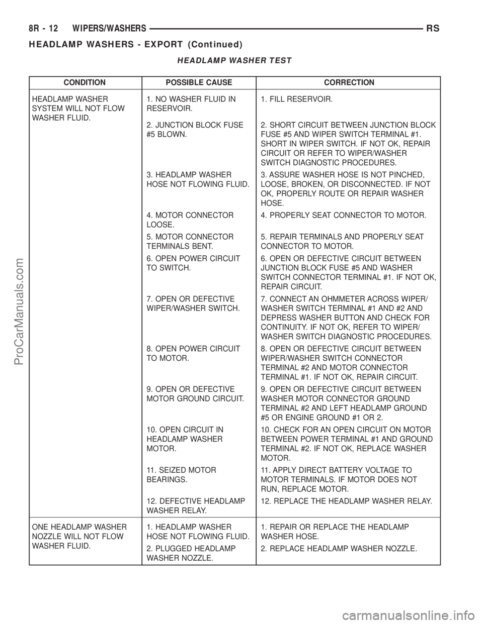
HEADLAMP WASHER TEST
CONDITION POSSIBLE CAUSE CORRECTION
HEADLAMP WASHER
SYSTEM WILL NOT FLOW
WASHER FLUID.1. NO WASHER FLUID IN
RESERVOIR.1. FILL RESERVOIR.
2. JUNCTION BLOCK FUSE
#5 BLOWN.2. SHORT CIRCUIT BETWEEN JUNCTION BLOCK
FUSE #5 AND WIPER SWITCH TERMINAL #1.
SHORT IN WIPER SWITCH. IF NOT OK, REPAIR
CIRCUIT OR REFER TO WIPER/WASHER
SWITCH DIAGNOSTIC PROCEDURES.
3. HEADLAMP WASHER
HOSE NOT FLOWING FLUID.3. ASSURE WASHER HOSE IS NOT PINCHED,
LOOSE, BROKEN, OR DISCONNECTED. IF NOT
OK, PROPERLY ROUTE OR REPAIR WASHER
HOSE.
4. MOTOR CONNECTOR
LOOSE.4. PROPERLY SEAT CONNECTOR TO MOTOR.
5. MOTOR CONNECTOR
TERMINALS BENT.5. REPAIR TERMINALS AND PROPERLY SEAT
CONNECTOR TO MOTOR.
6. OPEN POWER CIRCUIT
TO SWITCH.6. OPEN OR DEFECTIVE CIRCUIT BETWEEN
JUNCTION BLOCK FUSE #5 AND WASHER
SWITCH CONNECTOR TERMINAL #1. IF NOT OK,
REPAIR CIRCUIT.
7. OPEN OR DEFECTIVE
WIPER/WASHER SWITCH.7. CONNECT AN OHMMETER ACROSS WIPER/
WASHER SWITCH TERMINAL #1 AND #2 AND
DEPRESS WASHER BUTTON AND CHECK FOR
CONTINUITY. IF NOT OK, REFER TO WIPER/
WASHER SWITCH DIAGNOSTIC PROCEDURES.
8. OPEN POWER CIRCUIT
TO MOTOR.8. OPEN OR DEFECTIVE CIRCUIT BETWEEN
WIPER/WASHER SWITCH CONNECTOR
TERMINAL #2 AND MOTOR CONNECTOR
TERMINAL #1. IF NOT OK, REPAIR CIRCUIT.
9. OPEN OR DEFECTIVE
MOTOR GROUND CIRCUIT.9. OPEN OR DEFECTIVE CIRCUIT BETWEEN
WASHER MOTOR CONNECTOR GROUND
TERMINAL #2 AND LEFT HEADLAMP GROUND
#5 OR ENGINE GROUND #1 OR 2.
10. OPEN CIRCUIT IN
HEADLAMP WASHER
MOTOR.10. CHECK FOR AN OPEN CIRCUIT ON MOTOR
BETWEEN POWER TERMINAL #1 AND GROUND
TERMINAL #2. IF NOT OK, REPLACE WASHER
MOTOR.
11. SEIZED MOTOR
BEARINGS.11. APPLY DIRECT BATTERY VOLTAGE TO
MOTOR TERMINALS. IF MOTOR DOES NOT
RUN, REPLACE MOTOR.
12. DEFECTIVE HEADLAMP
WASHER RELAY.12. REPLACE THE HEADLAMP WASHER RELAY.
ONE HEADLAMP WASHER
NOZZLE WILL NOT FLOW
WASHER FLUID.1. HEADLAMP WASHER
HOSE NOT FLOWING FLUID.1. REPAIR OR REPLACE THE HEADLAMP
WASHER HOSE.
2. PLUGGED HEADLAMP
WASHER NOZZLE.2. REPLACE HEADLAMP WASHER NOZZLE.
8R - 12 WIPERS/WASHERSRS
HEADLAMP WASHERS - EXPORT (Continued)
ProCarManuals.com