ignition CHRYSLER TOWN AND COUNTRY 2008 5.G Workshop Manual
[x] Cancel search | Manufacturer: CHRYSLER, Model Year: 2008, Model line: TOWN AND COUNTRY, Model: CHRYSLER TOWN AND COUNTRY 2008 5.GPages: 531, PDF Size: 4.51 MB
Page 194 of 531
Ignition OFF Operation
The power sunroof switch will remain active for 10
minutes after the ignition switch is turned OFF. Opening
either front door will cancel this feature.
Auto-Express with Anti±Pinch Protection
During express closing, anytime an obstacle that restricts
glass movement is detected, the motor will stop and
reverse travel to avoid pinching the object.
Auto Express will stop and reverse travel up to three
times in succession. After the third time, Auto Express
will enter a manual operation mode. This allows the
operator to manually control the power switch in order to
close or open the sunroof in case of a malfunction.
Wind Buffeting
Wind buffeting can be described as the perception of
pressure on the ears or a helicopter type sound in the
ears. Your vehicle may exhibit wind buffeting with the
windows down, or the sunroof (if equipped) in certain
open or partially open positions. This is a normal occur-
rence and can be minimized. If the buffeting occurs with
the rear windows open, open the front and rear windows
together to minimize the buffeting. If the buffeting occurs
with the sunroof open, adjust the sunroof opening to
minimize the buffeting or open any window.
Sunroof Maintenance
Use only a non-abrasive cleaner and a soft cloth to clean
the glass panel.
192 UNDERSTANDING THE FEATURES OF YOUR VEHICLE
Page 195 of 531
ELECTRICAL POWER OUTLETS Ð IF EQUIPPED
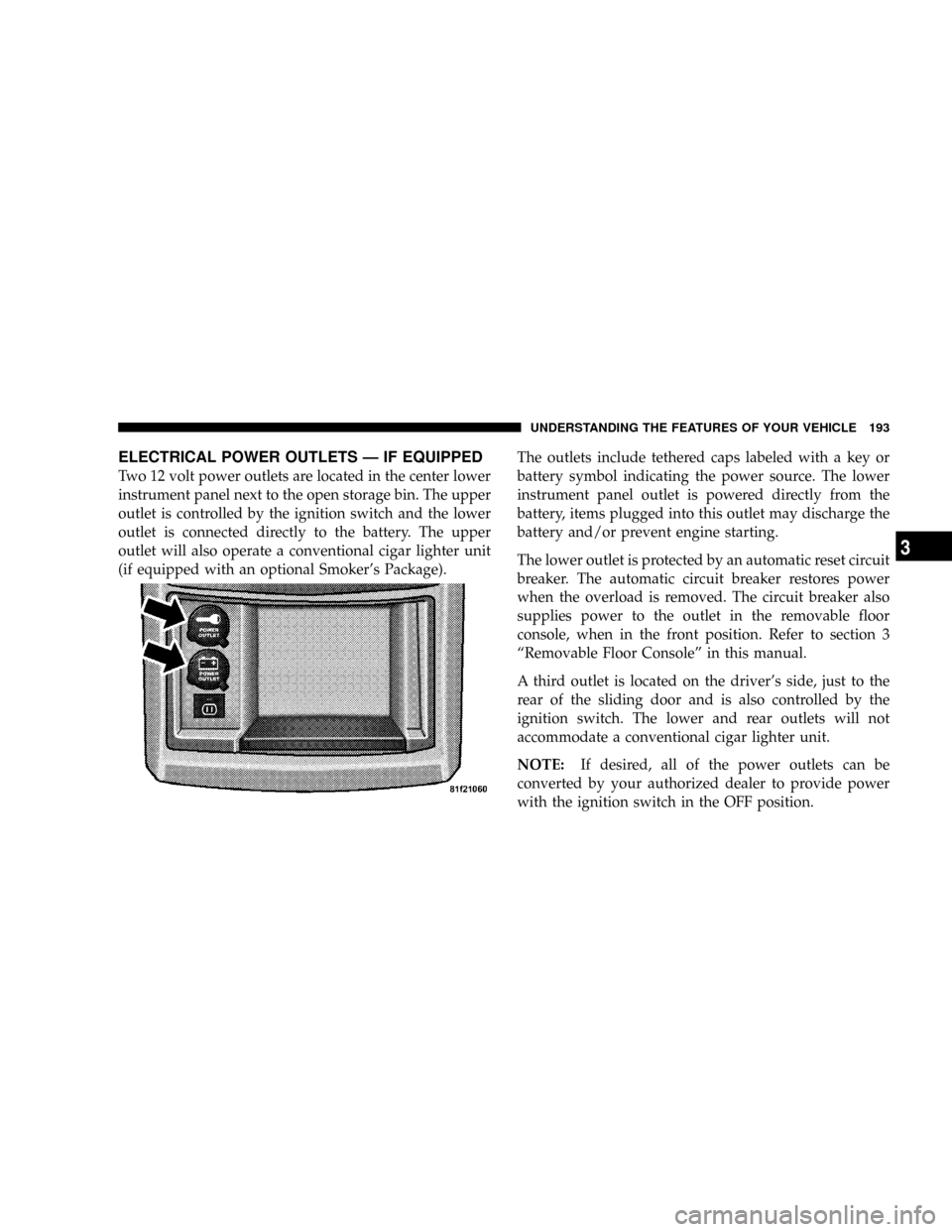
Two 12 volt power outlets are located in the center lower
instrument panel next to the open storage bin. The upper
outlet is controlled by the ignition switch and the lower
outlet is connected directly to the battery. The upper
outlet will also operate a conventional cigar lighter unit
(if equipped with an optional Smoker's Package).The outlets include tethered caps labeled with a key or
battery symbol indicating the power source. The lower
instrument panel outlet is powered directly from the
battery, items plugged into this outlet may discharge the
battery and/or prevent engine starting.
The lower outlet is protected by an automatic reset circuit
breaker. The automatic circuit breaker restores power
when the overload is removed. The circuit breaker also
supplies power to the outlet in the removable floor
console, when in the front position. Refer to section 3
ªRemovable Floor Consoleº in this manual.
A third outlet is located on the driver's side, just to the
rear of the sliding door and is also controlled by the
ignition switch. The lower and rear outlets will not
accommodate a conventional cigar lighter unit.
NOTE:If desired, all of the power outlets can be
converted by your authorized dealer to provide power
with the ignition switch in the OFF position.
UNDERSTANDING THE FEATURES OF YOUR VEHICLE 193
3
Page 225 of 531
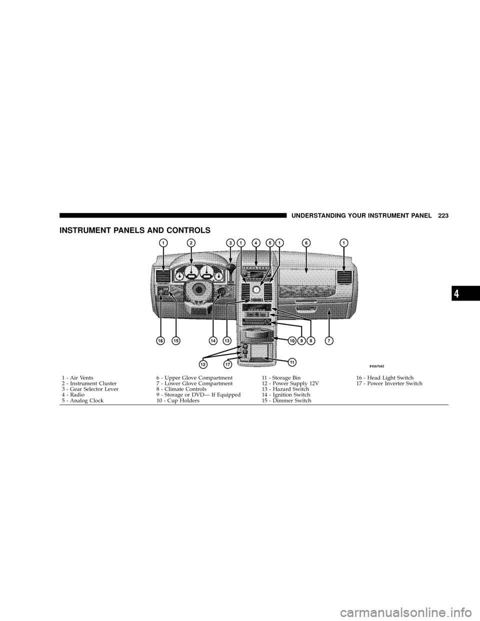
INSTRUMENT PANELS AND CONTROLS
1 - Air Vents 6 - Upper Glove Compartment 11 - Storage Bin 16 - Head Light Switch
2 - Instrument Cluster 7 - Lower Glove Compartment 12 - Power Supply 12V 17 - Power Inverter Switch
3 - Gear Selector Lever 8 - Climate Controls 13 - Hazard Switch
4 - Radio 9 - Storage or DVDÐ If Equipped 14 - Ignition Switch
5 - Analog Clock 10 - Cup Holders 15 - Dimmer Switch
UNDERSTANDING YOUR INSTRUMENT PANEL 223
4
Page 228 of 531
INSTRUMENT CLUSTER DESCRIPTIONS
1. Fuel Gauge
The pointer shows the level of fuel in the fuel tank when
the ignition switch is in the ON position.
2. Low Fuel Light
When the fuel level reaches approximately 2.0 gals
(7.8 L) this light will turn on and remain on until
fuel is added.
3. Electronic Throttle Control (ETC.) Light
This light informs you of a problem with the
Electronic Throttle Control system. If a prob-
lem is detected, the light will come on while the
engine is running. Cycle the ignition key when
the vehicle has completely stopped and the gear selector
is placed in the PARK position. The light should turn off.
If the light remains lit with the engine running your
vehicle will usually be drivable, however, see your
authorized dealer for service as soon as possible. If thelight is flashing when the engine is running, immediate
service is required and you may experience reduced
performance, an elevated/rough idle or engine stall and
your vehicle may require towing. The light will come ON
when the ignition is first turned on and remain on briefly
as a bulb check. If the light does not come on during
starting, have the system checked by an authorized
dealer.
4. Voltage Light
This light monitors the electrical system voltage.
The light should turn on momentarily as the
engine is started. If the light stays on or turns on while
driving, it indicates a problem with the charging system.
Immediate service should be obtained.
226 UNDERSTANDING YOUR INSTRUMENT PANEL
Page 231 of 531
For additional information on Tire Pressures, refer to
Section 5 Ð Starting and Operating, ªTire Inflation
Pressuresº of this manual.
6. Oil Pressure Warning Light
This light shows low engine oil pressure. The light
should turn on momentarily when the engine is
started. If the light turns on while driving, stop the
vehicle and shut off the engine as soon as possible. A
chime will sound for four minutes when this light turns
on.
Do not operate the vehicle until the cause is corrected.
This light does not show how much oil is in the engine.
The engine oil level must be checked under the hood.
7. Engine Temperature Warning Light
This light warns of an overheated engine condi-
tion. If the engine is critically hot, a continuouschime will sound for four minutes. After the chime turns
off, the engine will still be critically hot until the light
turns off.
8. Speedometer
Indicates vehicle speed.
9. Turn Signal Indicators
The arrow will flash with the exterior turn signal
when the turn signal lever is operated.
If the vehicle electronics sense that the vehicle has
traveled about one mile with the turn signals on, a
continuous chime will sound to alert you to turn the
signals off. If either indicator flashes at a rapid rate, check
for a defective outside light bulb.
10. Electronic Stability Program (ESP) Indicator Light
The malfunction lamp for the ESP is combined
with BAS. The yellow ªESP/BAS Warning
Lampº comes on when the ignition switch is
UNDERSTANDING YOUR INSTRUMENT PANEL 229
4
Page 232 of 531
turned to the ªONº position. They should go out with the
engine running. If the ªESP/BAS Warning Lampº comes
on continuously with the engine running, a malfunction
has been detected in either the ESP or the BAS system. If
this light remains on after several ignition cycles, and the
vehicle has been driven several miles at speeds greater
than 30 mph (48 km/h), see your authorized dealer as
soon as possible.
11. Brake System Warning Light
This light monitors various brake functions,
including brake fluid level and parking brake
application. If the brake light turns on, it may
indicate that the parking brake is applied, that
the brake fluid level is low, or that there is a problem with
the anti-lock brake system (if equipped).
The dual brake system provides a reserve braking capac-
ity in the event of a failure to a portion of the hydraulic
system. Failure of either half of the dual brake system isindicated by the Brake Warning Light which will turn on
when the brake fluid level in the master cylinder has
dropped below a specified level.
The light will remain on until the cause is corrected.
NOTE:The light may flash momentarily during sharp
cornering maneuvers which change fluid level condi-
tions. The vehicle should have service performed, and
the brake fluid level checked.
If brake failure is indicated, immediate repair is neces-
sary.
WARNING!
Driving a vehicle with the brake light on is danger-
ous. Part of the brake system may have failed. It will
take longer to stop the vehicle. You could have an
accident. Have the vehicle checked immediately.
230 UNDERSTANDING YOUR INSTRUMENT PANEL
Page 233 of 531
Vehicles equipped with the Anti-Lock Brake System
(ABS), are also equipped with Electronic Brake Force
Distribution (EBD). In the event of an EBD failure, the
Brake Warning Light will turn on along with the ABS
Light. Immediate repair to the ABS system is required.
The operation of the Brake Warning Light can be checked
by turning the ignition switch from the OFF position to
the ON position. The light should illuminate for approxi-
mately two seconds. The light should then turn off unless
the parking brake is applied or a brake fault is detected.
If the light does not illuminate, have the light inspected
by an authorized dealer.
The light also will turn on when the parking brake is
applied with the ignition switch in the ON position.
NOTE:This light shows only that the parking brake is
applied. It does not show the degree of brake application.12. Vehicle Security Light Ð If Equipped
This light will flash at a fast rate for approxi-
mately 16 seconds when the vehicle security
alarm is arming and then will flash slowly until
the system is disarmed.
13. Anti-Lock Brake System Light
This light monitors the Anti-Lock Brake Sys-
tem. The light will turn on when the ignition
switch is turned to the ON position and may
stay on for as long as four seconds.
If the ABS light remains on or turns on while driving, it
indicates that the Anti-Lock portion of the brake system
is not functioning and that service is required. However,
the conventional brake system will continue to operate
normally if the BRAKE warning light is not on.
If the ABS light is on, the brake system should be serviced
as soon as possible to restore the benefits of Anti-Lock
UNDERSTANDING YOUR INSTRUMENT PANEL 231
4
Page 234 of 531
brakes. If the ABS light does not turn on when the
Ignition switch is turned to the ON position, have the
light inspected by an authorized dealer.
14. Electronic Stability Program (ESP) Indicator
Light/Traction Control System (TCS) Indicator Light
If this indicator light flashes during accelera-
tion, apply as little throttle as possible. While
driving, ease up on the accelerator. Adapt your
speed and driving to the prevailing road con-
ditions, and do not switch off the ESP, or TCS.
15. Tachometer
The red segments indicate the maximum permissible
engine revolutions per minute (RPM x 1000) for each gear
range. Before reaching the red area, ease up on the
accelerator.16. High Beam Light
This light shows that the headlights are on high
beam. Pull the turn signal lever towards the
steering wheel to switch the headlights from high or low
beam.
17. Front Fog Light Indicator Ð If Equipped
This light shows when the front fog lights are ON.
18. Seat Belt Reminder Light
When the ignition switch is first turned ON, this
light will turn on for five to eight seconds as a bulb
check. During the bulb check, if the driver's seat
belt is unbuckled, a chime will sound. After the bulb
check or when driving, if the driver's seat belt remains
unbuckled, the Seat Belt Reminder Light will illuminate
and the chime will sound. Refer to the Occupant Re-
straints section for more information.
232 UNDERSTANDING YOUR INSTRUMENT PANEL
Page 235 of 531
19. Malfunction Indicator Light
This light is part of an onboard diagnostic system
called OBD that monitors engine and automatic
transmission control systems. The light will illu-
minate when the key is in the ON position before engine
start. If the bulb does not come on when turning the key
from OFF to ON, have the condition checked promptly.
Certain conditions such as a loose or missing gas cap,
poor fuel quality, etc. may illuminate the light after
engine start. The vehicle should be serviced if the light
stays on through several of your typical driving cycles. In
most situations the vehicle will drive normally and will
not require towing.
If the Malfunction Indicator Light flashes when the
engine is running, serious conditions may exist that
could lead to immediate loss of power or severe catalytic
converter damage. The vehicle should be serviced as
soon as possible if this occurs.20. Airbag Light
This light turns on and remains on for seven
seconds as a bulb check when the ignition
switch is first turned ON. If the light is not on
during starting, stays on, or turns on while
driving, have the system inspected by an authorized
dealer as soon as possible.
21. Temperature Gauge
The temperature gauge shows engine coolant tem-
perature. Any reading within the normal range
indicates that the engine cooling system is operat-
ing satisfactorily.
The gauge pointer will likely indicate a higher tempera-
ture when driving in hot weather, up mountain grades,
or when towing a trailer. It should not be allowed to
exceed the upper limits of the normal operating range.
UNDERSTANDING YOUR INSTRUMENT PANEL 233
4
Page 238 of 531
NOTE:Some of the above warnings will be displayed in
the Compass Mini-Trip Computer / Electronic Vehicle
Information Center Display Area under the Speedometer.
Refer toº Compass Mini-Trip Computer (CMTC) Ð If
Equippedº, later in this section for more information.
CHAngE OIL
Your vehicle is equipped with an engine oil change
indicator system. TheCHAngE OILmessage will flash in
the instrument cluster odometer for approximately 12
seconds after a single chime has sounded to indicate the
next scheduled oil change interval. The engine oil change
indicator system is duty cycle-based, which means the
engine oil change interval may fluctuate dependent upon
your personal driving style.
Unless reset, this message will continue to display each
time you turn the ignition switch to the ON/RUN
position. To turn off the message temporarily, press andrelease the Trip / Odometer Display reset button on the
instrument cluster. To reset the oil change indicator
system (after performing the scheduled maintenance)
refer to the following procedure.
1. Turn the ignition switch to the ON position (Do not
start the engine).
2. Fully depress the accelerator pedal slowly three times
within 10 seconds.
3. Turn the ignition switch to the OFF/LOCK position.
NOTE:If the indicator message illuminates when you
start the vehicle, the oil change indicator system did not
reset. If necessary repeat this procedure.
25. Odometer
The odometer shows the total distance the vehicle has
been driven.
236 UNDERSTANDING YOUR INSTRUMENT PANEL