ECO mode CHRYSLER VOYAGER 1996 User Guide
[x] Cancel search | Manufacturer: CHRYSLER, Model Year: 1996, Model line: VOYAGER, Model: CHRYSLER VOYAGER 1996Pages: 1938, PDF Size: 55.84 MB
Page 405 of 1938

bracket behind the junction block/body control mod-
ule (Fig. 5).
REMOTE RADIO SWITCHES
A remote radio control switch option is available on
LXI models sold in North America with the AM/FM/
cassette/5-band graphic equalizer with CD changer
control feature (RBN sales code), or the AM/FM/CD/
cassette/3-band graphic equalizer (RAZ sales code)
radio receivers. Two rocker-type switches are
mounted on the back (instrument panel side) of the
steering wheel spokes. The switch on the left spoke is
the seek switch and has seek up, seek down, and pre-
set station advance functions. The switch on the
right spoke is the volume control switch and has vol-
ume up, and volume down functions (Fig. 6).
These switches are resistor multiplexed units that
are hard-wired to the Body Control Module (BCM)
through the clockspring. The BCM sends the propermessages on the Chrysler Collision Detection (CCD)
data bus network to the radio receiver. For diagnosis
of the BCM or the CCD data bus, the use of a DRB
scan tool and the proper Diagnostic Procedures man-
ual are recommended. For more information on the
operation of the remote radio switch controls, refer to
the owner's manual in the vehicle glove box.
NAME BRAND SPEAKER RELAY
Relay is located in the junction block. To test relay
refer to the Audio Diagnostic Test Procedures or use
a known good relay.
DIAGNOSIS AND TESTING
ANTENNA
WARNING: ON VEHICLES EQUIPPED WITH AIR-
BAGS, REFER TO GROUP 8M - PASSIVE
RESTRAINT SYSTEMS BEFORE ATTEMPTING ANY
STEERING WHEEL, STEERING COLUMN, OR
INSTRUMENT PANEL COMPONENT DIAGNOSIS OR
SERVICE. FAILURE TO TAKE THE PROPER PRE-
CAUTIONS COULD RESULT IN ACCIDENTAL AIR-
BAG DEPLOYMENT AND POSSIBLE PERSONAL
INJURY.
The following four tests are used to diagnose the
antenna with an ohmmeter:
²Test 1- Mast to ground test
²Test 2- Tip-of-mast to tip-of-conductor test
²Test 3- Body ground to battery ground test
²Test 4- Body ground to coaxial shield test.
The ohmmeter test lead connections for each test
are shown in Antenna Tests (Fig. 7).
NOTE: This model has a two-piece antenna coaxial
cable. Tests 2 and 4 must be conducted in two
steps to isolate a coaxial cable problem; from the
coaxial cable connection under the right end of the
instrument panel near the right cowl side panel to
the antenna base, and then from the coaxial cable
connection to the radio chassis connection.
TEST 1
Test 1 determines if the antenna mast is insulated
from the base. Proceed as follows:
(1) Unplug the antenna coaxial cable connector
from the radio chassis and isolate.
(2) Connect one ohmmeter test lead to the tip of
the antenna mast. Connect the other test lead to the
antenna base. Check for continuity.
(3) There should be no continuity. If continuity is
found, replace the faulty or damaged antenna base
and cable assembly.
Fig. 5 Choke Location
Fig. 6 Remote Radio Switch Operational View
NSAUDIO SYSTEMS 8F - 3
DESCRIPTION AND OPERATION (Continued)
Page 430 of 1938

take advantage of low current switching require-
ments in the vehicle. It is plugged into the Junction
Block at positions 4 (Fig. 1) where all wiring associ-
ated with its operation is terminated. The Junction
Block is adjacent to and left of the steering column of
the vehicle.
To gain access to the device, remove the lower
steering column cover and knee blocker, refer to
Group 8E, Instrument Panel and Systems.
The combination flasher may be operated in its
hazard warning mode either with or without the igni-
tion circuit being active. However, in order to operate
in the turn signal mode, the ignition circuit must be
completed to the module.
While the combination flasher is idle, there is no
current drawn through the module. The device does
not become active until a signal ground circuit is
supplied to either of the turn signal inputs or the
hazard warning input.
Typical flash rate for the flasher is 90 flashes per
minute.
When a lamp is burnt out for a given side of the
vehicle or a wire is open to a lamp, the flash rate will
increase to 180 flashes per minute when in the turn
signal mode. When in the hazard warning signal
mode the flash rate remains at 90 flashes per
minute.
Turn signal inputs that actuate the flasher are low
current grounds, each drawing a maximum of 300
mA., and are provided to the flasher through the
Junction Block from the multi-function switch that is
mounted to the steering column. The hazard warning
signal input is a low current ground drawing a max-
imum of 600 mA. through the multi-function switch.
COMBINATION FLASHER / DAYTIME RUNNING
LAMPS (DRL) MODULE
The Combination Flasher/DRL is a module provid-
ing turn signal, hazard warning, and daytime run-
ning light functions, and has been designed with
internal relays to take advantage of low current
switching requirements in the vehicle. It is plugged
into the junction block at positions 3 AND 4 (Fig. 2)
where all wiring associated with its operation is ter-
minated. The Junction Block is adjacent to and left of
the steering column of the vehicle.
To gain access to the device, remove the lower
steering column cover and knee blocker, refer to
Group 8E, Instrument Panel and Gauges.
The combination flasher/DRL may be operated in
its hazard warning mode either with or without the
ignition circuit being active. However, in order to
operate in the turn signal mode or the DRL mode,
the ignition circuit must be completed to the module.
While the combination flasher portion is idle, there
is no current drawn through the module. The devicedoes not become active in the turn signal or hazard
warning modes until a signal ground circuit is sup-
plied to either of the turn signal inputs or the hazard
warning input. With the ignition OFF, there is no
current drawn through the module.
While the ignition is ON, the front turn signal fil-
aments are illuminated steadily thus providing the
DRL function. The DRL function may be inhibited by
applying a signal ground input from either the park
brake circuit or the headlamp relay activation circuit.
Typical flash rate for the flasher is 90 flashes per
minute.
When a lamp is burnt out for a given side of the
vehicle or a wire is open to a lamp, the flash rate will
increase to 180 flashes per minute when in the turn
signal mode. When in the hazard warning signal
mode the flash rate remains at 90 flashes per
minute.
Turn signal inputs that actuate the flasher are low
current grounds, each could draw a maximum of 300
mA., and are provided to the flasher through the
Junction Block from the multi-function switch that is
mounted to the steering column. The hazard warning
signal input is a low current ground that could draw
a maximum of 600 mA. through the multi-function
switch.
DIAGNOSIS AND TESTING
TURN SIGNAL MULTI-FUNCTION SWITCH
To test turn signal, headlamp beam select and opti-
cal horn portion of the multi-function switch:
(1) Remove the multi-function switch, refer to
removal procedures.
(2) Using an ohmmeter check continuity reading
between multi-function switch pins. Refer to (Fig. 3)
for proper pin numbers and Turn Signal Multi-Func-
tion Switch Test chart.
Fig. 2 Junction Block Terminal Pins
8J - 2 TURN SIGNAL AND FLASHERSNS
DESCRIPTION AND OPERATION (Continued)
Page 441 of 1938

WINDSHIELD WIPERS AND WASHERS
CONTENTS
page page
REAR WIPER AND WASHER................ 9WINDSHIELD WIPERS AND WASHER......... 1
WINDSHIELD WIPERS AND WASHER
INDEX
page page
GENERAL INFORMATION
INTRODUCTION......................... 1
DIAGNOSIS AND TESTING
DIAGNOSTIC PROCEDURES................ 1
FAILED PARK SWITCH.................... 2
MULTI-FUNCTION SWITCH................. 4
REMOVAL AND INSTALLATION
MULTI-FUNCTION SWITCH................. 4
WINDSHIELD WASHER BOTTLE............. 4
WINDSHIELD WIPER BLADE ELEMENT....... 6WINDSHIELD WIPER BLADE................ 5
WINDSHIELD WIPER MOTOR............... 6
WIPER ARM............................. 7
WIPER LINKAGE......................... 7
WIPER UNIT............................ 7
CLEANING AND INSPECTION
WIPER BLADES.......................... 8
ADJUSTMENTS
WIPER ARM ALIGNMENT.................. 8
GENERAL INFORMATION
INTRODUCTION
WARNING: ON VEHICLES EQUIPPED WITH AIR-
BAG, SEE GROUP 8M, RESTRAINT SYSTEMS FOR
SAFETY PRECAUTIONS. DISCONNECT THE NEGA-
TIVE CABLE FROM THE BATTERY BEFORE SER-
VICING COMPONENTS INVOLVING THE AIRBAG
SYSTEM. ACCIDENTAL DEPLOYMENT OF AIRBAG
AND PERSONAL INJURY CAN RESULT.
The windshield wipers can be operated with the
windshield wiper switch when the ignition switch is
in the RUN or ACCESSORY positions. The wind-
shield wiper system is protected by a 40 amp fuse (9)
located in the Power Distribution Center (PDC) in
the engine compartment. The windshield washer cir-
cuit is protected by a 6 amp fuse (9) located in the
Junction Block. The wiper motor has permanent
magnetic fields. The speeds are determined by cur-
rent flow to the appropriate set of brushes inside the
motor. The current flow is controlled by the multi-
function switch stalk mounted wiper switch, high
speed/low speed relays located in the PDC. The speed
sensitive intermittent wiper is controlled by the BodyControl Module (BCM). The intermittent mode, with
the vehicle traveling greater than 10.4 mph, has a
range of 0.5 to 18 seconds. With the vehicle traveling
less than 10.4 mph, and the time delay is not
adjusted, time delay doubles to a range of 1 to 36
seconds. The wiper arms will park at the base of the
windshield just above the cowl cover after the wiper
switch is turned OFF.
The windshield wiper motor and linkage is located
in an integral wiper unit at the rear of the engine
compartment. The wiper unit must be removed to
gain access to the wiper motor.
DIAGNOSIS AND TESTING
DIAGNOSTIC PROCEDURES
The windshield wiper system operates in several
modes:
²Low and high speed normal wipe
²Speed sensitive intermittent wipe
²Wipe after wash
²Pulse wipe
²Park (switch OFF)
The windshield wiper circuits are continuously
monitored and controlled by the Body Control Mod-
NSWINDSHIELD WIPERS AND WASHERS 8K - 1
Page 448 of 1938
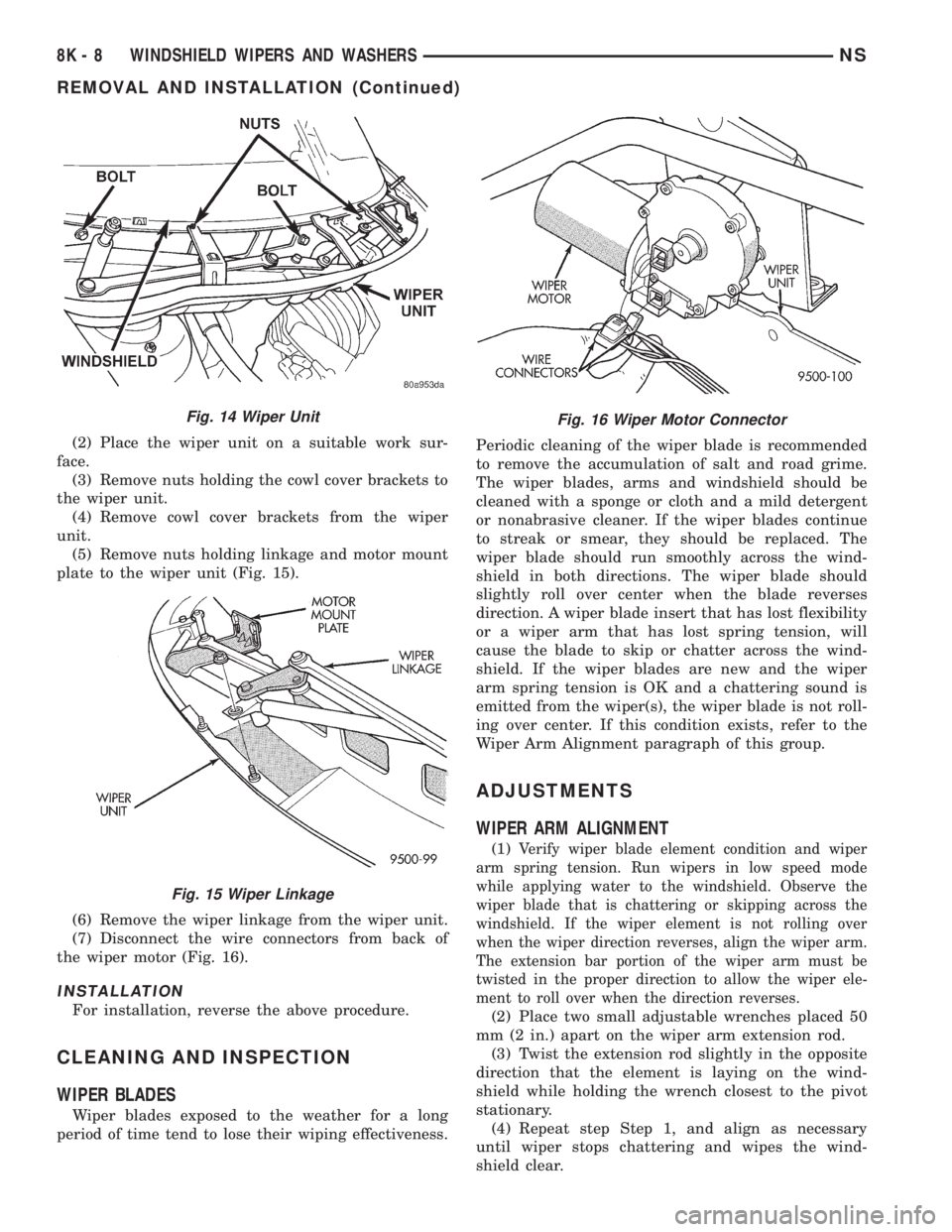
(2) Place the wiper unit on a suitable work sur-
face.
(3) Remove nuts holding the cowl cover brackets to
the wiper unit.
(4) Remove cowl cover brackets from the wiper
unit.
(5) Remove nuts holding linkage and motor mount
plate to the wiper unit (Fig. 15).
(6) Remove the wiper linkage from the wiper unit.
(7) Disconnect the wire connectors from back of
the wiper motor (Fig. 16).
INSTALLATION
For installation, reverse the above procedure.
CLEANING AND INSPECTION
WIPER BLADES
Wiper blades exposed to the weather for a long
period of time tend to lose their wiping effectiveness.Periodic cleaning of the wiper blade is recommended
to remove the accumulation of salt and road grime.
The wiper blades, arms and windshield should be
cleaned with a sponge or cloth and a mild detergent
or nonabrasive cleaner. If the wiper blades continue
to streak or smear, they should be replaced. The
wiper blade should run smoothly across the wind-
shield in both directions. The wiper blade should
slightly roll over center when the blade reverses
direction. A wiper blade insert that has lost flexibility
or a wiper arm that has lost spring tension, will
cause the blade to skip or chatter across the wind-
shield. If the wiper blades are new and the wiper
arm spring tension is OK and a chattering sound is
emitted from the wiper(s), the wiper blade is not roll-
ing over center. If this condition exists, refer to the
Wiper Arm Alignment paragraph of this group.
ADJUSTMENTS
WIPER ARM ALIGNMENT
(1)Verify wiper blade element condition and wiper
arm spring tension. Run wipers in low speed mode
while applying water to the windshield. Observe the
wiper blade that is chattering or skipping across the
windshield. If the wiper element is not rolling over
when the wiper direction reverses, align the wiper arm.
The extension bar portion of the wiper arm must be
twisted in the proper direction to allow the wiper ele-
ment to roll over when the direction reverses.
(2) Place two small adjustable wrenches placed 50
mm (2 in.) apart on the wiper arm extension rod.
(3) Twist the extension rod slightly in the opposite
direction that the element is laying on the wind-
shield while holding the wrench closest to the pivot
stationary.
(4) Repeat step Step 1, and align as necessary
until wiper stops chattering and wipes the wind-
shield clear.
Fig. 14 Wiper Unit
Fig. 15 Wiper Linkage
Fig. 16 Wiper Motor Connector
8K - 8 WINDSHIELD WIPERS AND WASHERSNS
REMOVAL AND INSTALLATION (Continued)
Page 449 of 1938
REAR WIPER AND WASHER
INDEX
page page
DESCRIPTION AND OPERATION
INTRODUCTION......................... 9
REAR WINDOW WIPER/WASHER SWITCHES . . . 9
DIAGNOSIS AND TESTING
DIAGNOSTIC PROCEDURES................ 9
REMOVAL AND INSTALLATION
REAR GLASS RUBBER GROMMET........... 9REAR WINDOW WIPER MOTOR............ 10
REAR WIPER ARM...................... 10
REAR WIPER BLADE ELEMENT............ 10
REAR WIPER BLADE..................... 10
DESCRIPTION AND OPERATION
INTRODUCTION
When continuous rear wiper operation is required,
the Body Control Module (BCM) will provide ignition
ON voltage to the rear wiper motor. When the wiper
switch is turned OFF, the BCM provides circuit
ground to operate the motor until the wipe cycle is
complete and the wiper arm returns to the base of
the rear window.
When intermittent rear wiper mode is selected, the
wiper motor will cycle every 7 seconds. The intermit-
tent delay time is also adjusted based upon vehicle
speed. With the vehicle traveling greater at 50 mph,
the cycle changes to every 5 seconds.
REAR WINDOW WIPER/WASHER SWITCHES
The rear window wiper/washer switches are incor-
porated into the HVAC switch panel. Refer to Group
8E, Instrument Panel for proper service procedures.
DIAGNOSIS AND TESTING
DIAGNOSTIC PROCEDURES
The rear window wiper system operates in several
modes:
²Continuous wipe
²Intermittent wipe
²Wash
²Wipe after wash
The windshield wiper circuits are continuously
monitored and controlled by the Body Control Mod-
ule (BCM). If a problem occurs in the electronic com-
ponents, wiring, switch (except integral motor park
switch) and wiper motor a Diagnostic Trouble Code
(DTC) will be stored in the BCM memory. The
DTC(s) can be retrieved using a scan tool (DRB).
Refer to proper Body Diagnostic Procedures manual
for DTC descriptions and retrieval information.
REMOVAL AND INSTALLATION
REAR GLASS RUBBER GROMMET
REMOVAL
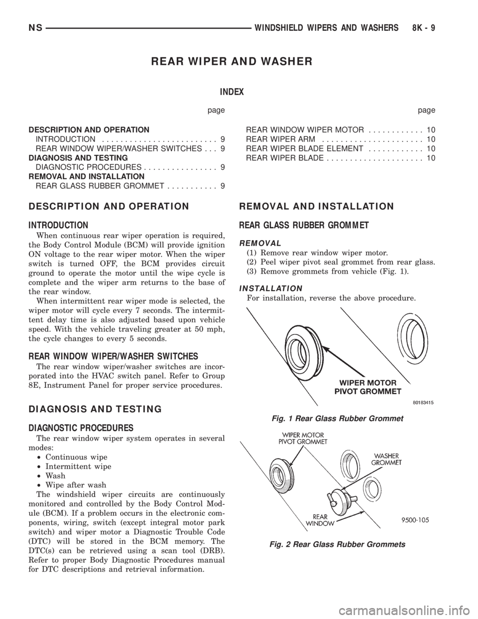
(1) Remove rear window wiper motor.
(2) Peel wiper pivot seal grommet from rear glass.
(3) Remove grommets from vehicle (Fig. 1).
INSTALLATION
For installation, reverse the above procedure.
Fig. 1 Rear Glass Rubber Grommet
Fig. 2 Rear Glass Rubber Grommets
NSWINDSHIELD WIPERS AND WASHERS 8K - 9
Page 454 of 1938

ning light functions (for Canadian vehicles), and has
been designed with internal relays to take advantage
of low current switching requirements in the vehicle.
It is plugged into the junction block at positions
three and four (Fig. 1), where all wiring associated
with its operation is terminated. The junction block
is adjacent to and left of the steering column of the
vehicle. For diagnostic information refer to Group 8J,
Turn Signal and Flashers.
On vehicles built for use in the United States, only
position four is used. Vehicles built for use in Canada
utilize both positions three and four.
To gain access to the device, remove the lower
steering column cover and knee blocker. Refer to
Group 8E, Instrument Panel and Gauges.SYSTEM FUNCTION
The combination-flasher/DRL may be operated in
its hazard warning mode either with or without the
ignition circuit being active. However, in order to
operate in the turn signal mode or the DRL mode,
the ignition circuit must be completed to the module.
While the combination-flasher portion is idle, there
is no current drawn through the module. The device
does not become active in the turn signal or hazard
warning modes until a signal ground circuit is sup-
plied to either of the turn signal inputs or the hazard
warning input. With the ignition OFF, there is no
current drawn through the module.
While the ignition is ON, the front turn signal fil-
aments are illuminated steadily thus providing the
DRL function. The DRL function may be inhibited by
applying a signal ground input from either the park
brake circuit or the headlamp relay activation circuit.
DIAGNOSIS AND TESTING
DIAGNOSTIC PROCEDURES
When a vehicle experiences problems with the
headlamp system, verify the condition of the battery
connections, charging system, headlamp bulbs, wire
connectors, relay, high beam dimmer switch and
headlamp switch. Refer to Group 8W, Wiring Dia-
grams, for component locations and circuit informa-
tion.
Fig. 1 Junction Block Terminal PINS
8L - 2 LAMPSNS
GENERAL INFORMATION (Continued)
Page 499 of 1938

SERVICE PROCEDURES
CLEANUP PROCEDURE
Roll or fold the passenger airbag towards the
instrument panel surface and close the door over the
folded bag. Then tape the door shut.
Use a vacuum cleaner to remove any residual pow-
der from the vehicle interior. Work from the outside
in to avoid kneeling or sitting in a contaminated
area. Vacuum the heater and A/C outlets as well (Fig.
2). If HVAC was in RECIRC mode at time of airbag
deployment, operate HVAC blower on low speed/heat
and vacuum powder residue expelled from the heat
outlets. Multiple vacuum cleaning may to necessary
to decontaminate the interior of the vehicle.
NOTE: Dispose deployed airbag properly, contact
dealer or government agency for disposal recom-
mendations.
SERVICE OF DEPLOYED AIRBAG MODULE
DRIVER AIRBAG
If a Driver Airbag Module has been deployed, but
not due to a collision, replace the following:
²Driver Airbag Module
²Clockspring assembly
²Driver airbag cover/horn switch
The components above must be replaced because
they cannot be reused. Replace any other driver air-
bag system components if damaged.
PASSENGER AIRBAG
If a Passenger Airbag Module has been deployed,
but not due to a collision, replace the following:
²Passenger Airbag Module
²Upper instrument panel with pad
The component above must be replaced because
they cannot be reused. Inspect the heat duct near the
passenger airbag for any damage replace as neces-sary. Replace any other passenger airbag system
components if damaged.
HANDLING AIRBAG MODULE
DEPLOYED MODULE
The vehicle interior may contain a very small
amount of sodium hydroxide powder, a by-product of
airbag deployment. Sodium hydroxide powder can
irritate the skin, eyes, nose and throat. Wear safety
glasses, rubber gloves, and long sleeved clothing
when cleaning any of the powder residue from the
vehicle.
If you find that the cleanup is irritating your skin,
run cool water over the affected area. Also, if you
experience nasal or throat irritation, exit the vehicle
for fresh air until the irritation ceases. If irritation
continues, see a physician.
UNDEPLOYED
The airbag modules must be stored in its original
special container until used for service. At no time
should a source of electricity be permitted near the
inflator on the back of an airbag module. When car-
rying or handling an undeployed airbag module, the
trim side of the airbag should be pointing away from
the body to minimize possibility of injury if acciden-
tal deployment occurs. Do not place undeployed air-
bag face down on a solid surface, the airbag will
propel into the air if accidentally deployment occurs.
REMOVAL AND INSTALLATION
AIRBAG CONTROL MODULE
WARNING: THE ACM CONTAINS THE IMPACT
SENSOR WHICH ENABLES THE SYSTEM TO
DEPLOY THE AIRBAGS. TO AVOID ACCIDENTAL
DEPLOYMENT, NEVER CONNECT ACM ELECTRI-
CALLY TO THE SYSTEM WHILE VEHICLE BATTERY
IS CONNECTED. DISCONNECT AND ISOLATE THE
BATTERY NEGATIVE CABLE BEFORE BEGINNING
ANY AIRBAG SYSTEM COMPONENT SERVICE PRO-
CEDURES. THIS WILL DISABLE THE AIRBAG SYS-
TEM. FAILURE TO DISCONNECT THE BATTERY
COULD RESULT IN ACCIDENTAL AIRBAG DEPLOY-
MENT AND POSSIBLE PERSONAL INJURY. ALLOW
SYSTEM CAPACITOR TO DISCHARGE FOR TWO
MINUTES BEFORE REMOVING AIRBAG COMPO-
NENTS.
REMOVAL
(1) Disconnect and isolate battery negative cable.
Allow at least two minutes for the reserve capacitor
in the Airbag Control Module (ACM) to discharge.
Fig. 2 Vacuum Heater and A/C Outlets
NSRESTRAINT SYSTEM 8M - 3
Page 505 of 1938
ELECTRICALLY HEATED SYSTEMS
CONTENTS
page page
DESCRIPTION AND OPERATION
HVAC MOUNTED SWITCH................. 1
INTRODUCTION......................... 1
DIAGNOSIS AND TESTING
GRID LINE TEST......................... 2SYSTEM TEST.......................... 2
SERVICE PROCEDURES
GRID LINE AND TERMINAL REPAIR......... 3
DESCRIPTION AND OPERATION
INTRODUCTION
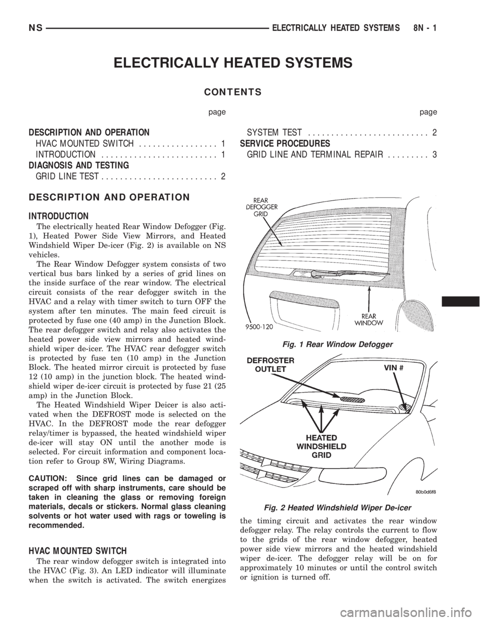
The electrically heated Rear Window Defogger (Fig.
1), Heated Power Side View Mirrors, and Heated
Windshield Wiper De-icer (Fig. 2) is available on NS
vehicles.
The Rear Window Defogger system consists of two
vertical bus bars linked by a series of grid lines on
the inside surface of the rear window. The electrical
circuit consists of the rear defogger switch in the
HVAC and a relay with timer switch to turn OFF the
system after ten minutes. The main feed circuit is
protected by fuse one (40 amp) in the Junction Block.
The rear defogger switch and relay also activates the
heated power side view mirrors and heated wind-
shield wiper de-icer. The HVAC rear defogger switch
is protected by fuse ten (10 amp) in the Junction
Block. The heated mirror circuit is protected by fuse
12 (10 amp) in the junction block. The heated wind-
shield wiper de-icer circuit is protected by fuse 21 (25
amp) in the Junction Block.
The Heated Windshield Wiper Deicer is also acti-
vated when the DEFROST mode is selected on the
HVAC. In the DEFROST mode the rear defogger
relay/timer is bypassed, the heated windshield wiper
de-icer will stay ON until the another mode is
selected. For circuit information and component loca-
tion refer to Group 8W, Wiring Diagrams.
CAUTION: Since grid lines can be damaged or
scraped off with sharp instruments, care should be
taken in cleaning the glass or removing foreign
materials, decals or stickers. Normal glass cleaning
solvents or hot water used with rags or toweling is
recommended.
HVAC MOUNTED SWITCH
The rear window defogger switch is integrated into
the HVAC (Fig. 3). An LED indicator will illuminate
when the switch is activated. The switch energizesthe timing circuit and activates the rear window
defogger relay. The relay controls the current to flow
to the grids of the rear window defogger, heated
power side view mirrors and the heated windshield
wiper de-icer. The defogger relay will be on for
approximately 10 minutes or until the control switch
or ignition is turned off.
Fig. 1 Rear Window Defogger
Fig. 2 Heated Windshield Wiper De-icer
NSELECTRICALLY HEATED SYSTEMS 8N - 1
Page 514 of 1938
SERVICE PROCEDURES
HORN CHIRP DISABLE OR ENABLE
The horn chirp can be DISABLED or ENABLED
using the following procedure.
To DISABLE (cancelling) the horn chirp feature,
press and hold the transmitter LOCK button for a
minimum four seconds. While pressing LOCK button
in, press the UNLOCK button. The horn chirp fea-
ture will not function until the above procedure is
repeated. To ENABLE (reinstate) the horn chirp fea-
ture, use any one of the four key fob transmitters
and reverse the above procedures. It will ENABLE
the horn chirp feature for all transmitters.
REMOVAL AND INSTALLATION
RKE MODULE
REMOVAL
(1) Remove instrument panel top cover. Refer to
Group 8E, Instrument Panel and Gauges for proper
procedures.
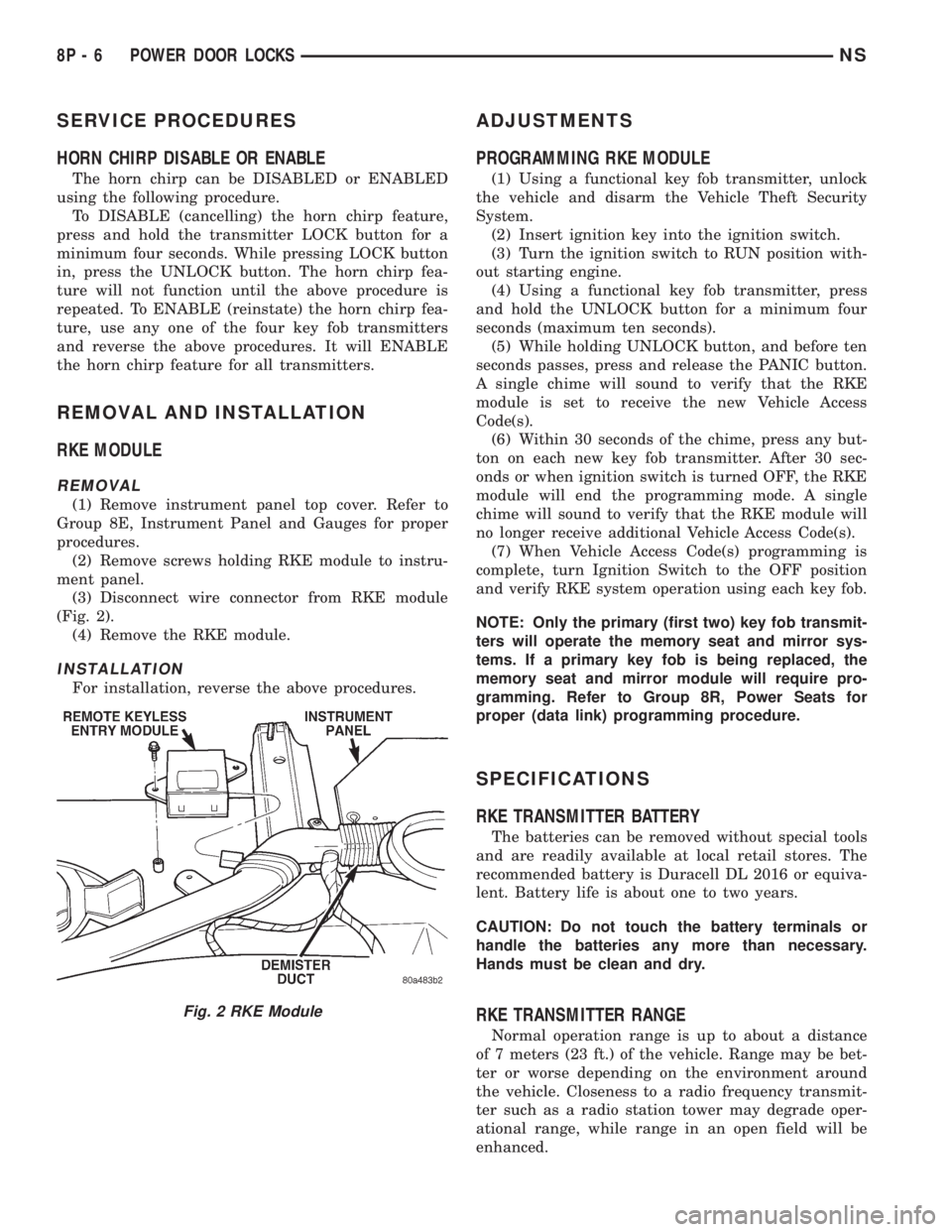
(2) Remove screws holding RKE module to instru-
ment panel.
(3) Disconnect wire connector from RKE module
(Fig. 2).
(4) Remove the RKE module.
INSTALLATION
For installation, reverse the above procedures.
ADJUSTMENTS
PROGRAMMING RKE MODULE
(1) Using a functional key fob transmitter, unlock
the vehicle and disarm the Vehicle Theft Security
System.
(2) Insert ignition key into the ignition switch.
(3) Turn the ignition switch to RUN position with-
out starting engine.
(4) Using a functional key fob transmitter, press
and hold the UNLOCK button for a minimum four
seconds (maximum ten seconds).
(5) While holding UNLOCK button, and before ten
seconds passes, press and release the PANIC button.
A single chime will sound to verify that the RKE
module is set to receive the new Vehicle Access
Code(s).
(6) Within 30 seconds of the chime, press any but-
ton on each new key fob transmitter. After 30 sec-
onds or when ignition switch is turned OFF, the RKE
module will end the programming mode. A single
chime will sound to verify that the RKE module will
no longer receive additional Vehicle Access Code(s).
(7) When Vehicle Access Code(s) programming is
complete, turn Ignition Switch to the OFF position
and verify RKE system operation using each key fob.
NOTE: Only the primary (first two) key fob transmit-
ters will operate the memory seat and mirror sys-
tems. If a primary key fob is being replaced, the
memory seat and mirror module will require pro-
gramming. Refer to Group 8R, Power Seats for
proper (data link) programming procedure.
SPECIFICATIONS
RKE TRANSMITTER BATTERY
The batteries can be removed without special tools
and are readily available at local retail stores. The
recommended battery is Duracell DL 2016 or equiva-
lent. Battery life is about one to two years.
CAUTION: Do not touch the battery terminals or
handle the batteries any more than necessary.
Hands must be clean and dry.
RKE TRANSMITTER RANGE
Normal operation range is up to about a distance
of 7 meters (23 ft.) of the vehicle. Range may be bet-
ter or worse depending on the environment around
the vehicle. Closeness to a radio frequency transmit-
ter such as a radio station tower may degrade oper-
ational range, while range in an open field will be
enhanced.
Fig. 2 RKE Module
8P - 6 POWER DOOR LOCKSNS
Page 515 of 1938
VEHICLE THEFT SECURITY SYSTEM
CONTENTS
page page
GENERAL INFORMATION
INTRODUCTION......................... 1
DESCRIPTION AND OPERATION
ARMING PROCEDURE.................... 1
TIME-OUT PERIOD....................... 2
TRIGGERING THE VTSS................... 2
DIAGNOSIS AND TESTING
DIAGNOSTIC PROCEDURES................ 2
REMOVAL AND INSTALLATION
BODY CONTROL MODULE................. 2DOOR LOCK CYLINDER SWITCH............ 2
FRONT DOOR AJAR (VTSS TRIGGER)
SWITCH.............................. 2
HOOD AJAR (VTSS TRIGGER) SWITCH...... 3
LIFTGATE AJAR (VTSS TRIGGER) SWITCH.... 3
LIFTGATE LOCK CYLINDER SWITCH......... 3
SLIDING DOOR AJAR (VTSS TRIGGER)
SWITCH.............................. 4
GENERAL INFORMATION
INTRODUCTION
Vehicles equipped with the Vehicle Theft Security
System (VTSS) system, the doors, liftgate, hood and
ignition circuit are monitored by the Body Control
Module (BCM) when the system is armed. The VTSS
will prevent the engine from starting until the BCM
receives a disarm signal. If the VTSS is triggered,
the horn will pulse, headlamps/marker lamps will
flash, and the VTSS warning lamp will flash. If BCM
determines the threat to be false and the VTSS is not
triggered again, the system will shut down and
rearm itself after three minutes. The VTSS monitor-
ing portion of the system is split into two sections.
The engine compartment section and the passenger
compartment section. If a malfunction occurs in the
engine compartment section, the passenger compart-
ment section would still arm and function normally.
If an electrical malfunction occurs in either section of
the system a Diagnostic Trouble Code (DTC) would
be stored the BCM memory to aid system repair.
DTCs can be retrieved using scan tool (DRB)
attached to the diagnostic connector above the accel-
erator pedal.
ENABLING
To initialize the VTSS feature the operator must,
with the engine compartment hood open, cycle the
key in the liftgate key cylinder to the unlock position
giving the BCM a disarm signal. At this time the
visual alarm outputs the headlamps and marker
lamps will function. However the audio alarm output
the horn and engine disable portion of the VTSS will
not function until there has been twenty consecutiveengine run cycles. When this has occurred the total
VTSS will function.
If during alarm being set the BCM receives a
request from the RKE module to enter PANIC mode
the BCM will cancel the alarm, return VTSS armed
state and then perform the RKE PANIC feature.
DESCRIPTION AND OPERATION
ARMING PROCEDURE
METHOD-A
(1) With the key removed from the ignition lock
and any door open, actuate one of the following:
²Power door lock button to LOCK,
²Key fob LOCK button
²Door lock key cylinder to locked position.
(2) Close all opened doors.
(3) After the last door is closed, an arming time-
out period of sixteen seconds will start, then the
VTSS will become armed.
METHOD-B
Actuating the key fob transmitter LOCK button,
key locking the front doors or liftgate with the doors
closed and the ignition locked will begin the arming
time-out period. If method-A, 16 second time-out
sequence was in process when method-B was actu-
ated, the 16 second time-out will restart from the
time of the second actuation.
If the security lamp does not illuminate at all upon
final door closure, it indicates that the system is not
arming.
The current VTSS status armed or disarmed shall
be maintained in memory to prevent battery discon-
nects from disarming the system.
NSVEHICLE THEFT SECURITY SYSTEM 8Q - 1