ECO mode CHRYSLER VOYAGER 1996 Owner's Guide
[x] Cancel search | Manufacturer: CHRYSLER, Model Year: 1996, Model line: VOYAGER, Model: CHRYSLER VOYAGER 1996Pages: 1938, PDF Size: 55.84 MB
Page 1182 of 1938
(4) If oil pressure is 0 at idle. Shut off engine,
check for pressure relief valve stuck open, a clogged
oil pick-up screen or a damaged oil pick-up tube
O-ring.
SERVICE PROCEDURES
CYLINDER BORE AND PISTON SIZING
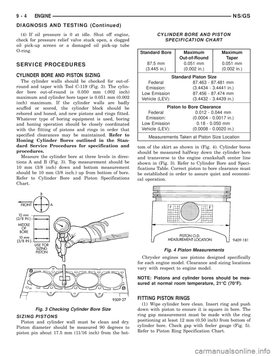
The cylinder walls should be checked for out-of-
round and taper with Tool C-119 (Fig. 3). The cylin-
der bore out-of-round is 0.050 mm (.002 inch)
maximum and cylinder bore taper is 0.051 mm (0.002
inch) maximum. If the cylinder walls are badly
scuffed or scored, the cylinder block should be
rebored and honed, and new pistons and rings fitted.
Whatever type of boring equipment is used, boring
and honing operation should be closely coordinated
with the fitting of pistons and rings in order that
specified clearances may be maintained.Refer to
Honing Cylinder Bores outlined in the Stan-
dard Service Procedures for specification and
procedures.
Measure the cylinder bore at three levels in direc-
tions A and B (Fig. 3). Top measurement should be
10 mm (3/8 inch) down and bottom measurement
should be 10 mm (3/8 inch.) up from bottom of bore.
Refer to Cylinder Bore and Piston Specifications
Chart.
SIZING PISTONS
Piston and cylinder wall must be clean and dry.
Piston diameter should be measured 90 degrees to
piston pin about 17.5 mm (11/16 inch) from the bot-tom of the skirt as shown in (Fig. 4). Cylinder bores
should be measured halfway down the cylinder bore
and transverse to the engine crankshaft center line
shown in (Fig. 3). Refer to Cylinder Bore and Speci-
fications Table. Correct piston to bore clearance must
be established in order to assure quiet and economi-
cal operation.
Chrysler engines use pistons designed specifically
for each engine model. Clearance and sizing locations
vary with respect to engine model.
NOTE: Pistons and cylinder bores should be mea-
sured at normal room temperature, 21ÉC (70ÉF).
FITTING PISTON RINGS
(1) Wipe cylinder bore clean. Insert ring and push
down with piston to ensure it is square in bore. The
ring gap measurement must be made with the ring
positioning at least 12 mm (0.50 inch) from bottom of
cylinder bore. Check gap with feeler gauge (Fig. 5).
Refer to Piston Ring Specification Chart.
Fig. 3 Checking Cylinder Bore Size
CYLINDER BORE AND PISTON
SPECIFICATION CHART
Standard Bore Maximum
Out-of-RoundMaximum
Taper
87.5 mm
(3.445 in.)0.051 mm
(0.002 in.)0.051 mm
(0.002 in.)
Standard Piston Size
Federal
Emission:87.463 - 87.481 mm
(3.4434 - 3.4441 in.)
Low Emission
Vehicle (LEV):87.456 - 87.474 mm
(3.4432 - 3.4439 in.)
Piston to Bore Clearance
Federal
Emission:0.012 - 0.044 mm
(0.0004 - 0.0017 in.)
Low Emission
Vehicle (LEV):0.18 - 0.050 mm
(0.0008 - 0.0020 in.)
Measurements Taken at Piston Size Location
Fig. 4 Piston Measurements
9 - 4 ENGINENS/GS
DIAGNOSIS AND TESTING (Continued)
Page 1324 of 1938
THROTTLE BODY....................... 64
THROTTLE POSITION SENSOR............ 65
UPSTREAM OXYGEN SENSOR............. 68
SPECIFICATIONS
TORQUE.............................. 72SPECIAL TOOLS
FUEL................................. 72
GENERAL INFORMATION
INTRODUCTION
All engines used in this section have a sequential
Multi-Port Electronic Fuel Injection system. The MPI
system is computer regulated and provides precise
air/fuel ratios for all driving conditions. The Power-
train Control Module (PCM) operates the fuel injec-
tion system.
The PCM regulates:
²Ignition timing
²Air/fuel ratio
²Emission control devices
²Cooling fan
²Charging system
²Idle speed
²Vehicle speed control
Various sensors provide the inputs necessary for
the PCM to correctly operate these systems. In addi-
tion to the sensors, various switches also provide
inputs to the PCM.
All inputs to the PCM are converted into signals.
The PCM can adapt its programming to meet chang-
ing operating conditions.
Fuel is injected into the intake port above the
intake valve in precise metered amounts through
electrically operated injectors. The PCM fires the
injectors in a specific sequence. Under most operat-
ing conditions, the PCM maintains an air fuel ratio
of 14.7 parts air to 1 part fuel by constantly adjust-
ing injector pulse width. Injector pulse width is the
length of time the injector is open.
The PCM adjusts injector pulse width by opening
and closing the ground path to the injector. Engine
RPM (speed) and manifold absolute pressure (air
density) are the primary inputs that determine injec-
tor pulse width.
MODES OF OPERATION
As input signals to the PCM change, the PCM
adjusts its response to output devices. For example,
the PCM must calculate a different injector pulse
width and ignition timing for idle than it does for
Wide Open Throttle (WOT). There are several differ-
ent modes of operation that determine how the PCM
responds to the various input signals.
There are two different areas of operation, OPEN
LOOP and CLOSED LOOP.
During OPEN LOOP modes the PCM receives
input signals and responds according to preset PCMprogramming. Input from the oxygen (O2S) sensor is
not monitored during OPEN LOOP modes.
During CLOSED LOOP modes the PCM does mon-
itor the O2S sensor input. This input indicates to the
PCM whether or not the calculated injector pulse
width results in the ideal air/fuel ratio of 14.7 parts
air to 1 part fuel. By monitoring the exhaust oxygen
content through the O2S sensor, the PCM can fine
tune the injector pulse width. Fine tuning injector
pulse width allows the PCM to achieve optimum fuel
economy combined with low emissions.
The multi-port fuel injection system has the follow-
ing modes of operation:
²Ignition switch ON (zero RPM)
²Engine start-up
²Engine warm-up
²Cruise (Idle)
²Acceleration
²Deceleration
²Wide Open Throttle
²Ignition switch OFF
The engine start-up (crank), engine warm-up, and
wide open throttle modes are OPEN LOOP modes.
Under most operating conditions, the acceleration,
deceleration, and cruise modes,with the engine at
operating temperatureare CLOSED LOOP modes.
IGNITION SWITCH ON (ZERO RPM) MODE
When the multi-port fuel injection system is acti-
vated by the ignition switch, the following actions
occur:
²The PCM determines atmospheric air pressure
from the MAP sensor input to determine basic fuel
strategy.
²The PCM monitors the coolant temperature sen-
sor and throttle position sensor input. The PCM mod-
ifies fuel strategy based on this input.
When the key is in the ON position and the engine
is not running (zero rpm), the Automatic Shutdown
(ASD) relay and fuel pump relay are not energized.
Therefore battery voltage is not supplied to the fuel
pump, ignition coil, fuel injectors or oxygen sensor
heating element.
ENGINE START-UP MODE
This is an OPEN LOOP mode. The following
actions occur when the starter motor is engaged.
If the PCM receives the camshaft position sensor
and crankshaft position sensor signals, it energizes
the ASD relay and fuel pump relay. These relays sup-
ply battery voltage to the fuel pump, fuel injectors,
14 - 30 FUEL SYSTEMNS
SPECIFICATIONS (Continued)
Page 1325 of 1938
ignition coil, and oxygen sensor heating element. If
the PCM does not receive the camshaft position sen-
sor and crankshaft position sensor signals within
approximately one second, it de-energizes the ASD
relay and fuel pump relay.
The PCM energizes all injectors until it determines
crankshaft position from the camshaft position sen-
sor and crankshaft position sensor signals. The PCM
determines crankshaft position within 1 engine revo-
lution.
After determining crankshaft position, the PCM
begins energizing the injectors in sequence. The PCM
adjusts injector pulse width and controls injector syn-
chronization by turning the individual ground paths
to the injectors On and Off.
When the engine idles within664 RPM of its tar-
get RPM, the PCM compares current MAP sensor
value with the atmospheric pressure value received
during the Ignition Switch On (zero RPM) mode. If
the PCM does not detect a minimum difference
between the two values, it sets a MAP diagnostic
trouble code into memory.
Once the ASD and fuel pump relays have been
energized, the PCM:
²Determines injector pulse width based on engine
coolant temperature, MAP and the number of engine
revolutions since cranking was initiated.
²Monitors the engine coolant temperature sensor,
camshaft position sensor, crankshaft position sensor,
MAP sensor, and throttle position sensor to deter-
mine correct ignition timing.
ENGINE WARM-UP MODE
This is a OPEN LOOP mode. The following inputs
are received by the PCM:
²Engine coolant temperature
²Manifold absolute pressure
²Engine speed (crankshaft position sensor)
²Throttle position
²A/C switch
²Battery voltage
The PCM adjusts injector pulse width and controls
injector synchronization by turning the individual
ground paths to the injectors On and Off.
The PCM adjusts ignition timing and engine idle
speed. Engine idle speed is adjusted through the idle
air control motor.
CRUISE OR IDLE MODE
This is a CLOSED LOOP mode. The PCM recog-
nizes an abrupt increase in throttle position or MAP
pressure as a demand for increased engine output
and vehicle acceleration. The PCM increases injector
pulse width in response to increased fuel demand.
When the engine is at operating temperature this
is a CLOSED LOOP mode. During cruising speed the
following inputs are received by the PCM:²Engine coolant temperature
²Manifold absolute pressure
²Engine speed (crankshaft position sensor)
²Throttle position
²Exhaust gas oxygen content
²A/C control positions
²Battery voltage
The PCM adjusts injector pulse width and controls
injector synchronization by turning the individual
ground paths to the injectors On and Off.
The PCM adjusts engine idle speed and ignition
timing. The PCM adjusts the air/fuel ratio according
to the oxygen content in the exhaust gas.
ACCELERATION MODE
This is a CLOSED LOOP mode. The PCM recog-
nizes an abrupt increase in throttle position or MAP
pressure as a demand for increased engine output
and vehicle acceleration. The PCM increases injector
pulse width in response to increased fuel demand.
DECELERATION MODE
This is a CLOSED LOOP mode. During decelera-
tion the following inputs are received by the PCM:
²Engine coolant temperature
²Manifold absolute pressure
²Engine speed
²Throttle position
²Exhaust gas oxygen content
²A/C control positions
²Battery voltage
The PCM may receive a closed throttle input from
the Throttle Position Sensor (TPS) when it senses an
abrupt decrease in manifold pressure. This indicates
a hard deceleration. The PCM may reduce injector
pulse width or the number of injectors firing per
engine revolution. This helps maintain better control
of the air/fuel mixture (as sensed through the O2S
sensor).
WIDE OPEN THROTTLE (WOT) MODE
This is an OPEN LOOP mode. During WOT oper-
ation, the following inputs are received by the PCM:
²Engine coolant temperature
²Manifold absolute pressure
²Engine speed
²Throttle position
When the PCM senses WOT condition through the
Throttle Position Sensor (TPS) it will:
²De-energize the air conditioning relay. This dis-
ables the air conditioning system.
The exhaust gas oxygen content input is not
accepted by the PCM during WOT operation. The
PCM will adjust injector pulse width to supply a pre-
determined amount of additional fuel.
NSFUEL SYSTEM 14 - 31
GENERAL INFORMATION (Continued)
Page 1340 of 1938
Shutdown (ASD) RelayÐPCM Output in this section
for relay operation.
TORQUE CONVERTER CLUTCH SOLENOIDÐPCM
OUTPUT
Three-speed automatic transaxles use a torque con-
verter clutch solenoid. The PCM controls the engage-
ment of the torque converter clutch through the
solenoid. The torque converter clutch is engaged only
in direct drive mode. Refer to Group 21 for transaxle
information.
MALFUNCTION INDICATOR (CHECK ENGINE)
LAMPÐPCM OUTPUT
The PCM supplies the malfunction indicator (check
engine) lamp on/off signal to the instrument panel
through the CCD Bus. The CCD Bus is a communi-
cations port. Various modules use the CCD Bus to
exchange information.
The Check Engine lamp comes on each time the
ignition key is turned ON and stays on for 3 seconds
as a bulb test.
The Malfunction Indicator Lamp (MIL) stays on
continuously, when the PCM has entered a Limp-In
mode or identified a failed emission component. Dur-
ing Limp-in Mode, the PCM attempts to keep the
system operational. The MIL signals the need for
immediate service. In limp-in mode, the PCM com-
pensates for the failure of certain components that
send incorrect signals. The PCM substitutes for the
incorrect signals with inputs from other sensors.
If the PCM detects active engine misfire severe
enough to cause catalyst damage, it flashes the MIL.
At the same time the PCM also sets a Diagnostic
Trouble Code (DTC).
For signals that can trigger the MIL (Check
Engine Lamp) refer to Group 25, On-Board
Dianostics.
SOLID STATE FAN RELAYÐPCM OUTPUT
The radiator fan runs at a variable speed depend-
ing on coolant temperature and A/C system pressure.
The radiator fan circuit contains a Solid State Fan
Relay (SSFR). Refer to the Group 8W for a circuit
schematic.
A 5 volt signal is supplied to the SSFR. The PCM
provides a pulsed ground for the SSFR. Depending
upon the amount of pulse on time, the SSFR puts out
a proportional voltage to the fan motor at the lower
speed. For instance, if the on time is 30 percent, then
the voltage to the fan motor will be 3.6 volts.
When engine coolant reaches approximately 102ÉC
(215ÉF) the PCM grounds the SSFR relay. If engine
coolant reaches 207ÉC (225ÉF) the PCM grounds the
high speed ground relay and high speed fan relay. If
the fan operates at high speed, the PCM de-energizes
the high speed relay and high speed ground relay
when coolant temperature drops to approximately
101ÉC (214ÉF). When coolant temperature drops to
101ÉC (214ÉF) the fan operates at low speed. The
PCM de-energizes the low speed relay when coolant
temperature drops to approximately 93ÉC (199ÉF).
Also, when the air conditioning pressure switch
closes, the fan operates at high speed. The air condi-
tioning switch closes at 285 psi610 psi. When air
conditioning pressure drops approximately 40 psi, the
pressure switch opens and the fan operates at low
speed.
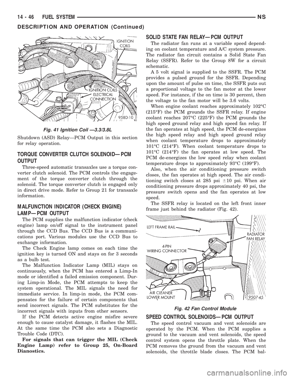
The SSFR relay is located on the left front inner
frame just behind the radiator (Fig. 42).
SPEED CONTROL SOLENOIDSÐPCM OUTPUT
The speed control vacuum and vent solenoids are
operated by the PCM. When the PCM supplies a
ground to the vacuum and vent solenoids, the speed
control system opens the throttle plate. When the
PCM removes the ground from the vacuum and vent
solenoids, the throttle blade closes. The PCM bal-
Fig. 41 Ignition Coil Ð3.3/3.8L
Fig. 42 Fan Control Module
14 - 46 FUEL SYSTEMNS
DESCRIPTION AND OPERATION (Continued)
Page 1381 of 1938
A defective fuel injection pump, defective fuel tim-
ing solenoid or misadjusted mechanical pump timing
can cause starting problems or prevent the engine
from revving up. It can also cause:
²Engine surge at idle
²Rough idle (warm engine)
²Low power
²Excessive fuel consumption
²Poor performance
²Low power
²Black smoke from the exhaust
²Blue or white fog like exhaust
²Incorrect idle or maximum speed
The electronically controlled fuel pump has no
mechanical governor like older mechanically con-
trolled fuel pumps. Do not remove the top cover of
the fuel pump, or the screws fastening the wiring
pigtail to the side of the pump.The warranty of
the injection pump and the engine may be void
if those seals have been removed or tampered
with.
FUEL SUPPLY RESTRICTIONS
LOW±PRESSURE LINES
Restricted or Plugged supply lines or fuel filter can
cause a timing fault that will cause the PCM to oper-
ate the engine in a ªLimp Homeº mode. See the
introduction of the Fuel Injection System in this
group for more information on the Limp Home mode.
Fuel supply line restrictions can cause starting prob-
lems and prevent the engine from revving up. The
starting problems include; low power and blue or
white fog like exhaust. Test all fuel supply lines for
restrictions or blockage. Flush or replace as neces-
sary. Bleed the fuel system of air once a fuel supply
line has been replaced. Refer to the Air Bleed Proce-
dure section of this group for procedures.
HIGH±PRESSURE LINES
Restricted (kinked or bent) high±pressure lines can
cause starting problems, poor engine performance
and black smoke from exhaust.
Examine all high±pressure lines for any damage.
Each radius on each high±pressure line must be
smooth and free of any bends or kinks.
Replace damaged, restricted or leaking high±pres-
sure fuel lines with the correct replacement line.
CAUTION: The high±pressure fuel lines must be
clamped securely in place in the holders. The lines
cannot contact each other or other components. Do
not attempt to weld high±pressure fuel lines or to
repair lines that are damaged. Only use the recom-
mended lines when replacement of high±pressure
fuel line is necessary.
FUEL SHUTDOWN SOLENOID TEST
Since diesel fuel injection does not use spark plugs
to start combustion, the only way to stop the engine
is to cut off the fuel supply. This is done with the
Fuel Shutdown Solenoid. If the engine cranks, but
refuses to start, it may be caused by a defective fuel
shutdown solenoid.
The fuel shutdown solenoid is not controlled
or operated by the PCM.Voltage to operate the
solenoid is supplied from the ignition (key) switch.
NOTE: Although the fuel shutdown solenoid is not
operated by the PCM, if the Fuel Shutdown Solenoid
has been disconnected, and the key turned on, the
PCM will sense that the solenoid is not in the circuit,
and will switch to a ªLimp Homeº mode. After recon-
necting the solenoid, the PCM will have to be reset
by clearing the codes with the DRBIII scan tool, or
disconnecting the vehicle's battery for several min-
utes. The DRBIII scan tool is the preferred method
for resetting the PCM. Refer to the 1998 GS 2.5L Die-
sel Powertrain Diagnostic Manual for procedure.
The fuel shutdown (shut±off) solenoid is used to
electrically shut off the diesel fuel supply to the high-
±pressure fuel injection pump. The solenoid is
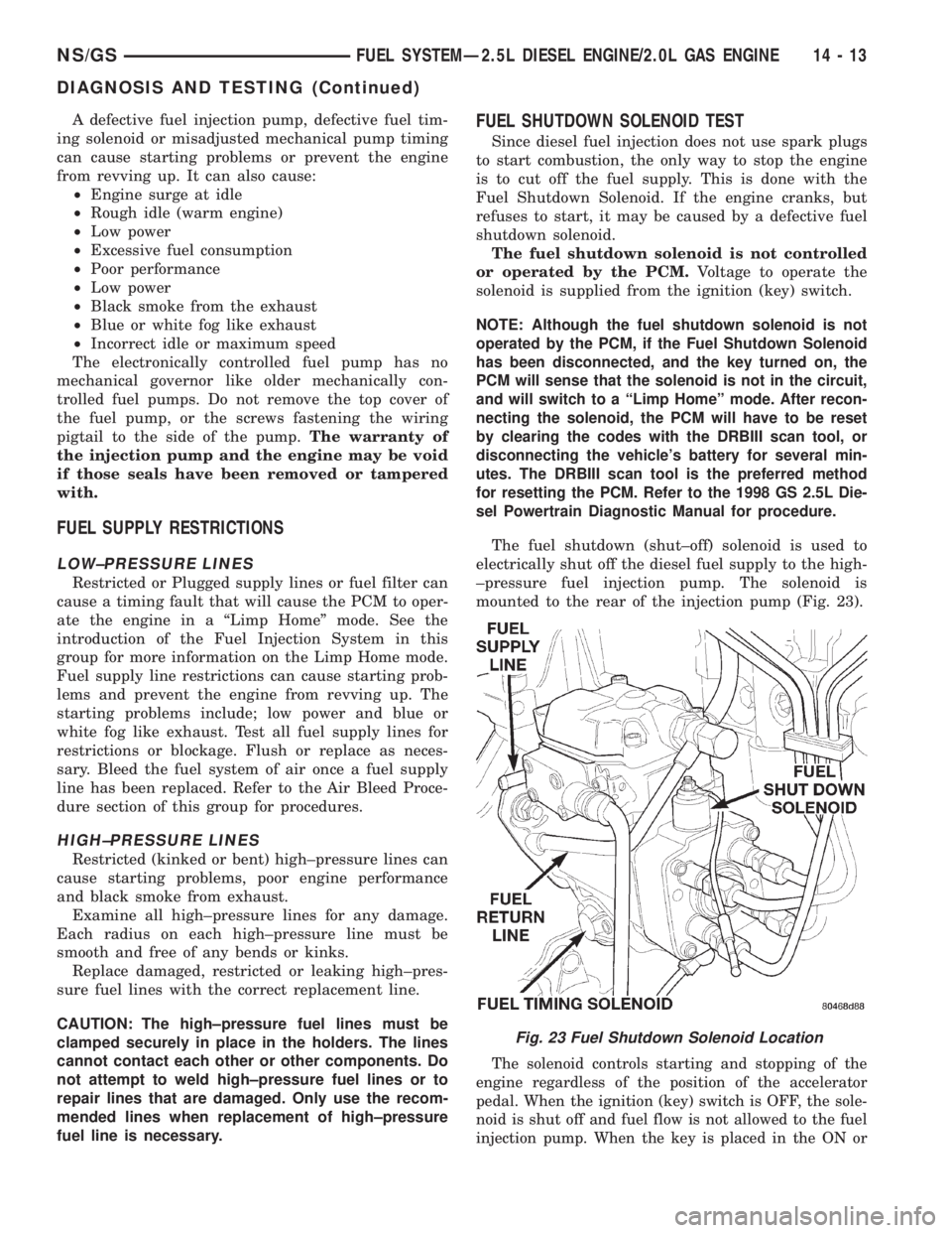
mounted to the rear of the injection pump (Fig. 23).
The solenoid controls starting and stopping of the
engine regardless of the position of the accelerator
pedal. When the ignition (key) switch is OFF, the sole-
noid is shut off and fuel flow is not allowed to the fuel
injection pump. When the key is placed in the ON or
Fig. 23 Fuel Shutdown Solenoid Location
NS/GSFUEL SYSTEMÐ2.5L DIESEL ENGINE/2.0L GAS ENGINE 14 - 13
DIAGNOSIS AND TESTING (Continued)
Page 1415 of 1938

AIR CONDITIONING (A/C) CONTROLSÐPCM
INPUTS
The A/C control system information applies to fac-
tory installed air conditioning units.
A/C REQUEST SIGNAL:When either the A/C or
Defrost mode has been selected and the A/C low and
high±pressure switches are closed, an input signal is
sent to the powertrain control module (PCM). The
PCM uses this input to cycle the A/C compressor
through the A/C relay.
If the A/C low or high±pressure switch opens, the
PCM will not receive an A/C request signal. The
PCM will then remove the ground from the A/C relay.
This will deactivate the A/C compressor clutch. Also,
if the engine coolant reaches a temperature outside
normal of its normal range, or it overheats, the PCM
will deactivate the A/C clutch.
BRAKE SWITCHÐPCM INPUT
When the brake light switch is activated, the PCM
receives an input indicating that the brakes are
being applied. After receiving this input, the PCM is
used to control the speed control system. There is a
Primary and a Secondary brake switch. The Second-
ary brake switch is closed until the brake pedal is
pressed.
DATA LINK CONNECTORÐPCM INPUT AND
OUTPUT
The 16±way data link connector (diagnostic scan
tool connector) links the Diagnostic Readout Box(DRB) scan tool with the PCM. The data link connec-
tor is located under the instrument panel near the
bottom of steering column (Fig. 7).
VEHICLE SPEED SENSORÐPCM INPUT
The vehicle speed sensor (Fig. 8) is located in the
extension housing of the transmission. The sensor
input is used by the PCM to determine vehicle speed
and distance traveled.
Fig. 6 Speed Sensor Operation
Fig. 7 Data Link Connector Location
Fig. 8 Vehicle Speed SensorÐTypical
NS/GSFUEL SYSTEMÐ2.5L DIESEL ENGINE/2.0L GAS ENGINE 14 - 47
DESCRIPTION AND OPERATION (Continued)
Page 1421 of 1938

²When the PCM energizes the Diesel PCM and
other relays, terminal 87 connects to terminal 30.
This is the On position. Terminal 87 supplies voltage
to the rest of the circuit.
TESTING
The following procedure applies to the Diesel PCM
and other relays.
(1) Remove relay from connector before testing.
(2) With the relay removed from the vehicle, use
an ohmmeter to check the resistance between termi-
nals 85 and 86. The resistance should be between 75
65 ohms.
(3) Connect the ohmmeter between terminals 30
and 87A. The ohmmeter should show continuity
between terminals 30 and 87A.
(4) Connect the ohmmeter between terminals 87
and 30. The ohmmeter should not show continuity at
this time.
(5) Connect one end of a jumper wire (16 gauge or
smaller) to relay terminal 85. Connect the other end
of the jumper wire to the ground side of a 12 volt
power source.
(6) Connect one end of another jumper wire (16
gauge or smaller) to the power side of the 12 volt
power source.Do not attach the other end of the
jumper wire to the relay at this time.
WARNING: DO NOT ALLOW OHMMETER TO CON-
TACT TERMINALS 85 OR 86 DURING THIS TEST.
(7) Attach the other end of the jumper wire to
relay terminal 86. This activates the relay. The ohm-meter should now show continuity between relay ter-
minals 87 and 30. The ohmmeter should not show
continuity between relay terminals 87A and 30.
(8) Disconnect jumper wires.
(9) Replace the relay if it did not pass the continu-
ity and resistance tests. If the relay passed the tests,
it operates properly. Check the remainder of the Die-
sel PCM and other relay circuits. Refer to group 8W,
Wiring Diagrams.
BOOST PRESSURE SENSOR
If the boost pressure sensor fails, the PCM records
a DTC into memory and continues to operate the
engine in one of the three ªlimp-inº modes. When the
PCM is operating in this mode, a loss of power will
be present, as if the turbocharger was not operating.
The best method for diagnosing faults with the boost
pressure sensor is with the DRB III scan tool.
Diagnostic Trouble Codes:Refer to On-Board
Diagnostics in Group 25, Emission Control System
for a list of Diagnostic Trouble Codes (DTC's) for cer-
tain fuel system components.
VEHICLE SPEED SENSOR TEST
To perform a test of the sensor and its related cir-
cuitry, refer to DRB scan tool.
Diagnostic Trouble Codes:Refer to On-Board
Diagnostics in Group 25, Emission Control System
for a list of Diagnostic Trouble Codes (DTC's) for cer-
tain fuel system components.
DIAGNOSTIC TROUBLE CODES
For a list of Diagnostic Trouble Codes (DTC's),
refer to Group 25, Emission Control System for infor-
mation. See On-Board Diagnostics.
REMOVAL AND INSTALLATION
DIESEL PCM RELAY
The Diesel PCM relay is located in the PDC. For
the location of the relay within the PDC, refer to
label on PDC cover.
A/C CLUTCH RELAY
The A/C clutch relay is located in the PDC. For the
location of the relay within the PDC, refer to label on
PDC cover.
ENGINE SPEED SENSOR
The engine speed sensor is mounted to the trans-
mission bellhousing at the rear of the engine block
(Fig. 18).
REMOVAL
(1) Disconnect the harness (on the sensor) from
the main electrical harness.
Fig. 17 Diesel PCM and Other Relay Terminals
NS/GSFUEL SYSTEMÐ2.5L DIESEL ENGINE/2.0L GAS ENGINE 14 - 53
DIAGNOSIS AND TESTING (Continued)
Page 1547 of 1938
CAUTION: Some clutch packs appear similar, but
they are not the same. Do not interchange clutch
components, as they might fail.
HYDRAULICS
The hydraulics of the transaxle provide:
²Manual shift lever select function
²Main line pressure regulation
²Torque converter and cooler flow control
Oil flow to the friction elements is controlled
directly by four solenoid valves. The hydraulics also
include a unique logic- controlled solenoid torque con-
verter clutch control valve. This valve locks out the
1st gear reaction element with the application of 2nd,
direct, or overdrive gear elements. It also redirects
the 1st gear solenoid output so that it can control
torque converter clutch operation. To regain access to
1st gear, a sequence of commands must be used to
move the solenoid TCC control valve. This precludes
any application of the 1st gear reaction element with
other elements applied. It also allows one solenoid to
control two friction elements.
Small, high-rate accumulators are provided in each
controlled friction element circuit. These serve to
absorb the pressure responses, and allow the controls
to read and respond to changes that are occurring.
SOLENOIDS
The solenoid valves perform most control functions,
these valves must be extremely durable and tolerant
of dirt. For that reason hardened-steel poppet and
ball valves are used. These are free from any close
operating clearances. The solenoids operate the
valves directly without any intermediate element.
Direct operation means that these units must have
very high output. They must close against the size-
able flow areas and high line pressures. Fast
response is also required to meet the control require-
ments.
Two of the solenoids are normally-venting and two
are normally-applying; this was done to provide a
default mode of operation. With no electrical power,
the transmission provides 2nd gear in (OD), (3), or
(L) shift lever positions. All other transmission lever
positions will operate normally. The choice of 2nd
gear was made to provide adequate breakaway per-
formance while still accommodating highway speeds.
SENSORS
There are three pressure switches to identify sole-
noid application. There are two speed sensors to read
input (torque converter turbine) and output (parking
sprag) speeds. There is also a transmission range
sensor to indicate the manual shift lever position.
The pressure switches are incorporated in an assem-
bly with the solenoids. Engine speed, throttle posi-tion, temperature, etc., are also observed. Some of
these signals are read directly from the engine con-
trol sensors; others are read from a multiplex circuit
with the powertrain control module.
ELECTRONICS
The 41TE Transmission Control Module (TCM) is
located underhood in a potted, die-cast aluminum
housing. The module used is a new controller called
EATX III. The TCM has a sealed, 60-way connector.
ADAPTIVE CONTROLS
These controls function by reading the input and
output speeds over 140 times a second and respond-
ing to each new reading. This provides the precise
and sophisticated friction element control needed to
make smooth clutch-to-clutch shifts for all gear
changes. The use of overrunning clutches or other
shift quality aids are not required. As with most
automatic transaxles, all shifts involve releasing one
element and applying a different element. In simpli-
fied terms, the upshift logic allows the releasing ele-
ment to slip backwards slightly. This ensures that it
does not have excess capacity. The apply element is
filled until it begins to make the speed change to the
higher gear. The apply pressure is then controlled to
maintain the desired rate of speed change. This con-
tinues until the shift is made. The key to providing
excellent shift quality is precision. For example, the
release element for upshifts is allowed to slip back-
wards slightly. The amount of that slip is typically
less than a total of 20 degrees. To achieve that pre-
cision, the TCM learns the traits of the transaxle
that it is controlling. It learns the release rate of the
releasing element and the apply time of the applying
element. It also learns the rate at which the apply
element builds pressure sufficient to begin making
the speed change. This method achieves more preci-
sion than would be possible with exacting tolerances.
It can also adapt to any changes that occur with age
or environment.
For kickdown shifts, the control logic allows the
releasing element to slip. Then controls the rate at
which the input (and engine) accelerate. When the
lower gear speed is achieved, the releasing element
reapplies to maintain that speed until the apply ele-
ment is filled. This provides quick response since the
engine begins to accelerate immediately. This also
provides a smooth torque exchange since the release
element can control the rate of torque increase. This
control can make any powertrain feel more respon-
sive without increasing harshness.
Adaptive controls respond to input speed changes.
They compensate for changes in engine or friction
element torque and provide good, consistent shift
quality for the life of the transaxle.
NSTRANSAXLE AND POWER TRANSFER UNIT 21 - 73
DESCRIPTION AND OPERATION (Continued)
Page 1658 of 1938
GENERAL INFORMATION
A-598 MANUAL TRANSAXLE
Safety goggles should be worn at all times
when working on these transaxles.The A-598
manual transaxle uses SAE 5W-30 engine oil, meet-
ing SG and/or SG-CD qualifications, as the factory
fill lubricant. SAE G5 10W-40 engine oil is a suitable
service fill alternative.
This transaxle combines gear reduction, ratio selec-
tion, and differential functions in one unit. It is
housed in a die-cast aluminum case.
A-558 MANUAL TRANSAXLEÐRHD VEHICLES
Safety goggles should be worn at all times
when working on these transaxles.The A-558
manual transaxle uses SAE 5W-30 engine oil, meet-
ing SG and/or SG-CD qualifications, as the factory
fill lubricant. SAE G5 10W-40 engine oil is a suitable
service fill alternative.
This transaxle combines gear reduction, ratio selec-
tion, and differential functions in one unit. It is
housed in a die-cast aluminum case.
TRANSAXLE IDENTIFICATION INFORMATION
The A-598 transaxle model, assembly number,
build date, and final-drive ratio are stamped on a tag
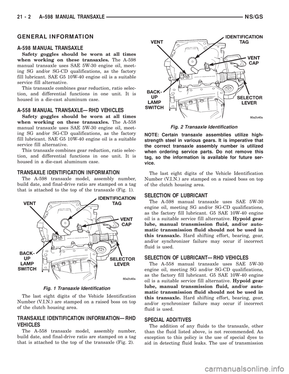
that is attached to the top of the transaxle (Fig. 1).
The last eight digits of the Vehicle Identification
Number (V.I.N.) are stamped on a raised boss on top
of the clutch housing area.
TRANSAXLE IDENTIFICATION INFORMATIONÐRHD
VEHICLES
The A-558 transaxle model, assembly number,
build date, and final-drive ratio are stamped on a tag
that is attached to the top of the transaxle (Fig. 2).NOTE: Certain transaxle assemblies utilize high-
strength steel in various gears. It is imperative that
the correct transaxle assembly number is utilized
when ordering service parts. Do not remove this
tag, so the information is available for future ser-
vice.
The last eight digits of the Vehicle Identification
Number (V.I.N.) are stamped on a raised boss on top
of the clutch housing area.
SELECTION OF LUBRICANT
The A-598 manual transaxle uses SAE 5W-30
engine oil, meeting SG and/or SG-CD qualifications,
as the factory fill lubricant. G5 SAE 10W-40 engine
oil is a suitable service fill alternative.Hypoid gear
lube, manual transmission fluid, and/or auto-
matic transmission fluid should not be used in
this transaxle.Hard shifting effort, bearing, gear,
and/or synchronizer failure may occur if incorrect
fluid is used.
SELECTION OF LUBRICANTÐRHD VEHICLES
The A-558 manual transaxle uses SAE 5W-30
engine oil, meeting SG and/or SG-CD qualifications,
as the factory fill lubricant. G5 SAE 10W-40 engine
oil is a suitable service fill alternative.Hypoid gear
lube, manual transmission fluid, and/or auto-
matic transmission fluid should not be used in
this transaxle.Hard shifting effort, bearing, gear,
and/or synchronizer failure may occur if incorrect
fluid is used.
SPECIAL ADDITIVES
The addition of any fluids to the transaxle, other
than the fluid listed above, is not recommended. An
exception to this policy is the use of special dyes to
aid in detecting fluid leaks. The use of transmission
Fig. 1 Transaxle Identification
Fig. 2 Transaxle Identification
21 - 2 A±598 MANUAL TRANSAXLENS/GS
Page 1659 of 1938
sealers should be avoided, since they may adversely
affect seals.
SPECIAL ADDITIVESÐRHD VEHICLES
The addition of any fluids to the transaxle, other
than the fluid listed above, is not recommended. An
exception to this policy is the use of special dyes to
aid in detecting fluid leaks. The use of transmission
sealers should be avoided, since they may adversely
affect seals.
GEAR RATIOS
Gear ratios for the 2.4L gasoline engine and 2.5L
Turbo Diesel MTX are as follows:
²1stÐ3.36
²2ndÐ1.90
²3rdÐ1.28
²4thÐ0.92
²5thÐ0.71
²ReverseÐ3.17
Final drive ratio of 3.88 was selected for maximum
performance. All forward gears are synchronized.
Gear ratios for the 2.0L GAS MTX are as follows:
²1stÐ3.69
²2ndÐ2.24
²3rdÐ1.45
²4thÐ1.03
²5thÐ0.81
²ReverseÐ3.17
Final drive ratio of 4.08 was selected for maximum
performance. All forward gears are synchronized.
GEAR RATIOSÐRHD VEHICLES
Gear ratios for the 2.0L GAS MTX are as follows:
²1stÐ3.69
²2ndÐ2.24
²3rdÐ1.45
²4thÐ0.1.03
²5thÐ0.81
²ReverseÐ3.17
Final drive ratio of 4.08 was selected for maximum
performance. All forward gears are synchronized.
GEARSHIFT PATTERN
The A-598 transaxle shift pattern is a H±pattern
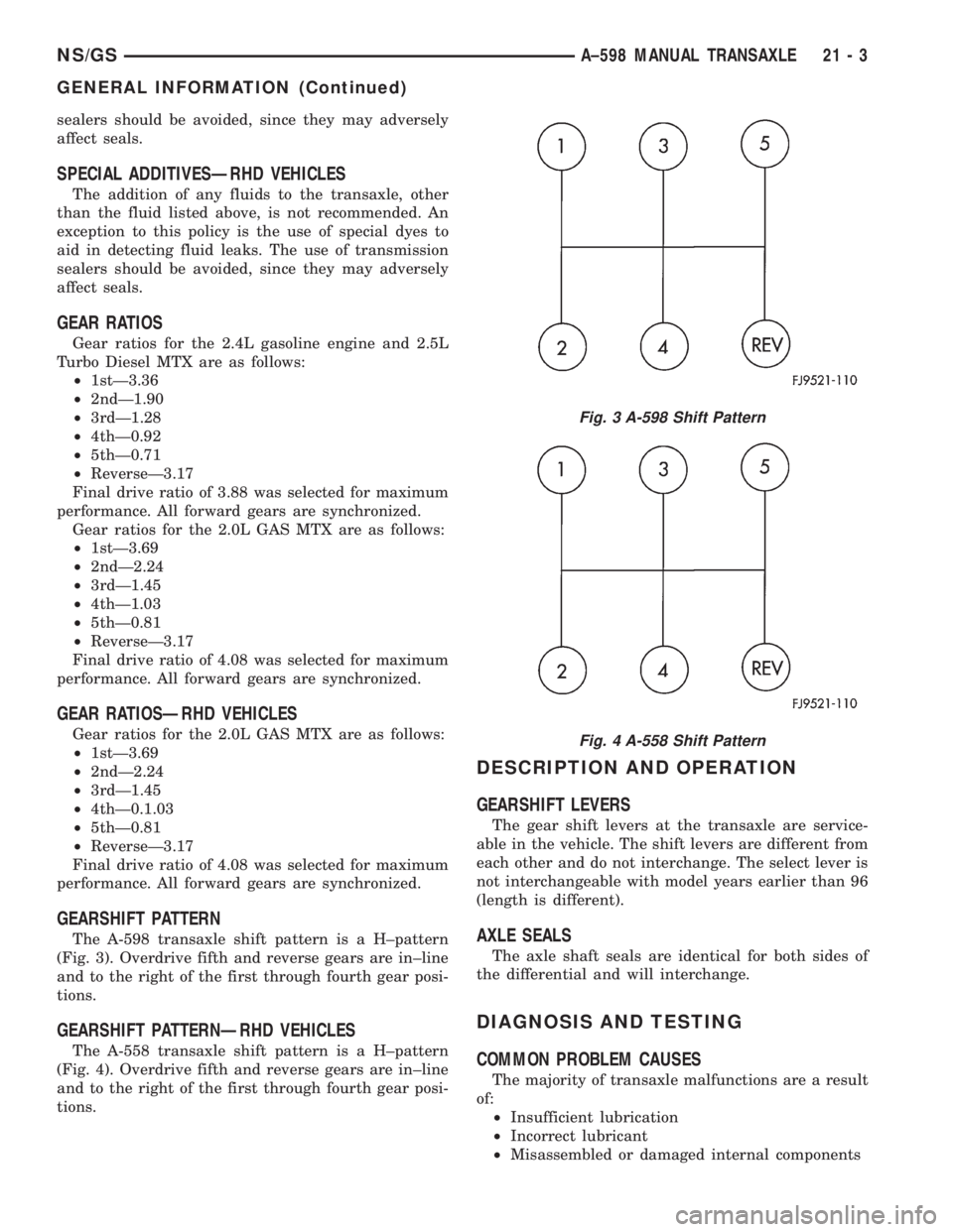
(Fig. 3). Overdrive fifth and reverse gears are in±line
and to the right of the first through fourth gear posi-
tions.
GEARSHIFT PATTERNÐRHD VEHICLES
The A-558 transaxle shift pattern is a H±pattern
(Fig. 4). Overdrive fifth and reverse gears are in±line
and to the right of the first through fourth gear posi-
tions.
DESCRIPTION AND OPERATION
GEARSHIFT LEVERS
The gear shift levers at the transaxle are service-
able in the vehicle. The shift levers are different from
each other and do not interchange. The select lever is
not interchangeable with model years earlier than 96
(length is different).
AXLE SEALS
The axle shaft seals are identical for both sides of
the differential and will interchange.
DIAGNOSIS AND TESTING
COMMON PROBLEM CAUSES
The majority of transaxle malfunctions are a result
of:
²Insufficient lubrication
²Incorrect lubricant
²Misassembled or damaged internal components
Fig. 3 A-598 Shift Pattern
Fig. 4 A-558 Shift Pattern
NS/GSA±598 MANUAL TRANSAXLE 21 - 3
GENERAL INFORMATION (Continued)