ECO mode CHRYSLER VOYAGER 1996 Repair Manual
[x] Cancel search | Manufacturer: CHRYSLER, Model Year: 1996, Model line: VOYAGER, Model: CHRYSLER VOYAGER 1996Pages: 1938, PDF Size: 55.84 MB
Page 1906 of 1938
cranking. Whenever the Powertrain Control Module
(PCM) sets a Diagnostic Trouble Code (DTC) that
affects vehicle emissions, it illuminates the MIL. If a
problem is detected, the PCM sends a message over
the CCD Bus to the instrument cluster to illuminate
the lamp. The PCM illuminates the MIL only for
DTC's that affect vehicle emissions. The MIL stays
on continuously when the PCM has entered a
Limp-In mode or identified a failed emission compo-
nent or system. The MIL remains on until the DTC
is erased. Refer to the Diagnostic Trouble Code
charts in this group for emission related codes.
Also, the MIL either flashes or illuminates contin-
uously when the PCM detects active engine misfire.
Refer to Misfire Monitoring in this section.
Additionally, the PCM may reset (turn off) the MIL
when one of the following occur:
²PCM does not detect the malfunction for 3 con-
secutive trips (except misfire and fuel system moni-
tors).
²PCM does not detect a malfunction while per-
forming three successive engine misfire or fuel sys-
tem tests. The PCM performs these tests while the
engine is operating within6375 RPM of and within
10 % of the load of the operating condition at which
the malfunction was first detected.
STATE DISPLAY TEST MODE
The switch inputs to the Powertrain Control Mod-
ule (PCM) have two recognized states; HIGH and
LOW. For this reason, the PCM cannot recognize the
difference between a selected switch position versus
an open circuit, a short circuit, or a defective switch.
If the State Display screen shows the change from
HIGH to LOW or LOW to HIGH, assume the entire
switch circuit to the PCM functions properly. From
the state display screen, access either State Display
Inputs and Outputs or State Display Sensors.
STATE DISPLAY INPUTS AND OUTPUTS
Connect the DRB scan tool to the data link connec-
tor and access the State Display screen. Then access
Inputs and Outputs. The following list contains the
PCM system functions accessible through the Inputs
and Outputs screen.
Park/Neutral Switch
Speed Control Resume
Brake Switch
Speed Control On/Off
Speed Control Set
S/C Vent Solenoid
Actual S/C Vent Sol.
S/C Vacuum Solenoid
Actual S/C Vacuum Sol.
S/C Cancel
S/C Last Cutout
S/C Working Status
S/C Denied Status
A/C Clutch Relay
Actual A/C Clutch Relay
EGR Solenoid
Actual EGR Sol.
Automatic Shutdown Relay
Actual Automatic Shutdown Relay
Automatic Shutdown Relay Sense
Radiator Fan Control Module
Actual Radiator Fan Control Module
Duty Cycle EVAP Purge Solenoid
Actual EVAP Purge Sol.
Torque Converter Clutch Solenoid
Power Steering Switch
Closed Loop State
Current CMP Edge
Current CKP State
Current Sync State
Fuel Pump Relay
Actual Fuel Pump Relay
Ignition Sense (A21)
Malfunction Lamp
Limp-in Reason
STATE DISPLAY SENSORS
Connect the DRB scan tool to the vehicle and
access the State Display screen. Then access Sensor
Display. The following list contains the PCM system
functions accessible through the Sensor Display
screen.
Battery Temperature
Engine Coolant Temperature
Engine Coolant Temp Sensor
Throttle Position Volts
Minimum Throttle
Knock Sensor Volts
Battery Voltage
MAP Sensor Reading
Idle Air Control Motor Position
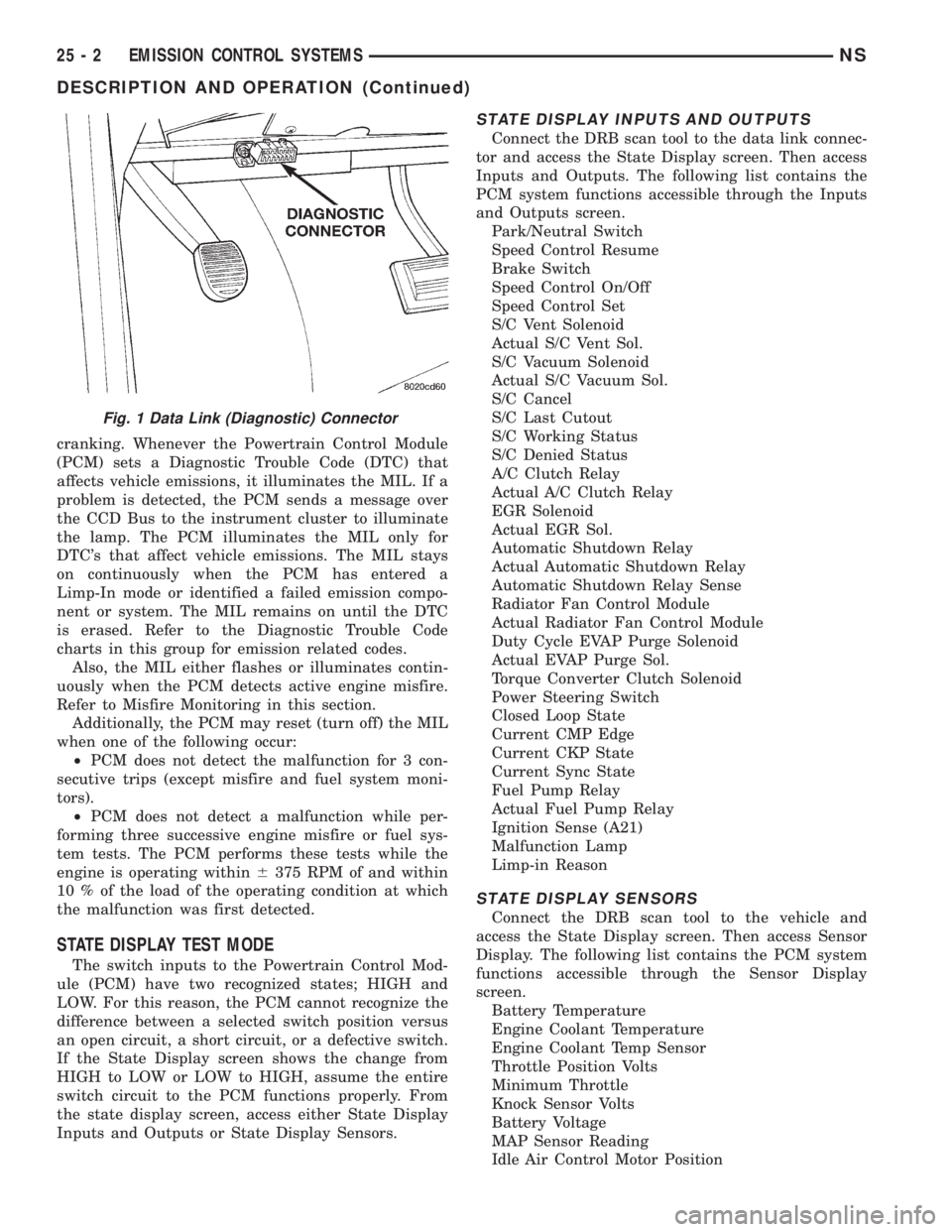
Fig. 1 Data Link (Diagnostic) Connector
25 - 2 EMISSION CONTROL SYSTEMSNS
DESCRIPTION AND OPERATION (Continued)
Page 1907 of 1938
Adaptive Fuel Factor
Barometric Pressure
Engine Speed
Module Spark Advance
Speed Control Target
Intake Air Temp Degrees
Intake Air Temp Volts
Charging System Goal
Theft Alarm Status
Map Sensor Voltage
Vehicle Speed
Throttle Opening (percentage)
TPS Calculated
Cam Timing Position
Target Idle
Time From Start To Run
Run Time At Stall
Injector Pulse-width
Upstream O2S Volts
Downstream O2S Volts
Closed Loop Timer
Short Term Adaptive
Current Adaptive Cell
Adaptive Memory Cell 0
Adaptive Memory Cell 1
Adaptive Memory Cell 2
Adaptive Memory Cell 3
Adaptive Memory Cell 4
Adaptive Memory Cell 5
Adaptive Memory Cell 6
Adaptive Memory Cell 7
Adaptive Memory Cell 8
Adaptive Memory Cell 9
Adaptive Memory Cell 10
Adaptive Memory Cell 11
Adaptive Memory Cell 12
Adaptive Memory Cell 13
Adaptive Memory Cell 14
Adaptive Memory Cell 15
Purge Free Idle Cell
Purge Free Cell 2 (corresponds to memory cell 2)
Purge Free Cell 3 (corresponds to memory cell 5)
Target IAC Steps
Retard Cylinder (1)
Retard Cylinder (2)
Retard Cylinder (3)
Retard Cylinder (4)
Retard Cylinder (5)
Retard Cylinder (6)CIRCUIT ACTUATION TEST MODE
The Circuit Actuation Test Mode checks for proper
operation of output circuits or devices the Powertrain
Control Module (PCM) may not internally recognize.
The PCM attempts to activate these outputs and
allow an observer to verify proper operation. Most of
the tests provide an audible or visual indication of
device operation (click of relay contacts, fuel spray,
etc.). Except for intermittent conditions, if a device
functions properly during testing, assume the device,
its associated wiring, and driver circuit work cor-
rectly.
DIAGNOSTIC TROUBLE CODES
A Diagnostic Trouble Code (DTC) indicates the
PCM has recognized an abnormal condition in the
system.
The preferred and most accurate method of retriev-
ing a DTC is by using the DRB scan tool. The scan
tool supplies detailed diagnostic information which
can be used to more accurately diagnose causes for a
DTC.
Remember that DTC's are the results of a sys-
tem or circuit failure, but do not directly iden-
tify the failed component or components.
NOTE: For a list of DTC's, refer to the charts in this
section.
BULB CHECK
Each time the ignition key is turned to the ON
position, the malfunction indicator (check engine)
lamp on the instrument panel should illuminate for
approximately 2 seconds then go out. This is done for
a bulb check.
OBTAINING DTC'S USING DRB SCAN TOOL
(1) Connect the DRB scan tool to the data link
(diagnostic) connector. This connector is located in
the passenger compartment; at the lower edge of
instrument panel; near the steering column.
(2) Turn the ignition switch on and access the
ªRead Faultº screen.
(3) Record all the DTC's and ªfreeze frameº infor-
mation shown on the DRB scan tool.
(4) To erase DTC's, use the ªErase Trouble Codeº
data screen on the DRB scan tool.Do not erase any
DTC's until problems have been investigated
and repairs have been performed.
NSEMISSION CONTROL SYSTEMS 25 - 3
DESCRIPTION AND OPERATION (Continued)
Page 1915 of 1938
components now have input (rationality) and output
(functionality) checks. Previously, a component like
the Throttle Position sensor (TPS) was checked by
the PCM for an open or shorted circuit. If one of
these conditions occurred, a DTC was set. Now there
is a check to ensure that the component is working.
This is done by watching for a TPS indication of a
greater or lesser throttle opening than MAP and
engine rpm indicate. In the case of the TPS, if engine
vacuum is high and engine rpm is 1600 or greater
and the TPS indicates a large throttle opening, a
DTC will be set. The same applies to low vacuum
and 1600 rpm.
Any component that has an associated limp in will
set a fault after 1 trip with the malfunction present.
Refer to the Diagnostic Trouble Codes Description
Charts in this section and the appropriate Power-
train Diagnostic Procedure Manual for diagnostic
procedures.
NON-MONITORED CIRCUITS
The PCM does not monitor all circuits, systems
and conditions that could have malfunctions causing
driveability problems. However, problems with these
systems may cause the PCM to store diagnostic trou-
ble codes for other systems or components. For exam-
ple, a fuel pressure problem will not register a fault
directly, but could cause a rich/lean condition or mis-
fire. This could cause the PCM to store an oxygen
sensor or misfire diagnostic trouble code.
The major non-monitored circuits are listed below
along with examples of failures modes that do not
directly cause the PCM to set a DTC, but for a sys-
tem that is monitored.
FUEL PRESSURE
The fuel pressure regulator controls fuel system
pressure. The PCM cannot detect a clogged fuel
pump inlet filter, clogged in-line fuel filter, or a
pinched fuel supply or return line. However, these
could result in a rich or lean condition causing the
PCM to store an oxygen sensor or fuel system diag-
nostic trouble code.
SECONDARY IGNITION CIRCUIT
The PCM cannot detect an inoperative ignition coil,
fouled or worn spark plugs, ignition cross firing, or
open spark plug cables.
CYLINDER COMPRESSION
The PCM cannot detect uneven, low, or high engine
cylinder compression.
EXHAUST SYSTEM
The PCM cannot detect a plugged, restricted or
leaking exhaust system. It may set a EGR or Fuel
system fault or O2S.
FUEL INJECTOR MECHANICAL
MALFUNCTIONS
The PCM cannot determine if a fuel injector is
clogged, the needle is sticking or if the wrong injector
is installed. However, these could result in a rich or
lean condition causing the PCM to store a diagnostic
trouble code for either misfire, an oxygen sensor, or
the fuel system.
EXCESSIVE OIL CONSUMPTION
Although the PCM monitors engine exhaust oxygen
content when the system is in closed loop, it cannot
determine excessive oil consumption.
THROTTLE BODY AIR FLOW
The PCM cannot detect a clogged or restricted air
cleaner inlet or filter element.
VACUUM ASSIST
The PCM cannot detect leaks or restrictions in the
vacuum circuits of vacuum assisted engine control
system devices. However, these could cause the PCM
to store a MAP sensor diagnostic trouble code and
cause a high idle condition.
PCM SYSTEM GROUND
The PCM cannot determine a poor system ground.
However, one or more diagnostic trouble codes may
be generated as a result of this condition. The mod-
ule should be mounted to the body at all times, also
during diagnostic.
PCM CONNECTOR ENGAGEMENT
The PCM may not be able to determine spread or
damaged connector pins. However, it might store
diagnostic trouble codes as a result of spread connec-
tor pins.
HIGH AND LOW LIMITS
The PCM compares input signal voltages from each
input device with established high and low limits for
the device. If the input voltage is not within limits
and other criteria are met, the PCM stores a diagnos-
tic trouble code in memory. Other diagnostic trouble
code criteria might include engine RPM limits or
input voltages from other sensors or switches that
must be present before verifying a diagnostic trouble
code condition.
NSEMISSION CONTROL SYSTEMS 25 - 11
DESCRIPTION AND OPERATION (Continued)
Page 1918 of 1938
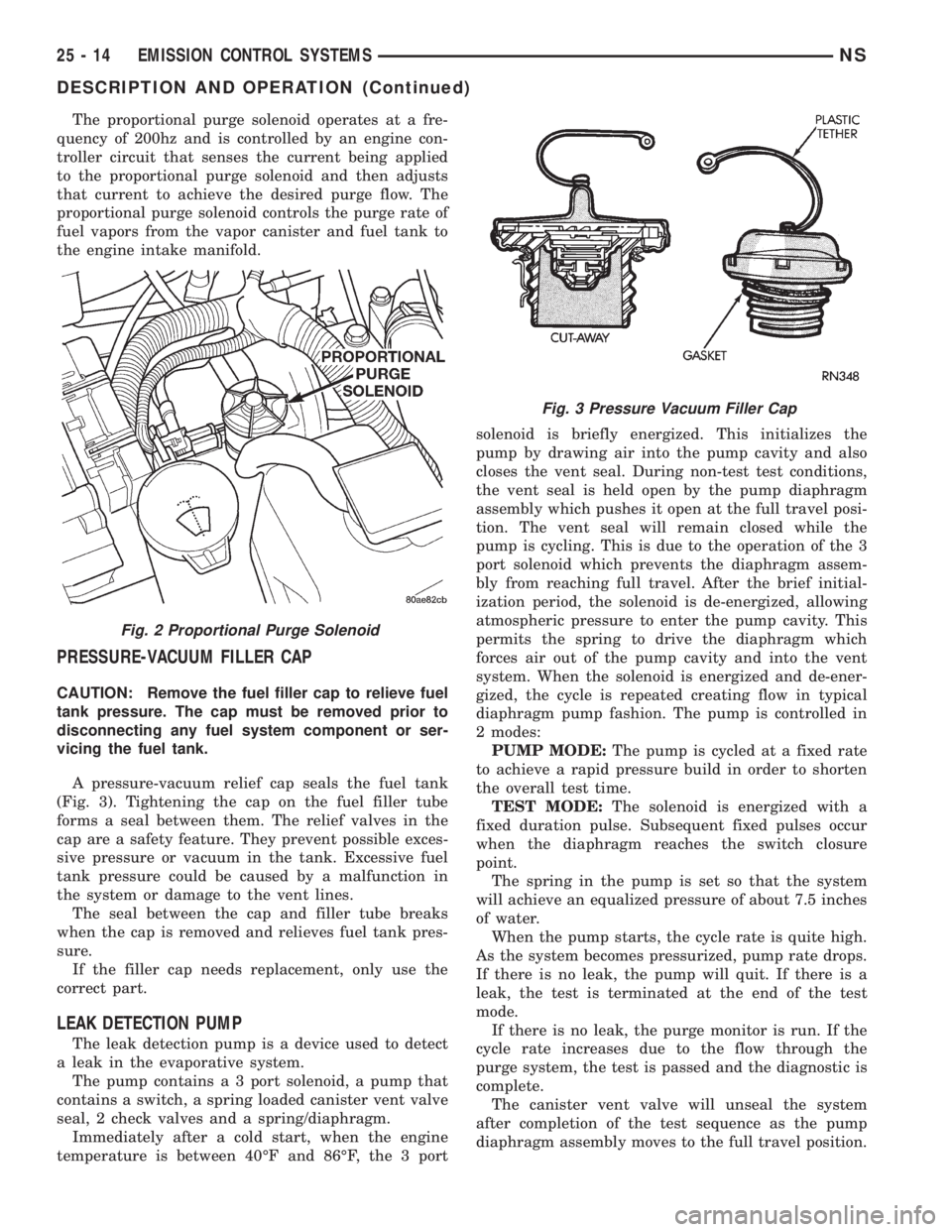
The proportional purge solenoid operates at a fre-
quency of 200hz and is controlled by an engine con-
troller circuit that senses the current being applied
to the proportional purge solenoid and then adjusts
that current to achieve the desired purge flow. The
proportional purge solenoid controls the purge rate of
fuel vapors from the vapor canister and fuel tank to
the engine intake manifold.
PRESSURE-VACUUM FILLER CAP
CAUTION: Remove the fuel filler cap to relieve fuel
tank pressure. The cap must be removed prior to
disconnecting any fuel system component or ser-
vicing the fuel tank.
A pressure-vacuum relief cap seals the fuel tank
(Fig. 3). Tightening the cap on the fuel filler tube
forms a seal between them. The relief valves in the
cap are a safety feature. They prevent possible exces-
sive pressure or vacuum in the tank. Excessive fuel
tank pressure could be caused by a malfunction in
the system or damage to the vent lines.
The seal between the cap and filler tube breaks
when the cap is removed and relieves fuel tank pres-
sure.
If the filler cap needs replacement, only use the
correct part.
LEAK DETECTION PUMP
The leak detection pump is a device used to detect
a leak in the evaporative system.
The pump contains a 3 port solenoid, a pump that
contains a switch, a spring loaded canister vent valve
seal, 2 check valves and a spring/diaphragm.
Immediately after a cold start, when the engine
temperature is between 40ÉF and 86ÉF, the 3 portsolenoid is briefly energized. This initializes the
pump by drawing air into the pump cavity and also
closes the vent seal. During non-test test conditions,
the vent seal is held open by the pump diaphragm
assembly which pushes it open at the full travel posi-
tion. The vent seal will remain closed while the
pump is cycling. This is due to the operation of the 3
port solenoid which prevents the diaphragm assem-
bly from reaching full travel. After the brief initial-
ization period, the solenoid is de-energized, allowing
atmospheric pressure to enter the pump cavity. This
permits the spring to drive the diaphragm which
forces air out of the pump cavity and into the vent
system. When the solenoid is energized and de-ener-
gized, the cycle is repeated creating flow in typical
diaphragm pump fashion. The pump is controlled in
2 modes:
PUMP MODE:The pump is cycled at a fixed rate
to achieve a rapid pressure build in order to shorten
the overall test time.
TEST MODE:The solenoid is energized with a
fixed duration pulse. Subsequent fixed pulses occur
when the diaphragm reaches the switch closure
point.
The spring in the pump is set so that the system
will achieve an equalized pressure of about 7.5 inches
of water.
When the pump starts, the cycle rate is quite high.
As the system becomes pressurized, pump rate drops.
If there is no leak, the pump will quit. If there is a
leak, the test is terminated at the end of the test
mode.
If there is no leak, the purge monitor is run. If the
cycle rate increases due to the flow through the
purge system, the test is passed and the diagnostic is
complete.
The canister vent valve will unseal the system
after completion of the test sequence as the pump
diaphragm assembly moves to the full travel position.
Fig. 2 Proportional Purge Solenoid
Fig. 3 Pressure Vacuum Filler Cap
25 - 14 EMISSION CONTROL SYSTEMSNS
DESCRIPTION AND OPERATION (Continued)
Page 1919 of 1938
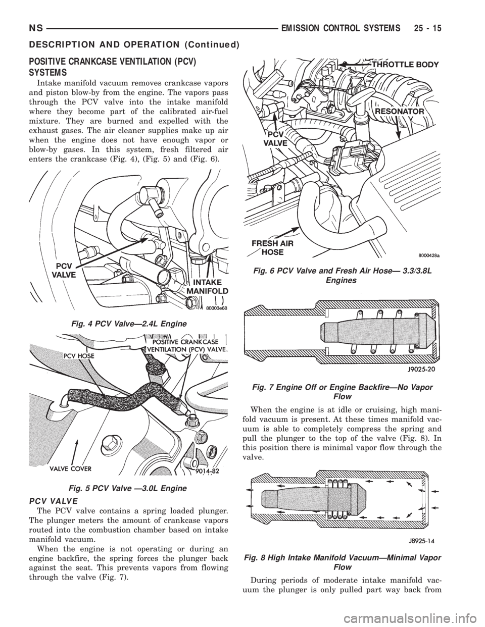
POSITIVE CRANKCASE VENTILATION (PCV)
SYSTEMS
Intake manifold vacuum removes crankcase vapors
and piston blow-by from the engine. The vapors pass
through the PCV valve into the intake manifold
where they become part of the calibrated air-fuel
mixture. They are burned and expelled with the
exhaust gases. The air cleaner supplies make up air
when the engine does not have enough vapor or
blow-by gases. In this system, fresh filtered air
enters the crankcase (Fig. 4), (Fig. 5) and (Fig. 6).
PCV VALVE
The PCV valve contains a spring loaded plunger.
The plunger meters the amount of crankcase vapors
routed into the combustion chamber based on intake
manifold vacuum.
When the engine is not operating or during an
engine backfire, the spring forces the plunger back
against the seat. This prevents vapors from flowing
through the valve (Fig. 7).When the engine is at idle or cruising, high mani-
fold vacuum is present. At these times manifold vac-
uum is able to completely compress the spring and
pull the plunger to the top of the valve (Fig. 8). In
this position there is minimal vapor flow through the
valve.
During periods of moderate intake manifold vac-
uum the plunger is only pulled part way back from
Fig. 4 PCV ValveÐ2.4L Engine
Fig. 5 PCV Valve Ð3.0L Engine
Fig. 6 PCV Valve and Fresh Air HoseÐ 3.3/3.8L
Engines
Fig. 7 Engine Off or Engine BackfireÐNo Vapor
Flow
Fig. 8 High Intake Manifold VacuumÐMinimal Vapor
Flow
NSEMISSION CONTROL SYSTEMS 25 - 15
DESCRIPTION AND OPERATION (Continued)