engine oil capacity CHRYSLER VOYAGER 1996 Service Manual
[x] Cancel search | Manufacturer: CHRYSLER, Model Year: 1996, Model line: VOYAGER, Model: CHRYSLER VOYAGER 1996Pages: 1938, PDF Size: 55.84 MB
Page 215 of 1938
COOLING SYSTEM
CONTENTS
page page
GENERAL INFORMATION
ACCESSORY DRIVE BELTS................ 1
AUTOMATIC TRANSMISSION OIL COOLERÐ
2.4L................................. 3
COOLANT RECOVERY SYSTEM (CRS)....... 3
COOLANT.............................. 3
COOLING SYSTEM....................... 2
ENGINE BLOCK HEATER.................. 5
ENGINE THERMOSTAT.................... 3
RADIATOR PRESSURE CAP................ 4
RADIATOR............................. 3
WATER PUMPS......................... 3
DESCRIPTION AND OPERATION
COOLANT PERFORMANCE................. 6
RADIATOR HOSES AND CLAMPS........... 6
WATER PIPESÐ3.0L ENGINE.............. 6
WATER PUMPÐ3.3/3.8L ENGINES.......... 7
WATER PUMPÐ2.4L ENGINE.............. 6
WATER PUMPÐ3.0L ENGINE.............. 6
DIAGNOSIS AND TESTING
ACCESSORY DRIVE BELT.................. 7
COOLING SYSTEM DIAGNOSIS............. 8
DEAERATION.......................... 16
ELECTRIC FAN MOTOR TEST.............. 14
LOW COOLANT LEVEL AERATION.......... 15
PRESSURE TESTING RADIATOR CAP....... 15
RADIATOR CAP TO FILLER NECK SEAL
PRESSURE RELIEF CHECK.............. 15
RADIATOR COOLANT FLOW TEST.......... 14
RADIATOR FAN CONTROL................ 14
TEMPERATURE GAUGE INDICATION........ 16
TESTING COOLING SYSTEM FOR LEAKS.... 14
SERVICE PROCEDURES
COOLANT LEVEL CHECKÐROUTINE........ 16
COOLANT LEVEL SERVICE................ 16COOLANTÐADDING ADDITIONAL.......... 16
COOLING SYSTEMÐDRAINING............ 16
COOLING SYSTEMÐREFILLING........... 16
REMOVAL AND INSTALLATION
ACCESSORY DRIVE BELTSÐ2.4L.......... 23
ACCESSORY DRIVE BELTSÐ3.0L.......... 24
ACCESSORY DRIVE BELTÐ3.3/3.8L........ 24
ENGINE BLOCK HEATER................. 23
FAN MODULE.......................... 22
RADIATOR DRAINCOCK.................. 21
RADIATOR............................ 21
THERMOSTATÐ2.4L ENGINE............. 19
THERMOSTATÐ3.0L ENGINE............. 20
THERMOSTATÐ3.3/3.8L ENGINES......... 20
WATER PUMP INLET TUBEÐ2.4L ENGINE . . . 17
WATER PUMPÐ3.3/3.8L ENGINES......... 19
WATER PUMPÐ2.4L ENGINE............ 17
WATER PUMPÐ3.0L ENGINE............. 18
CLEANING AND INSPECTION
ACCESSORY DRIVE BELT................. 25
CHEMICAL CLEANING................... 25
COOLING SYSTEM CLEANING............. 25
RADIATOR PRESSURE CAP............... 25
REVERSE FLUSHING THE ENGINE......... 25
REVERSE FLUSHING THE RADIATOR....... 25
WATER PUMP......................... 24
ADJUSTMENTS
BELT TENSION CHART................... 26
BELT TENSION GAUGE METHOD........... 26
PROPER BELT TENSION................. 25
SPECIFICATIONS
COOLING SYSTEM CAPACITY............. 26
TORQUE CHART........................ 26
SPECIAL TOOLS
COOLING............................. 26
GENERAL INFORMATION
ACCESSORY DRIVE BELTS
The accessory drive system utilizes two different
style of drive belts. The conventional V-belt and the
Poly-V belt are used to drive the generator, air con-
ditioning compressor, power steering pump and waterpump. Satisfactory performance of these belts
depends on belt condition and proper belt tension.
Belt tensioning should be performed with the aid of a
Burroughs gauge Special Tool C-4162. Because of
space limitations in the engine compartment, the use
of the gauge may be restricted. Raise the vehicle on a
hoist and then remove the splash shield to gain
access to the drive belts.
NSCOOLING SYSTEM 7 - 1
Page 218 of 1938
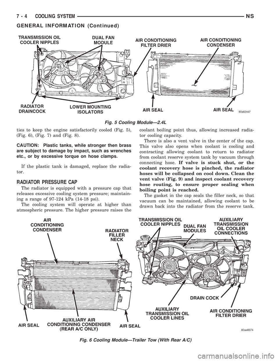
ties to keep the engine satisfactorily cooled (Fig. 5),
(Fig. 6), (Fig. 7) and (Fig. 8).
CAUTION: Plastic tanks, while stronger then brass
are subject to damage by impact, such as wrenches
etc., or by excessive torque on hose clamps.
If the plastic tank is damaged, replace the radia-
tor.
RADIATOR PRESSURE CAP
The radiator is equipped with a pressure cap that
releases excessive cooling system pressure; maintain-
ing a range of 97-124 kPa (14-18 psi).
The cooling system will operate at higher than
atmospheric pressure. The higher pressure raises thecoolant boiling point thus, allowing increased radia-
tor cooling capacity.
There is also a vent valve in the center of the cap.
This valve also opens when coolant is cooling and
contracting allowing coolant to return to radiator
from coolant reserve system tank by vacuum through
connecting hose.If valve is stuck shut, or the
coolant recovery hose is pinched, the radiator
hoses will be collapsed on cool down. Clean the
vent valve (Fig. 9) and inspect coolant recovery
hose routing, to ensure proper sealing when
boiling point is reached.
The gasket in the cap seals the filler neck, so that
vacuum can be maintained, allowing coolant to be
drawn back into the radiator from the reserve tank.
Fig. 5 Cooling ModuleÐ2.4L
Fig. 6 Cooling ModuleÐTrailer Tow (With Rear A/C)
7 - 4 COOLING SYSTEMNS
GENERAL INFORMATION (Continued)
Page 230 of 1938

at running operating temperature the high pressure
inlet tank runs full and the low pressure outlet tank
drops:
²Transmission oil will become hotter.
²High reading shown on the temperature gauge.
²Air in the coolant can cause loss of flow through
the heater.
²Exhaust gas leaks into the coolant also can
cause the same problems.
DEAERATION
Air can only be removed from the system by gath-
ering under the pressure cap. On the next heat up it
will be pushed past the pressure cap into the CRS
tank by thermal expansion of the coolant. It then
escapes to the atmosphere in the CRS tank and is
replaced with solid coolant on cool down.
TEMPERATURE GAUGE INDICATION
At idle with Air Conditioning off the temperature
gauge will rise slowly to about 5/8 gauge travel, the
fan will come on and the gauge will quickly drop to
about 1/2 gauge travel. This is normal.
SERVICE PROCEDURES
COOLANT LEVEL CHECKÐROUTINE
Do not remove radiator cap for routine cool-
ant level inspections.
The coolant reserve system provides a quick visual
method for determining the coolant level without
removing the radiator cap.With the engine cold
and not running,simply observe the level of the
coolant in the reserve tank (Fig. 3). The coolant level
should be between the minimum and maximum
marks.
COOLANTÐADDING ADDITIONAL
The radiator cap should not be removed.
When additional coolant is needed to maintain this
level, it should be added to the coolant reserve tank.
Use only 50/50 mix of ethylene glycol type antifreeze
and water.
CAUTION: Do not use well water, or suspect water
supply in cooling system. A 50/50 ethylene glycol
and distilled water mix is recommended.
COOLANT LEVEL SERVICE
The cooling system is closed and designed to main-
tain coolant level to the top of the radiator.
When servicing requires a coolant level check in
the radiator, the engine must beoffandnotunder
pressure. Drain several ounces of coolant from the
radiator draincock while observing the CoolantRecovery System (CRS) Tank. Coolant level in the
CRS tank should drop slightly. Then remove the radi-
ator cap. The radiator should be full to the top. If
not, and the coolant level in the CRS tank is at the
MIN mark there is an air leak in the CRS system.
Check hose or hose connections to the CRS tank,
radiator filler neck or the pressure cap seal to the
radiator filler neck for leaks.
COOLING SYSTEMÐDRAINING
Without removing radiator pressure cap and
with system not under pressure,shut engine off
and open draincock. The coolant reserve tank should
empty first, then remove radiator pressure cap. (if
not, see Testing Cooling System for leaks). To vent
2.4L engine remove the coolant temperature sensor
located above water outlet housing (Fig. 15). The 3.0/
3.3/3.8L engines have an air bleed vent on the ther-
mostat.
Removal of a sensor is required because the ther-
mostat does not have an air vent. Sensor removal
allows an air bleed for coolant to drain from the
engine block.
COOLING SYSTEMÐREFILLING
First clean system to remove old coolant, see Cool-
ing System Cleaning.
Fill the system, using the correct antifreeze as
described in the Coolant Section. Fill the system to
50 percent of its capacity with 100 percent glycol.
Then complete filling system with water. The 2.4L
engine requires venting by removal of the coolant
sensor on top of the water outlet connector (Fig. 15).
When coolant reaches this hole:
²Install coolant sensor and tighten to 7 N´m (60
in. lbs.) for 2.4L Engines.
Fig. 15 Coolant Temperature SensorÐ2.4L Engine
Drain/Fill
7 - 16 COOLING SYSTEMNS
DIAGNOSIS AND TESTING (Continued)
Page 240 of 1938
and the remove the splash shield to gain access to
the drive belts.
BELT TENSION GAUGE METHOD
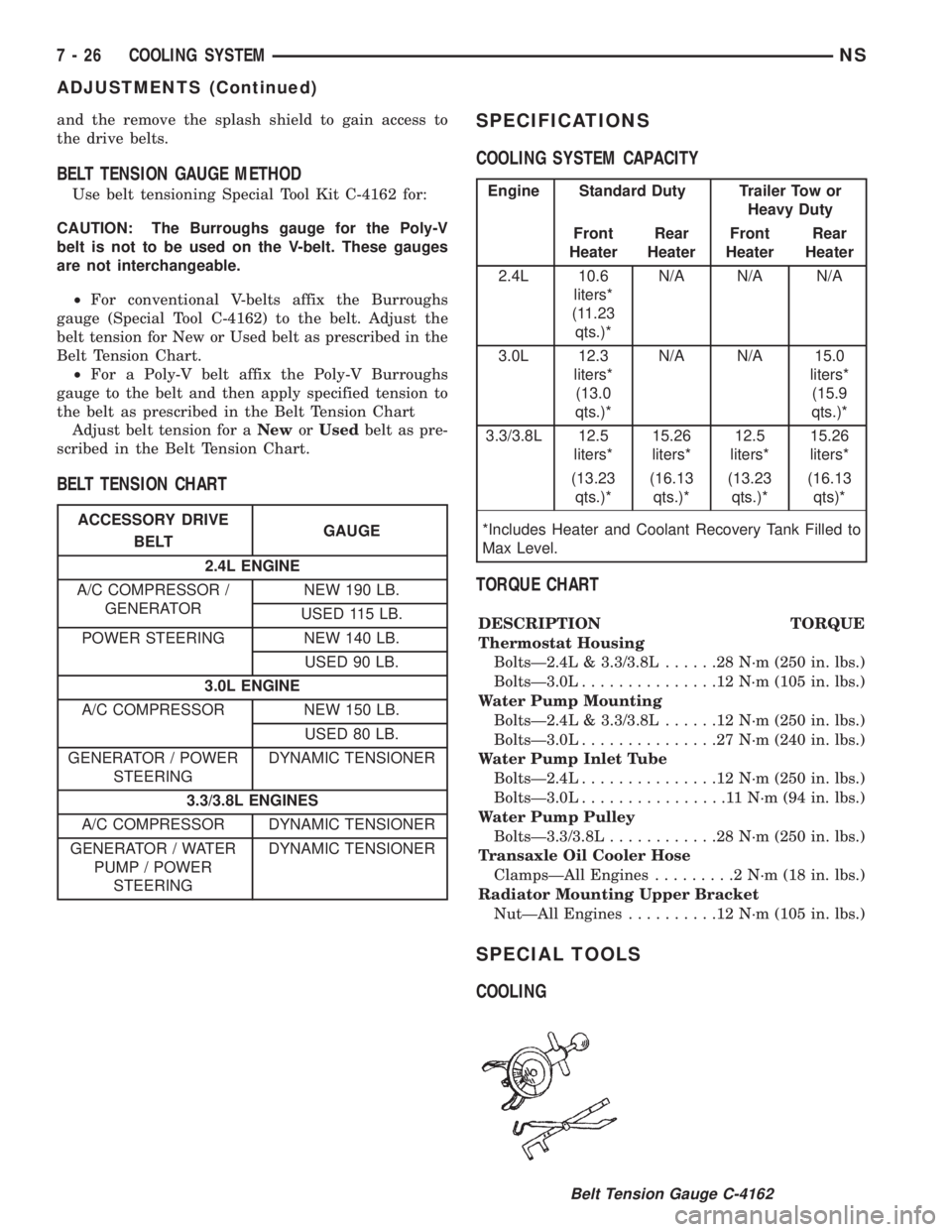
Use belt tensioning Special Tool Kit C-4162 for:
CAUTION: The Burroughs gauge for the Poly-V
belt is not to be used on the V-belt. These gauges
are not interchangeable.
²For conventional V-belts affix the Burroughs
gauge (Special Tool C-4162) to the belt. Adjust the
belt tension for New or Used belt as prescribed in the
Belt Tension Chart.
²For a Poly-V belt affix the Poly-V Burroughs
gauge to the belt and then apply specified tension to
the belt as prescribed in the Belt Tension Chart
Adjust belt tension for aNeworUsedbelt as pre-
scribed in the Belt Tension Chart.
BELT TENSION CHARTSPECIFICATIONS
COOLING SYSTEM CAPACITY
TORQUE CHART
DESCRIPTION TORQUE
Thermostat Housing
BoltsÐ2.4L & 3.3/3.8L......28N´m(250 in. lbs.)
BoltsÐ3.0L...............12N´m(105 in. lbs.)
Water Pump Mounting
BoltsÐ2.4L & 3.3/3.8L......12N´m(250 in. lbs.)
BoltsÐ3.0L...............27N´m(240 in. lbs.)
Water Pump Inlet Tube
BoltsÐ2.4L...............12N´m(250 in. lbs.)
BoltsÐ3.0L................11N´m(94in.lbs.)
Water Pump Pulley
BoltsÐ3.3/3.8L............28N´m(250 in. lbs.)
Transaxle Oil Cooler Hose
ClampsÐAll Engines.........2N´m(18in.lbs.)
Radiator Mounting Upper Bracket
NutÐAll Engines..........12N´m(105 in. lbs.)
SPECIAL TOOLS
COOLING
ACCESSORY DRIVE
BELTGAUGE
2.4L ENGINE
A/C COMPRESSOR /
GENERATORNEW 190 LB.
USED 115 LB.
POWER STEERING NEW 140 LB.
USED 90 LB.
3.0L ENGINE
A/C COMPRESSOR NEW 150 LB.
USED 80 LB.
GENERATOR / POWER
STEERINGDYNAMIC TENSIONER
3.3/3.8L ENGINES
A/C COMPRESSOR DYNAMIC TENSIONER
GENERATOR / WATER
PUMP / POWER
STEERINGDYNAMIC TENSIONER
Engine Standard Duty Trailer Tow or
Heavy Duty
Front
HeaterRear
HeaterFront
HeaterRear
Heater
2.4L 10.6
liters*
(11.23
qts.)*N/A N/A N/A
3.0L 12.3
liters*
(13.0
qts.)*N/A N/A 15.0
liters*
(15.9
qts.)*
3.3/3.8L 12.5
liters*15.26
liters*12.5
liters*15.26
liters*
(13.23
qts.)*(16.13
qts.)*(13.23
qts.)*(16.13
qts)*
*Includes Heater and Coolant Recovery Tank Filled to
Max Level.
Belt Tension Gauge C-4162
7 - 26 COOLING SYSTEMNS
ADJUSTMENTS (Continued)
Page 241 of 1938

COOLING SYSTEM
CONTENTS
page page
GENERAL INFORMATION
COOLANT PRESSURE BOTTLE............ 1
COOLING SYSTEM Ð 2.0L GASOLINE...... 1
COOLING SYSTEM Ð 2.5L VM DIESEL..... 1
LOW COOLANT LEVEL SENSOR........... 1
RADIATOR............................ 2
DESCRIPTION AND OPERATION
AUTOMATIC BELT TENSIONER............ 6
BELT TENSION......................... 5
COOLANT PERFORMANCE............... 5
PRESSURE/VENT CAP................... 4
THERMOSTAT OPERATION............... 4
THERMOSTAT......................... 6
WATER PUMP......................... 3
SERVICE PROCEDURES
ADDING ADDITIONAL COOLANT........... 7
DRAINING COOLING SYSTEM............. 7
REFILLING COOLING SYSTEM............ 7
REMOVAL AND INSTALLATION
ENGINE THERMOSTATÐ 2.0L GASOLINE . . . 9GENERATOR/POWER STEERING BELT Ð 2.5L
VM DIESEL......................... 10
RADIATOR Ð 2.5L VM DIESEL........... 9
THERMOSTAT Ð 2.5L VM DIESEL......... 9
WATER PUMP BELT Ð 2.5L VM DIESEL . . . 10
WATER PUMP Ð 2.0L GASOLINE......... 7
WATER PUMP Ð 2.5L VM DIESEL........ 8
CLEANING AND INSPECTION
WATER PUMP........................ 10
ADJUSTMENTS
BELT TENSION CHART................. 11
BELT TENSION GAUGE METHOD......... 11
SPECIFICATIONS
COOLING SYSTEM CAPACITY............ 12
TORQUE CHART...................... 12
SPECIAL TOOLS
COOLING............................ 12
GENERAL INFORMATION
COOLING SYSTEM Ð 2.0L GASOLINE
The 2.0L gasoline engine cooling system consists of
an engine cooling module, thermostat, coolant, a
water pump to circulate the coolant. The engine cool-
ing module may consist of a radiator, electric fan
motors, fan, shroud, coolant reserve system, hoses,
clamps, air condition condenser.
²When the Engine is cold: The thermostat is
closed; the cooling system has no flow through the
radiator. The coolant flows through the engine,
heater system and bypass.
²When the Engine is warm: Thermostat is open;
the cooling system has flow through radiator, engine,
heater system and bypass.
COOLING SYSTEM Ð 2.5L VM DIESEL
The cooling system has a radiator, coolant, electric
fan motors, shroud, pressure cap, thermostat, coolant
pressure bottle, hoses, a water pump to circulate the
coolant, to complete the circuit. Coolant flow for the
VM diesel engine is shown in (Fig. 1).
COOLANT PRESSURE BOTTLE
2.5L VM DIESEL
This system works with the pressure cap to use
thermal expansion and contraction of the coolant to
keep the coolant free of trapped air. It provides some
reserve coolant to cover minor leaks and evaporation
or boiling losses. The coolant pressure bottle location
for 2.5L diesel is above the cylinder head cover (Fig.
2).
LOW COOLANT LEVEL SENSOR
The low coolant level sensor checks for low coolant
level in the coolant tank. A signal will be sent from
this sensor to the Body Control Module (BCM). When
the BCM determines low coolant level for 30 contin-
uous seconds, the instrument panel mounted low
coolant level warning lamp will be illuminated. The
sensor is located on the front side of the coolant tank
(Fig. 4). For information, refer to Group 8E, Instru-
ment Panel and Gauges.
If this lamp is illuminated, it indicates the need to
fill the coolant tank and check for leaks.
NS/GSCOOLING SYSTEM 7 - 1
Page 244 of 1938
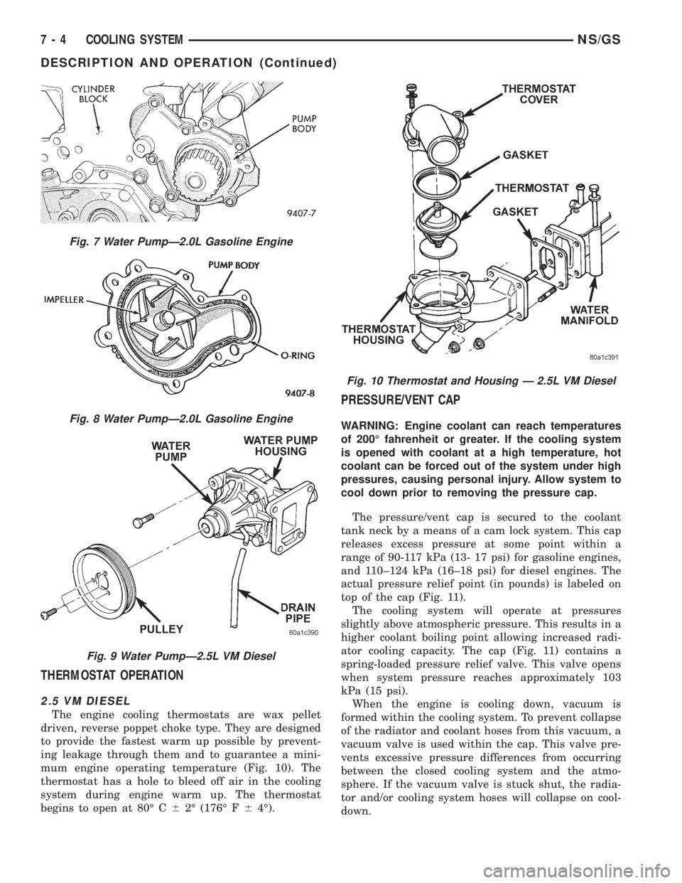
THERMOSTAT OPERATION
2.5 VM DIESEL
The engine cooling thermostats are wax pellet
driven, reverse poppet choke type. They are designed
to provide the fastest warm up possible by prevent-
ing leakage through them and to guarantee a mini-
mum engine operating temperature (Fig. 10). The
thermostat has a hole to bleed off air in the cooling
system during engine warm up. The thermostat
begins to open at 80É C62É (176É F64É).
PRESSURE/VENT CAP
WARNING: Engine coolant can reach temperatures
of 200É fahrenheit or greater. If the cooling system
is opened with coolant at a high temperature, hot
coolant can be forced out of the system under high
pressures, causing personal injury. Allow system to
cool down prior to removing the pressure cap.
The pressure/vent cap is secured to the coolant
tank neck by a means of a cam lock system. This cap
releases excess pressure at some point within a
range of 90-117 kPa (13- 17 psi) for gasoline engines,
and 110±124 kPa (16±18 psi) for diesel engines. The
actual pressure relief point (in pounds) is labeled on
top of the cap (Fig. 11).
The cooling system will operate at pressures
slightly above atmospheric pressure. This results in a
higher coolant boiling point allowing increased radi-
ator cooling capacity. The cap (Fig. 11) contains a
spring-loaded pressure relief valve. This valve opens
when system pressure reaches approximately 103
kPa (15 psi).
When the engine is cooling down, vacuum is
formed within the cooling system. To prevent collapse
of the radiator and coolant hoses from this vacuum, a
vacuum valve is used within the cap. This valve pre-
vents excessive pressure differences from occurring
between the closed cooling system and the atmo-
sphere. If the vacuum valve is stuck shut, the radia-
tor and/or cooling system hoses will collapse on cool-
down.
Fig. 7 Water PumpÐ2.0L Gasoline Engine
Fig. 8 Water PumpÐ2.0L Gasoline Engine
Fig. 9 Water PumpÐ2.5L VM Diesel
Fig. 10 Thermostat and Housing Ð 2.5L VM Diesel
7 - 4 COOLING SYSTEMNS/GS
DESCRIPTION AND OPERATION (Continued)
Page 1180 of 1938
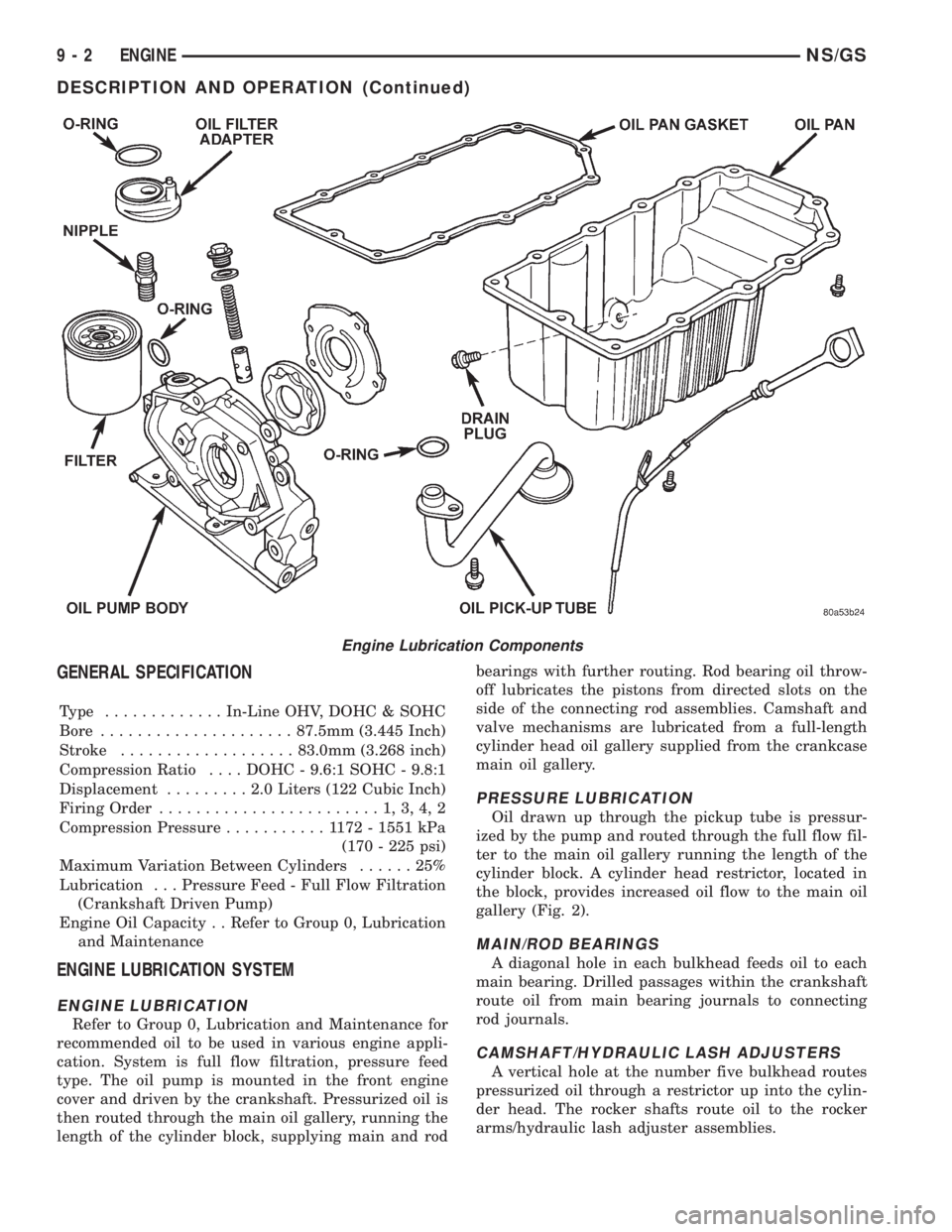
GENERAL SPECIFICATION
Type .............In-Line OHV, DOHC & SOHC
Bore.....................87.5mm (3.445 Inch)
Stroke...................83.0mm (3.268 inch)
Compression Ratio....DOHC - 9.6:1 SOHC - 9.8:1
Displacement.........2.0Liters (122 Cubic Inch)
Firing Order........................1,3,4,2
Compression Pressure...........1172-1551 kPa
(170 - 225 psi)
Maximum Variation Between Cylinders......25%
Lubrication . . . Pressure Feed - Full Flow Filtration
(Crankshaft Driven Pump)
Engine Oil Capacity . . Refer to Group 0, Lubrication
and Maintenance
ENGINE LUBRICATION SYSTEM
ENGINE LUBRICATION
Refer to Group 0, Lubrication and Maintenance for
recommended oil to be used in various engine appli-
cation. System is full flow filtration, pressure feed
type. The oil pump is mounted in the front engine
cover and driven by the crankshaft. Pressurized oil is
then routed through the main oil gallery, running the
length of the cylinder block, supplying main and rodbearings with further routing. Rod bearing oil throw-
off lubricates the pistons from directed slots on the
side of the connecting rod assemblies. Camshaft and
valve mechanisms are lubricated from a full-length
cylinder head oil gallery supplied from the crankcase
main oil gallery.
PRESSURE LUBRICATION
Oil drawn up through the pickup tube is pressur-
ized by the pump and routed through the full flow fil-
ter to the main oil gallery running the length of the
cylinder block. A cylinder head restrictor, located in
the block, provides increased oil flow to the main oil
gallery (Fig. 2).
MAIN/ROD BEARINGS
A diagonal hole in each bulkhead feeds oil to each
main bearing. Drilled passages within the crankshaft
route oil from main bearing journals to connecting
rod journals.
CAMSHAFT/HYDRAULIC LASH ADJUSTERS
A vertical hole at the number five bulkhead routes
pressurized oil through a restrictor up into the cylin-
der head. The rocker shafts route oil to the rocker
arms/hydraulic lash adjuster assemblies.
Engine Lubrication Components
9 - 2 ENGINENS/GS
DESCRIPTION AND OPERATION (Continued)
Page 1218 of 1938
2.5L VM DIESEL
INDEX
page page
GENERAL INFORMATION
ENGINE IDENTIFICATION................ 41
GENERAL SPECIFICATION............... 40
DESCRIPTION AND OPERATION
LUBRICATION SYSTEM.................. 41
DIAGNOSIS AND TESTING
ENGINE DIAGNOSISÐMECHANICAL....... 44
ENGINE DIAGNOSISÐPERFORMANCE..... 43
HYDRAULIC TAPPETS................... 47
SERVICE PROCEDURES
CHANGING ENGINE OIL AND FILTER....... 47
CHECKING OIL LEVEL................... 47
CRANKSHAFT END PLAY................ 50
FITTING PISTON RING.................. 50
TIMING PROCEDURE................... 49
VALVE AND SEAT REFACING............. 49
REMOVAL AND INSTALLATION
CAMSHAFT........................... 62
CAMSHAFT BEARINGS.................. 63
CRANKSHAFT MAIN BEARINGS........... 63
CRANKSHAFTÐREMOVAL............... 72
CYLINDER HEAD....................... 55
CYLINDER HEAD COVER................ 54
CYLINDER LINER...................... 72
ENGINE ASSEMBLY..................... 53
ENGINE MOUNTÐFRONT................ 51
ENGINE MOUNTÐREAR................. 52
ENGINE MOUNTÐRIGHT................ 51
HYDRAULIC TAPPETS................... 60
INJECTION PUMP...................... 61
MOUNTÐLEFT SIDE.................... 51
OIL FILTER ADAPTER AND OIL COOLER.... 68
OILPAN .............................. 66OIL PUMP............................ 67
OIL PUMP PRESSURE RELIEF VALVE...... 67
PISTONS AND CONNECTING ROD......... 68
REAR CRANKSHAFT OIL SEAL............ 72
ROCKER ARMS AND PUSH RODS......... 54
TIMING GEAR COVER................... 61
TIMING GEAR COVER OIL SEAL........... 61
VACUUM PUMP........................ 68
VALVE SPRINGSÐCYLINDER HEAD NOT
REMOVED.......................... 55
VALVES AND VALVE SPRINGSÐHEAD OFF . . 60
VIBRATION DAMPER.................... 61
DISASSEMBLY AND ASSEMBLY
HYDRAULIC TAPPETS................... 73
CLEANING AND INSPECTION
CRANKSHAFT......................... 77
CRANKSHAFT MAIN BEARING............ 77
CYLINDER HEAD....................... 75
CYLINDER HEAD COVERS............... 74
CYLINDER LINER...................... 78
HYDRAULIC TAPPETS................... 76
OILPAN .............................. 78
OIL PUMP............................ 76
PISTON AND CONNECTING ROD.......... 76
ROCKER ARMS AND PUSH RODS......... 74
TIMING GEAR COVER................... 75
VALVES AND VALVE SPRINGS............ 76
SPECIFICATIONS
2.5L VM DIESEL........................ 78
TORQUE............................. 80
SPECIAL TOOLS
2.5L VM DIESEL........................ 81
GENERAL INFORMATION
GENERAL SPECIFICATION
Type ........................425CLIEE (36B)
Displacement...................2.5L (2499 cc)
Bore.............................92.00 mm
Stroke............................94.00 mm
Compression Ratio....................20.95:1
Vacuum at Idle..........600mm/Hg (23.6 In/Hg)
Thermostat Opening................80ÉC62ÉC
Generator Rating............Bosch 50/120 Amp
Cooling System Capacity..............9.5Liter
Power Steering Capacity.............0.75 LiterType ........................425CLIEE (36B)
Engine Oil Capacity.....6.5Liters With Oil Filter
Change
Timing System . Pushrod Operated Overhead valves,
With Gear-Driven Camshaft.
Air Intake........................DryFilter
Fuel Feed...........Vacuum Pump Incorporated
in Injection Pump.
Fuel System.............Indirect Fuel Injection
(Precombustion Chamber)
Combustion Cycle....................4Stroke
Cooling System..................Water Cooled
Injection Pump.......Rotary Pump Electronically
Controlled.
9 - 40 ENGINENS/GS
Page 1256 of 1938
(3) If internal diameter of original bearing is being
checked and figures are not within specifications,
new bearings must be used.
(4) Check crankshaft main bearing journals to
bearing clearances. Clearances of main bearings is
.03 to .088mm (.0011 to .0035 in.).
OIL PAN
Remove all gasket material from cylinder block. Be
careful not gouge pan sealing surface.
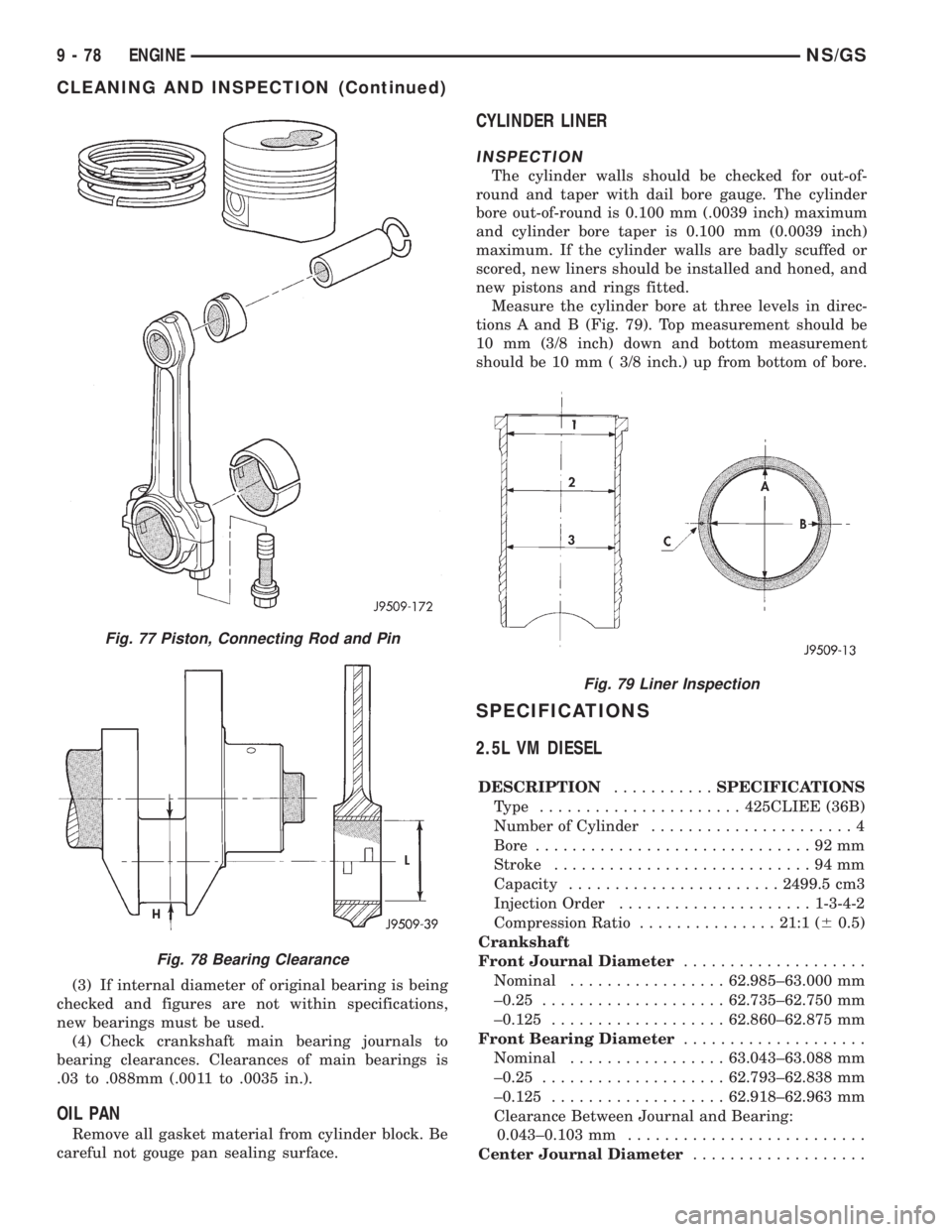
CYLINDER LINER
INSPECTION
The cylinder walls should be checked for out-of-
round and taper with dail bore gauge. The cylinder
bore out-of-round is 0.100 mm (.0039 inch) maximum
and cylinder bore taper is 0.100 mm (0.0039 inch)
maximum. If the cylinder walls are badly scuffed or
scored, new liners should be installed and honed, and
new pistons and rings fitted.
Measure the cylinder bore at three levels in direc-
tions A and B (Fig. 79). Top measurement should be
10 mm (3/8 inch) down and bottom measurement
should be 10 mm ( 3/8 inch.) up from bottom of bore.
SPECIFICATIONS
2.5L VM DIESEL
DESCRIPTION...........SPECIFICATIONS
Type ......................425CLIEE (36B)
Number of Cylinder......................4
Bore..............................92mm
Stroke............................94mm
Capacity.......................2499.5 cm3
Injection Order.....................1-3-4-2
Compression Ratio...............21:1 (60.5)
Crankshaft
Front Journal Diameter....................
Nominal.................62.985±63.000 mm
±0.25....................62.735±62.750 mm
±0.125...................62.860±62.875 mm
Front Bearing Diameter....................
Nominal.................63.043±63.088 mm
±0.25....................62.793±62.838 mm
±0.125...................62.918±62.963 mm
Clearance Between Journal and Bearing:
0.043±0.103 mm..........................
Center Journal Diameter...................
Fig. 77 Piston, Connecting Rod and Pin
Fig. 78 Bearing Clearance
Fig. 79 Liner Inspection
9 - 78 ENGINENS/GS
CLEANING AND INSPECTION (Continued)
Page 1547 of 1938
CAUTION: Some clutch packs appear similar, but
they are not the same. Do not interchange clutch
components, as they might fail.
HYDRAULICS
The hydraulics of the transaxle provide:
²Manual shift lever select function
²Main line pressure regulation
²Torque converter and cooler flow control
Oil flow to the friction elements is controlled
directly by four solenoid valves. The hydraulics also
include a unique logic- controlled solenoid torque con-
verter clutch control valve. This valve locks out the
1st gear reaction element with the application of 2nd,
direct, or overdrive gear elements. It also redirects
the 1st gear solenoid output so that it can control
torque converter clutch operation. To regain access to
1st gear, a sequence of commands must be used to
move the solenoid TCC control valve. This precludes
any application of the 1st gear reaction element with
other elements applied. It also allows one solenoid to
control two friction elements.
Small, high-rate accumulators are provided in each
controlled friction element circuit. These serve to
absorb the pressure responses, and allow the controls
to read and respond to changes that are occurring.
SOLENOIDS
The solenoid valves perform most control functions,
these valves must be extremely durable and tolerant
of dirt. For that reason hardened-steel poppet and
ball valves are used. These are free from any close
operating clearances. The solenoids operate the
valves directly without any intermediate element.
Direct operation means that these units must have
very high output. They must close against the size-
able flow areas and high line pressures. Fast
response is also required to meet the control require-
ments.
Two of the solenoids are normally-venting and two
are normally-applying; this was done to provide a
default mode of operation. With no electrical power,
the transmission provides 2nd gear in (OD), (3), or
(L) shift lever positions. All other transmission lever
positions will operate normally. The choice of 2nd
gear was made to provide adequate breakaway per-
formance while still accommodating highway speeds.
SENSORS
There are three pressure switches to identify sole-
noid application. There are two speed sensors to read
input (torque converter turbine) and output (parking
sprag) speeds. There is also a transmission range
sensor to indicate the manual shift lever position.
The pressure switches are incorporated in an assem-
bly with the solenoids. Engine speed, throttle posi-tion, temperature, etc., are also observed. Some of
these signals are read directly from the engine con-
trol sensors; others are read from a multiplex circuit
with the powertrain control module.
ELECTRONICS
The 41TE Transmission Control Module (TCM) is
located underhood in a potted, die-cast aluminum
housing. The module used is a new controller called
EATX III. The TCM has a sealed, 60-way connector.
ADAPTIVE CONTROLS
These controls function by reading the input and
output speeds over 140 times a second and respond-
ing to each new reading. This provides the precise
and sophisticated friction element control needed to
make smooth clutch-to-clutch shifts for all gear
changes. The use of overrunning clutches or other
shift quality aids are not required. As with most
automatic transaxles, all shifts involve releasing one
element and applying a different element. In simpli-
fied terms, the upshift logic allows the releasing ele-
ment to slip backwards slightly. This ensures that it
does not have excess capacity. The apply element is
filled until it begins to make the speed change to the
higher gear. The apply pressure is then controlled to
maintain the desired rate of speed change. This con-
tinues until the shift is made. The key to providing
excellent shift quality is precision. For example, the
release element for upshifts is allowed to slip back-
wards slightly. The amount of that slip is typically
less than a total of 20 degrees. To achieve that pre-
cision, the TCM learns the traits of the transaxle
that it is controlling. It learns the release rate of the
releasing element and the apply time of the applying
element. It also learns the rate at which the apply
element builds pressure sufficient to begin making
the speed change. This method achieves more preci-
sion than would be possible with exacting tolerances.
It can also adapt to any changes that occur with age
or environment.
For kickdown shifts, the control logic allows the
releasing element to slip. Then controls the rate at
which the input (and engine) accelerate. When the
lower gear speed is achieved, the releasing element
reapplies to maintain that speed until the apply ele-
ment is filled. This provides quick response since the
engine begins to accelerate immediately. This also
provides a smooth torque exchange since the release
element can control the rate of torque increase. This
control can make any powertrain feel more respon-
sive without increasing harshness.
Adaptive controls respond to input speed changes.
They compensate for changes in engine or friction
element torque and provide good, consistent shift
quality for the life of the transaxle.
NSTRANSAXLE AND POWER TRANSFER UNIT 21 - 73
DESCRIPTION AND OPERATION (Continued)