boot CHRYSLER VOYAGER 1996 User Guide
[x] Cancel search | Manufacturer: CHRYSLER, Model Year: 1996, Model line: VOYAGER, Model: CHRYSLER VOYAGER 1996Pages: 1938, PDF Size: 55.84 MB
Page 64 of 1938
²Inspect jounce bumper for cracks and signs of
deterioration.
(13) Replace any components of the strut assembly
found to be worn or defective during the inspection,
before re-assembling the strut.
ASSEMBLY
(1) Clamp strut in vise, with strut in vertical posi-
tion.Do not clamp strut in vise by body of strut,
only by the clevis bracket (Fig. 68).
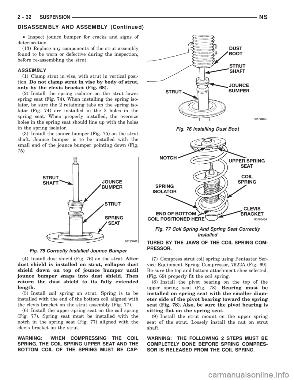
(2) Install the spring isolator on the strut lower
spring seat (Fig. 74). When installing the spring iso-
lator, be sure the 2 retaining tabs on the spring iso-
lator (Fig. 74) are installed in the 2 holes in the
spring seat. When properly installed, the oversize
holes in the spring seat should line up with the holes
in the spring isolator.
(3) Install the jounce bumper (Fig. 75) on the strut
shaft. Jounce bumper is to be installed with the
small end of the jounce bumper pointing down (Fig.
75).
(4) Install dust shield (Fig. 76) on the strut.After
dust shield is installed on strut, collapse dust
shield down on top of jounce bumper until
jounce bumper snaps into dust shield. Then
return the dust shield to its fully extended
length.
(5) Install coil spring on strut. Spring is to be
installed with the end of the bottom coil aligned with
the clevis bracket on the strut assembly (Fig. 77).
(6) Install the upper spring seat on the coil spring
(Fig. 77). Spring seat must be installed with the
notch in the spring seat (Fig. 77) aligned with the
clevis bracket on the strut.
WARNING: WHEN COMPRESSING THE COIL
SPRING, THE COIL SPRING UPPER SEAT AND THE
BOTTOM COIL OF THE SPRING MUST BE CAP-TURED BY THE JAWS OF THE COIL SPRING COM-
PRESSOR.
(7) Compress strut coil spring using Pentastar Ser-
vice Equipment Spring Compressor, 7522A (Fig. 69).
Be sure the top and bottom attachment shoe selected,
(Fig. 69) properly fit the coil spring.
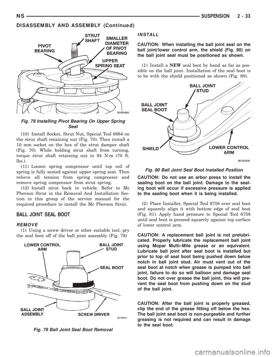
(8) Install the pivot bearing on the top of the
upper spring seat (Fig. 78).Bearing must be
installed on spring seat with the smaller diam-
eter side of the pivot bearing toward the spring
seat (Fig. 78). Also, be sure the pivot bearing is
sitting flat on the spring seat.
(9) Install the strut mount on the upper spring
seat of the strut. Loosely install the nut on strut
shaft.
WARNING: THE FOLLOWING 2 STEPS MUST BE
COMPLETELY DONE BEFORE SPRING COMPRES-
SOR IS RELEASED FROM THE COIL SPRING.
Fig. 75 Correctly Installed Jounce Bumper
Fig. 76 Installing Dust Boot
Fig. 77 Coil Spring And Spring Seat Correctly
Installed
2 - 32 SUSPENSIONNS
DISASSEMBLY AND ASSEMBLY (Continued)
Page 65 of 1938
(10) Install Socket, Strut Nut, Special Tool 6864 on
the strut shaft retaining nut (Fig. 70). Then install a
10 mm socket on the hex of the strut damper shaft
(Fig. 70). While holding strut shaft from turning,
torque strut shaft retaining nut to 94 N´m (70 ft.
lbs.).
(11) Loosen spring compressor until top coil of
spring is fully seated against upper spring seat. Then
relieve all tension from spring compressor and
remove spring compressor from strut spring.
(12) Install strut back in vehicle. Refer to Mc
Pherson Strut in the Removal And Installation Sec-
tion in this group of the service manual for the
required procedure to install the Mc Pherson Strut.
BALL JOINT SEAL BOOT
REMOVE
(1) Using a screw driver or other suitable tool, pry
the seal boot off of the ball joint assembly (Fig. 79)
INSTALL
CAUTION: When installing the ball joint seal on the
ball joint/lower control arm, the shield (Fig. 80) on
the ball joint seal must be positioned as shown.
(1) Install aNEWseal boot by hand as far as pos-
sible on the ball joint. Installation of the seal boot is
to be with the shield positioned as shown (Fig. 80).
CAUTION: Do not use an arbor press to install the
sealing boot on the ball joint. Damage to the seal-
ing boot will occur if excessive pressure is applied
to the sealing boot when it is being installed.
(2) Place Installer, Special Tool 6758 over seal boot
and squarely align it with bottom edge of seal boot
(Fig. 81). Apply hand pressure to Special Tool 6758
until seal boot is pressed squarely against top surface
of lower control arm.
CAUTION: A replacement ball joint is not prelubri-
cated. Properly lubricate the replacement ball joint
using Mopar Multi±Mile grease or an equivalent.
Lubricate ball joint after seal boot is installed but
prior to top of seal boot being pushed down below
notch in ball joint stud. Air must vent out of the
seal boot at notch when grease is pumped into ball
joint, failure to do so will balloon and damage seal
boot. Do not over grease the ball joint, this will pre-
vent the seal boot from pushing down on the stud
of the ball joint.
CAUTION: After the ball joint is properly greased,
clip the end of the grease fitting off below the hex.
The ball joint seal boot is non-purgeable and further
greasing is not required and can result in damage
to the seal boot.
Fig. 78 Installing Pivot Bearing On Upper Spring
Seat
Fig. 79 Ball Joint Seal Boot Removal
Fig. 80 Ball Joint Seal Boot Installed Position
NSSUSPENSION 2 - 33
DISASSEMBLY AND ASSEMBLY (Continued)
Page 66 of 1938
LOWER CONTROL ARM FRONT BUSHING
REMOVE
(1) Remove the lower control arm from the front
suspension cradle. Refer to Lower Control Arm in the
Removal And Installation Section in this section of
the service manual for the required procedure.
(2) Securely mount the lower control arm in a vise.
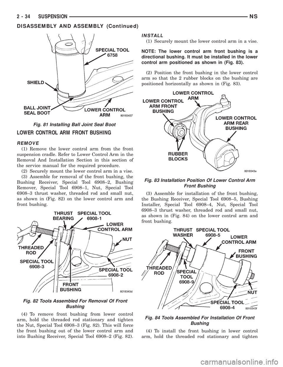
(3) Assemble for removal of the front bushing, the
Bushing Receiver, Special Tool 6908±2, Bushing
Remover, Special Tool 6908±1, Nut, Special Tool
6908±3 thrust washer, threaded rod and small nut,
as shown in (Fig. 82) on the lower control arm and
front bushing.
(4) To remove front bushing from lower control
arm, hold the threaded rod stationary and tighten
the Nut, Special Tool 6908±3 (Fig. 82). This will force
the front bushing out of the lower control arm and
into Bushing Receiver, Special Tool 6908±2 (Fig. 82).
INSTALL
(1) Securely mount the lower control arm in a vise.
NOTE: The lower control arm front bushing is a
directional bushing. It must be installed in the lower
control arm positioned as shown in (Fig. 83).
(2) Position the front bushing in the lower control
arm so that the 2 rubber blocks on the bushing are
positioned horizontally as shown in (Fig. 83).
(3) Assemble for installation of the front bushing,
the Bushing Receiver, Special Tool 6908±5, Bushing
Installer, Special Tool 6908±4, Nut, Special Tool
6908±3 thrust washer, threaded rod and small nut,
as shown in (Fig. 84) on the lower control arm and
front bushing.
(4) To install the front bushing in lower control
arm, hold the threaded rod stationary and tighten
Fig. 81 Installing Ball Joint Seal Boot
Fig. 82 Tools Assembled For Removal Of Front
Bushing
Fig. 83 Installation Position Of Lower Control Arm
Front Bushing
Fig. 84 Tools Assembled For Installation Of Front
Bushing
2 - 34 SUSPENSIONNS
DISASSEMBLY AND ASSEMBLY (Continued)
Page 87 of 1938
The caliper is a one piece casting with the inboard
side containing a single piston cylinder bore.
The phenolic piston is 60 mm (2.36 inch) in diam-
eter.
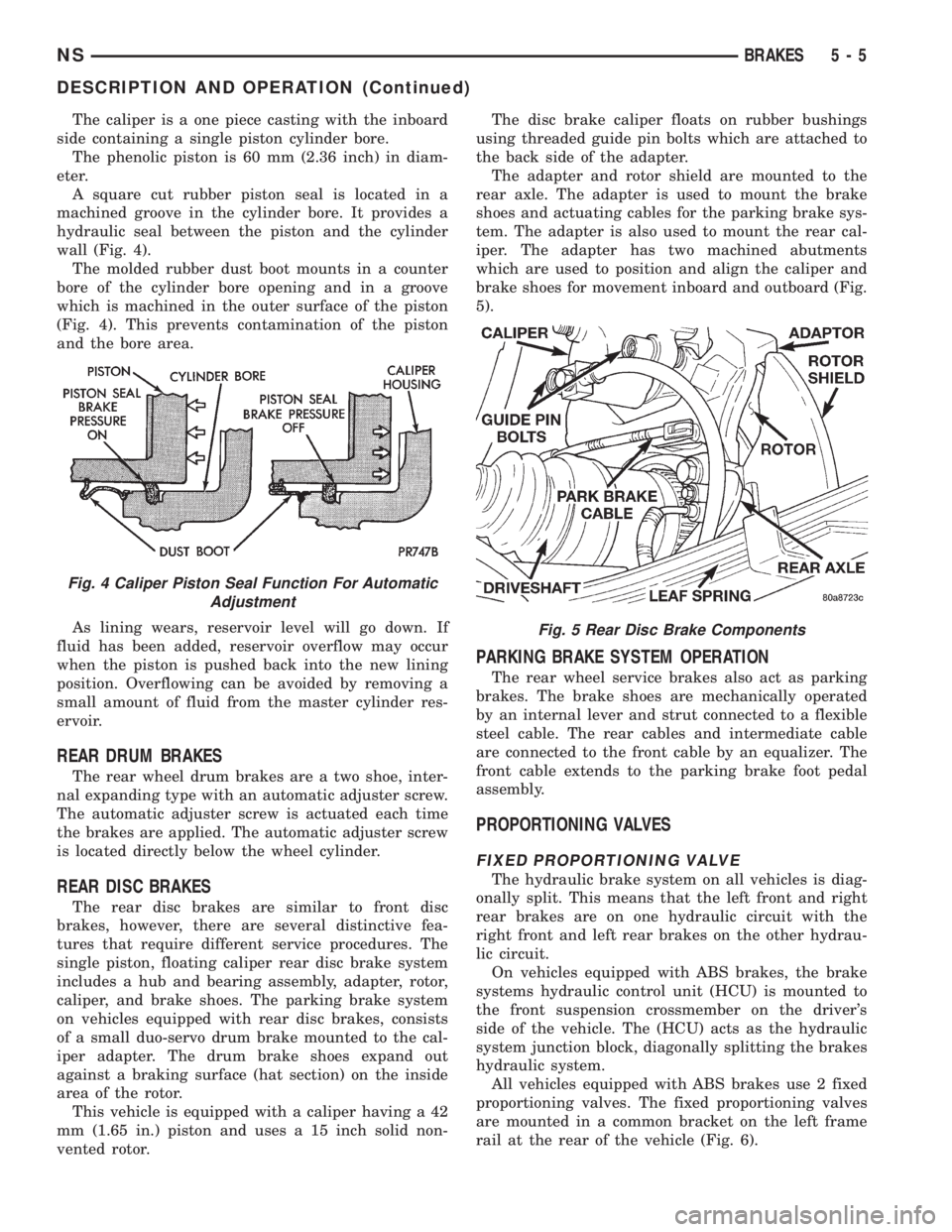
A square cut rubber piston seal is located in a
machined groove in the cylinder bore. It provides a
hydraulic seal between the piston and the cylinder
wall (Fig. 4).
The molded rubber dust boot mounts in a counter
bore of the cylinder bore opening and in a groove
which is machined in the outer surface of the piston
(Fig. 4). This prevents contamination of the piston
and the bore area.
As lining wears, reservoir level will go down. If
fluid has been added, reservoir overflow may occur
when the piston is pushed back into the new lining
position. Overflowing can be avoided by removing a
small amount of fluid from the master cylinder res-
ervoir.
REAR DRUM BRAKES
The rear wheel drum brakes are a two shoe, inter-
nal expanding type with an automatic adjuster screw.
The automatic adjuster screw is actuated each time
the brakes are applied. The automatic adjuster screw
is located directly below the wheel cylinder.
REAR DISC BRAKES
The rear disc brakes are similar to front disc
brakes, however, there are several distinctive fea-
tures that require different service procedures. The
single piston, floating caliper rear disc brake system
includes a hub and bearing assembly, adapter, rotor,
caliper, and brake shoes. The parking brake system
on vehicles equipped with rear disc brakes, consists
of a small duo-servo drum brake mounted to the cal-
iper adapter. The drum brake shoes expand out
against a braking surface (hat section) on the inside
area of the rotor.
This vehicle is equipped with a caliper having a 42
mm (1.65 in.) piston and uses a 15 inch solid non-
vented rotor.The disc brake caliper floats on rubber bushings
using threaded guide pin bolts which are attached to
the back side of the adapter.
The adapter and rotor shield are mounted to the
rear axle. The adapter is used to mount the brake
shoes and actuating cables for the parking brake sys-
tem. The adapter is also used to mount the rear cal-
iper. The adapter has two machined abutments
which are used to position and align the caliper and
brake shoes for movement inboard and outboard (Fig.
5).
PARKING BRAKE SYSTEM OPERATION
The rear wheel service brakes also act as parking
brakes. The brake shoes are mechanically operated
by an internal lever and strut connected to a flexible
steel cable. The rear cables and intermediate cable
are connected to the front cable by an equalizer. The
front cable extends to the parking brake foot pedal
assembly.
PROPORTIONING VALVES
FIXED PROPORTIONING VALVE
The hydraulic brake system on all vehicles is diag-
onally split. This means that the left front and right
rear brakes are on one hydraulic circuit with the
right front and left rear brakes on the other hydrau-
lic circuit.
On vehicles equipped with ABS brakes, the brake
systems hydraulic control unit (HCU) is mounted to
the front suspension crossmember on the driver's
side of the vehicle. The (HCU) acts as the hydraulic
system junction block, diagonally splitting the brakes
hydraulic system.
All vehicles equipped with ABS brakes use 2 fixed
proportioning valves. The fixed proportioning valves
are mounted in a common bracket on the left frame
rail at the rear of the vehicle (Fig. 6).
Fig. 4 Caliper Piston Seal Function For Automatic
Adjustment
Fig. 5 Rear Disc Brake Components
NSBRAKES 5 - 5
DESCRIPTION AND OPERATION (Continued)
Page 104 of 1938
MASTER CYLINDER BLEEDING PROCEDURE
CAUTION: When clamping master cylinder in vise,
only clamp master cylinder by its mounting flange,
do not clamp on primary piston, seal\boot or body
of master cylinder.
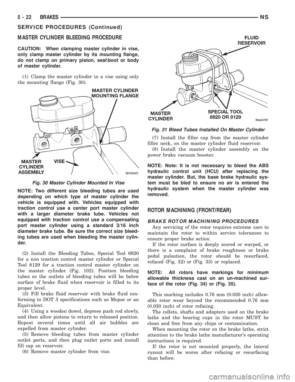
(1) Clamp the master cylinder in a vise using only
the mounting flange (Fig. 30).
NOTE: Two different size bleeding tubes are used
depending on which type of master cylinder the
vehicle is equipped with. Vehicles equipped with
traction control use a center port master cylinder
with a larger diameter brake tube. Vehicles not
equipped with traction control use a compensating
port master cylinder using a standard 3/16 inch
diameter brake tube. Be sure the correct size bleed-
ing tubes are used when bleeding the master cylin-
der.
(2) Install the Bleeding Tubes, Special Tool 6920
for a non traction control master cylinder or Special
Tool 8129 for a traction control master cylinder on
the master cylinder (Fig. 102). Position bleeding
tubes so the outlets of bleeding tubes will be below
surface of brake fluid when reservoir is filled to its
proper level.
(3) Fill brake fluid reservoir with brake fluid con-
forming to DOT 3 specifications such as Mopar or an
Equivalent.
(4) Using a wooden dowel, depress push rod slowly,
and then allow pistons to return to released position.
Repeat several times until all air bubbles are
expelled from master cylinder.
(5) Remove bleeding tubes from master cylinder
outlet ports, and then plug outlet ports and install
fill cap on reservoir.
(6) Remove master cylinder from vise.(7) Install the filler cap from the master cylinder
filler neck, on the master cylinder fluid reservoir.
(8) Install the master cylinder assembly on the
power brake vacuum booster.
NOTE: Note: It is not necessary to bleed the ABS
hydraulic control unit (HCU) after replacing the
master cylinder. But, the base brake hydraulic sys-
tem must be bled to ensure no air is entered the
hydraulic system when the master cylinder was
removed.
ROTOR MACHINING (FRONT/REAR)
BRAKE ROTOR MACHINING PROCEDURES
Any servicing of the rotor requires extreme care to
maintain the rotor to within service tolerances to
ensure proper brake action.
If the rotor surface is deeply scored or warped, or
there is a complaint of brake roughness or brake
pedal pulsation, the rotor should be resurfaced,
refaced (Fig. 32) or (Fig. 33) or replaced.
NOTE: All rotors have markings for minimum
allowable thickness cast on an un-machined sur-
face of the rotor (Fig. 34) or (Fig. 35).
This marking includes 0.76 mm (0.030 inch) allow-
able rotor wear beyond the recommended 0.76 mm
(0.030 inch) of rotor refacing.
The collets, shafts and adapters used on the brake
lathe and the bearing cups in the rotor MUST be
clean and free from any chips or contamination.
When mounting the rotor on the brake lathe, strict
attention to the brake lathe manufacturer's operating
instructions is required.
If the rotor is not mounted properly, the lateral
runout will be worse after refacing or resurfacing
than before.
Fig. 30 Master Cylinder Mounted In Vise
Fig. 31 Bleed Tubes Installed On Master Cylinder
5 - 22 BRAKESNS
SERVICE PROCEDURES (Continued)
Page 114 of 1938
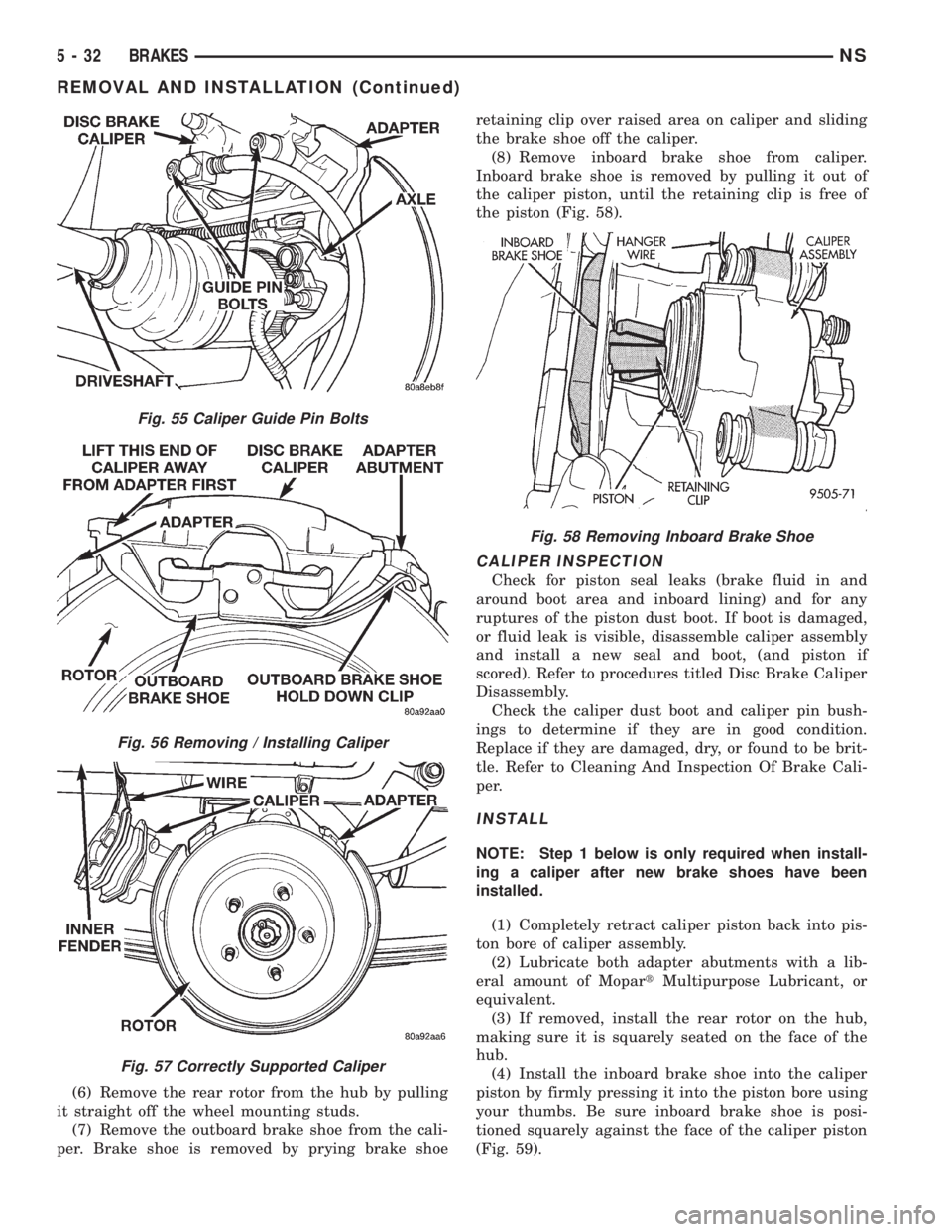
(6) Remove the rear rotor from the hub by pulling
it straight off the wheel mounting studs.
(7) Remove the outboard brake shoe from the cali-
per. Brake shoe is removed by prying brake shoeretaining clip over raised area on caliper and sliding
the brake shoe off the caliper.
(8) Remove inboard brake shoe from caliper.
Inboard brake shoe is removed by pulling it out of
the caliper piston, until the retaining clip is free of
the piston (Fig. 58).
CALIPER INSPECTION
Check for piston seal leaks (brake fluid in and
around boot area and inboard lining) and for any
ruptures of the piston dust boot. If boot is damaged,
or fluid leak is visible, disassemble caliper assembly
and install a new seal and boot, (and piston if
scored). Refer to procedures titled Disc Brake Caliper
Disassembly.
Check the caliper dust boot and caliper pin bush-
ings to determine if they are in good condition.
Replace if they are damaged, dry, or found to be brit-
tle. Refer to Cleaning And Inspection Of Brake Cali-
per.
INSTALL
NOTE: Step 1 below is only required when install-
ing a caliper after new brake shoes have been
installed.
(1) Completely retract caliper piston back into pis-
ton bore of caliper assembly.
(2) Lubricate both adapter abutments with a lib-
eral amount of MopartMultipurpose Lubricant, or
equivalent.
(3) If removed, install the rear rotor on the hub,
making sure it is squarely seated on the face of the
hub.
(4) Install the inboard brake shoe into the caliper
piston by firmly pressing it into the piston bore using
your thumbs. Be sure inboard brake shoe is posi-
tioned squarely against the face of the caliper piston
(Fig. 59).
Fig. 55 Caliper Guide Pin Bolts
Fig. 56 Removing / Installing Caliper
Fig. 57 Correctly Supported Caliper
Fig. 58 Removing Inboard Brake Shoe
5 - 32 BRAKESNS
REMOVAL AND INSTALLATION (Continued)
Page 127 of 1938

CAUTION: Before removing the master cylinder
from the power brake vacuum booster, the master
cylinder and vacuum booster must be thoroughlycleaned. This must be done to prevent dirt particles
from falling into the power brake vacuum booster.
(6) Clean the area where the master cylinder
assembly attaches to the power brake booster. Use
only a solvent such as Mopar Brake Parts Cleaner or
an equivalent.
(7) Remove the 2 nuts attaching the master cylin-
der assembly to the brake vacuum booster (Fig. 100).
(8) Slide master cylinder assembly straight out of
the power brake vacuum booster.
CAUTION: The master cylinder is used to create
the seal for holding vacuum in the power brake vac-
uum booster. The vacuum seal/boot on the master
cylinder MUST be replaced whenever the master
cylinder is removed from the power brake vacuum
booster.
(9) Remove the vacuum seal located on the mount-
ing flange of the master cylinder. The vacuum seal is
removed from the master cylinder bycarefullypull-
ing it away from the master cylinder.Do not
attempt to pry the seal off the master cylinder
by inserting a sharp tool between seal and mas-
ter cylinder casting.
BLEEDING MASTER CYLINDER
CAUTION: When clamping master cylinder in vise,
only clamp master cylinder by its mounting flange,
do not clamp on primary piston, seal or body of
master cylinder.
(1) Clamp the master cylinder in a vise using only
the mounting flange (Fig. 101).
Fig. 97 Master Cylinder Filler Tube Removal
Fig. 98 Electrical Connector At Fluid Level Sensor
Fig. 99 Primary/Secondary Brake Tubes At Master
Cylinder
Fig. 100 Master Cylinder Mounting To Vacuum
Booster
NSBRAKES 5 - 45
REMOVAL AND INSTALLATION (Continued)
Page 153 of 1938
MASTER CYLINDER FLUID RESERVOIR FILL TUBE
The master cylinder fluid reservoir filler neck is
removable from the master cylinder fluid reservoir.
The filler neck if required, can be replaced as a sep-
arate component of the fluid reservoir.
The filler neck is removed and installed using the
following procedure.
REMOVE
(1) Check brake fluid level in master cylinder fluid
reservoir to be sure brake fluid is not in the filler
neck. If brake fluid is in filler neck, lower fluid level
before removing filler neck from fluid reservoir
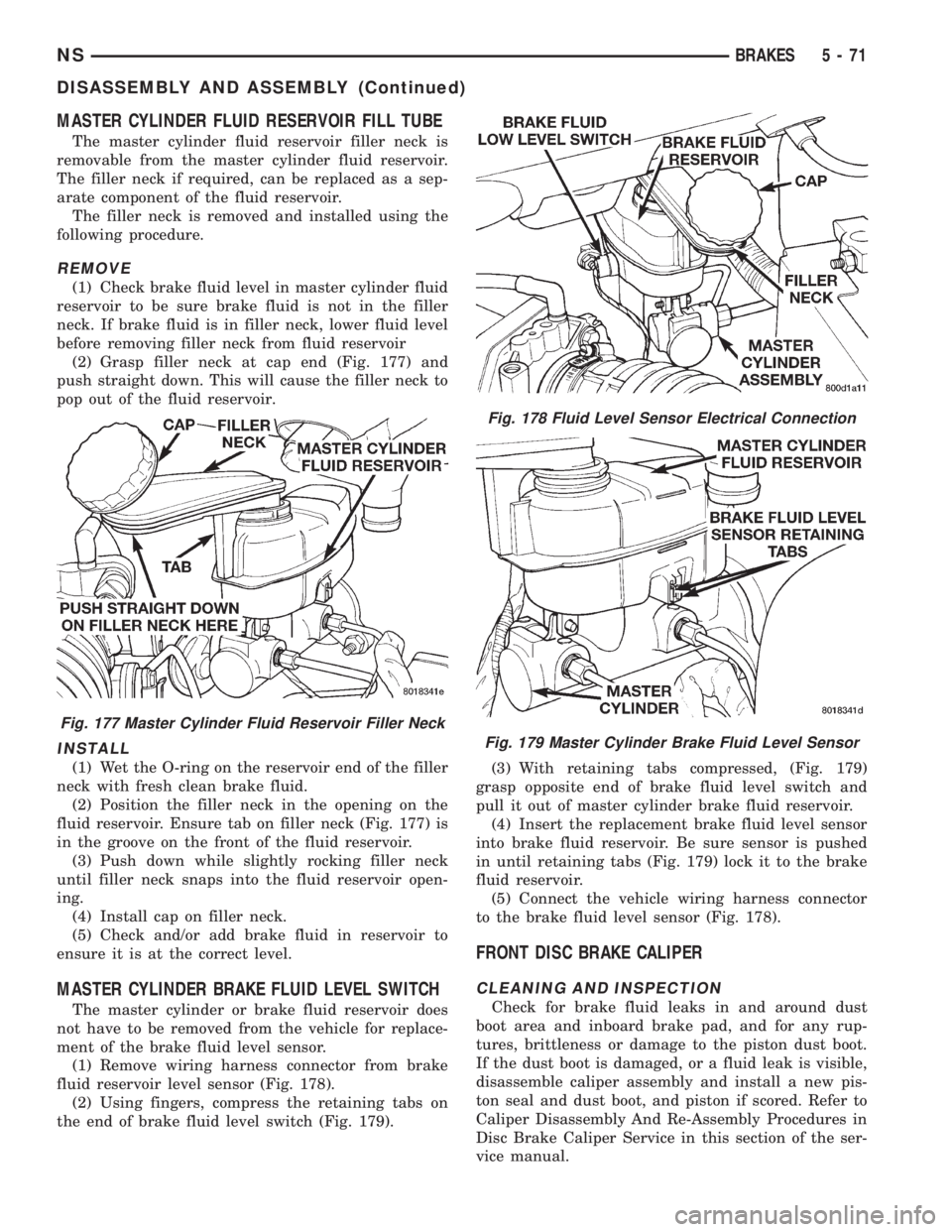
(2) Grasp filler neck at cap end (Fig. 177) and
push straight down. This will cause the filler neck to
pop out of the fluid reservoir.
INSTALL
(1) Wet the O-ring on the reservoir end of the filler
neck with fresh clean brake fluid.
(2) Position the filler neck in the opening on the
fluid reservoir. Ensure tab on filler neck (Fig. 177) is
in the groove on the front of the fluid reservoir.
(3) Push down while slightly rocking filler neck
until filler neck snaps into the fluid reservoir open-
ing.
(4) Install cap on filler neck.
(5) Check and/or add brake fluid in reservoir to
ensure it is at the correct level.
MASTER CYLINDER BRAKE FLUID LEVEL SWITCH
The master cylinder or brake fluid reservoir does
not have to be removed from the vehicle for replace-
ment of the brake fluid level sensor.
(1) Remove wiring harness connector from brake
fluid reservoir level sensor (Fig. 178).
(2) Using fingers, compress the retaining tabs on
the end of brake fluid level switch (Fig. 179).(3) With retaining tabs compressed, (Fig. 179)
grasp opposite end of brake fluid level switch and
pull it out of master cylinder brake fluid reservoir.
(4) Insert the replacement brake fluid level sensor
into brake fluid reservoir. Be sure sensor is pushed
in until retaining tabs (Fig. 179) lock it to the brake
fluid reservoir.
(5) Connect the vehicle wiring harness connector
to the brake fluid level sensor (Fig. 178).
FRONT DISC BRAKE CALIPER
CLEANING AND INSPECTION
Check for brake fluid leaks in and around dust
boot area and inboard brake pad, and for any rup-
tures, brittleness or damage to the piston dust boot.
If the dust boot is damaged, or a fluid leak is visible,
disassemble caliper assembly and install a new pis-
ton seal and dust boot, and piston if scored. Refer to
Caliper Disassembly And Re-Assembly Procedures in
Disc Brake Caliper Service in this section of the ser-
vice manual.
Fig. 177 Master Cylinder Fluid Reservoir Filler Neck
Fig. 178 Fluid Level Sensor Electrical Connection
Fig. 179 Master Cylinder Brake Fluid Level Sensor
NSBRAKES 5 - 71
DISASSEMBLY AND ASSEMBLY (Continued)
Page 154 of 1938
Check the guide pin dust boots to determine if they
are in good condition. Replace if they are damaged,
dry, or found to be brittle. Refer to Guide Pin Bush-
ing Service in Disc Brake Caliper Service in this sec-
tion of the service manual.
CALIPER GUIDE PIN BUSHING SERVICE
The double pin caliper uses a sealed for life bush-
ing and sleeve assembly. If required this assembly
can be serviced using the following procedure.
REMOVING CALIPER GUIDE PIN BUSHINGS
(1) Remove caliper from brake rotor (See Brake
Shoe Removal). Hang caliper assembly on a wire
hook away from the brake rotor.
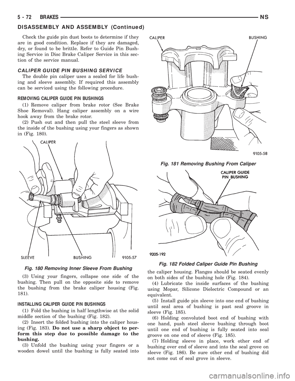
(2) Push out and then pull the steel sleeve from
the inside of the bushing using your fingers as shown
in (Fig. 180).
(3) Using your fingers, collapse one side of the
bushing. Then pull on the opposite side to remove
the bushing from the brake caliper housing (Fig.
181).
INSTALLING CALIPER GUIDE PIN BUSHINGS
(1) Fold the bushing in half lengthwise at the solid
middle section of the bushing (Fig. 182).
(2) Insert the folded bushing into the caliper hous-
ing (Fig. 183).Do not use a sharp object to per-
form this step due to possible damage to the
bushing.
(3) Unfold the bushing using your fingers or a
wooden dowel until the bushing is fully seated intothe caliper housing. Flanges should be seated evenly
on both sides of the bushing hole (Fig. 184).
(4) Lubricate the inside surfaces of the bushing
using Mopar, Silicone Dielectric Compound or an
equivalent.
(5) Install guide pin sleeve into one end of bushing
until seal area of bushing is past seal groove in
sleeve (Fig. 185).
(6) Holding convoluted boot end of bushing with
one hand, push steel sleeve bushing through boot
until one end of bushing is fully seated into seal
groove on one end of sleeve (Fig. 185).
(7) Holding sleeve in place, work other end of
bushing over end of sleeve and into the seal grove on
sleeve (Fig. 186). Be sure other end of bushing did
not come out of seal grove in sleeve.
Fig. 180 Removing Inner Sleeve From Bushing
Fig. 181 Removing Bushing From Caliper
Fig. 182 Folded Caliper Guide Pin Bushing
5 - 72 BRAKESNS
DISASSEMBLY AND ASSEMBLY (Continued)
Page 156 of 1938
from rotor, so hydraulic fluid cannot get on rotor.
Place a small piece of wood between the piston and
caliper fingers.
(2)Carefullydepress brake pedal to hydraulically
push piston out of bore. Then apply and hold down
the brake pedal to any position beyond the first inch
of pedal travel. This will prevent loss of brake fluid
from the master cylinder.
(3) If both front caliper pistons are to be removed,
disconnect brake tube at flexible brake hose at frame
rail. Plug brake tube and remove piston from oppo-
site caliper using the same process as above for the
first piston removal.
(4) Disconnect the brake fluid flex hose from the
caliper assembly.
CAUTION: Do not use excessive force when clamp-
ing caliper in vise. Excessive vise pressure will
cause bore distortion and binding of piston.
(5) To disassemble caliper, mount in a vise
equipped with protective jaws.
(6) Remove guide pin sleeves and guide pin bush-
ings. See Removing Guide Pin Bushings in the cali-
per disassembly section of this manual.
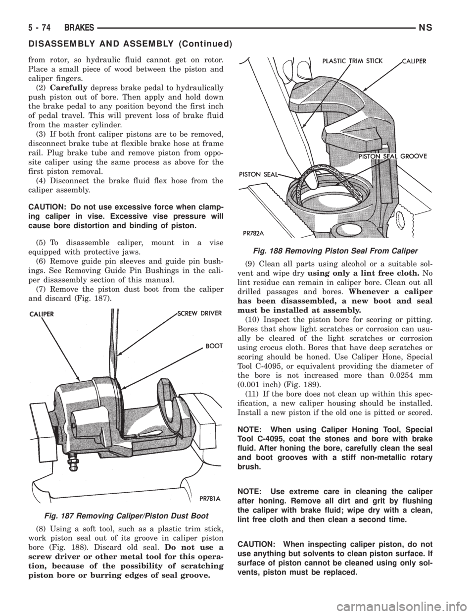
(7) Remove the piston dust boot from the caliper
and discard (Fig. 187).
(8) Using a soft tool, such as a plastic trim stick,
work piston seal out of its groove in caliper piston
bore (Fig. 188). Discard old seal.Do not use a
screw driver or other metal tool for this opera-
tion, because of the possibility of scratching
piston bore or burring edges of seal groove.(9) Clean all parts using alcohol or a suitable sol-
vent and wipe dryusing only a lint free cloth.No
lint residue can remain in caliper bore. Clean out all
drilled passages and bores.Whenever a caliper
has been disassembled, a new boot and seal
must be installed at assembly.
(10) Inspect the piston bore for scoring or pitting.
Bores that show light scratches or corrosion can usu-
ally be cleared of the light scratches or corrosion
using crocus cloth. Bores that have deep scratches or
scoring should be honed. Use Caliper Hone, Special
Tool C-4095, or equivalent providing the diameter of
the bore is not increased more than 0.0254 mm
(0.001 inch) (Fig. 189).
(11) If the bore does not clean up within this spec-
ification, a new caliper housing should be installed.
Install a new piston if the old one is pitted or scored.
NOTE: When using Caliper Honing Tool, Special
Tool C-4095, coat the stones and bore with brake
fluid. After honing the bore, carefully clean the seal
and boot grooves with a stiff non-metallic rotary
brush.
NOTE: Use extreme care in cleaning the caliper
after honing. Remove all dirt and grit by flushing
the caliper with brake fluid; wipe dry with a clean,
lint free cloth and then clean a second time.
CAUTION: When inspecting caliper piston, do not
use anything but solvents to clean piston surface. If
surface of piston cannot be cleaned using only sol-
vents, piston must be replaced.
Fig. 187 Removing Caliper/Piston Dust Boot
Fig. 188 Removing Piston Seal From Caliper
5 - 74 BRAKESNS
DISASSEMBLY AND ASSEMBLY (Continued)