differential CHRYSLER VOYAGER 1996 User Guide
[x] Cancel search | Manufacturer: CHRYSLER, Model Year: 1996, Model line: VOYAGER, Model: CHRYSLER VOYAGER 1996Pages: 1938, PDF Size: 55.84 MB
Page 1522 of 1938
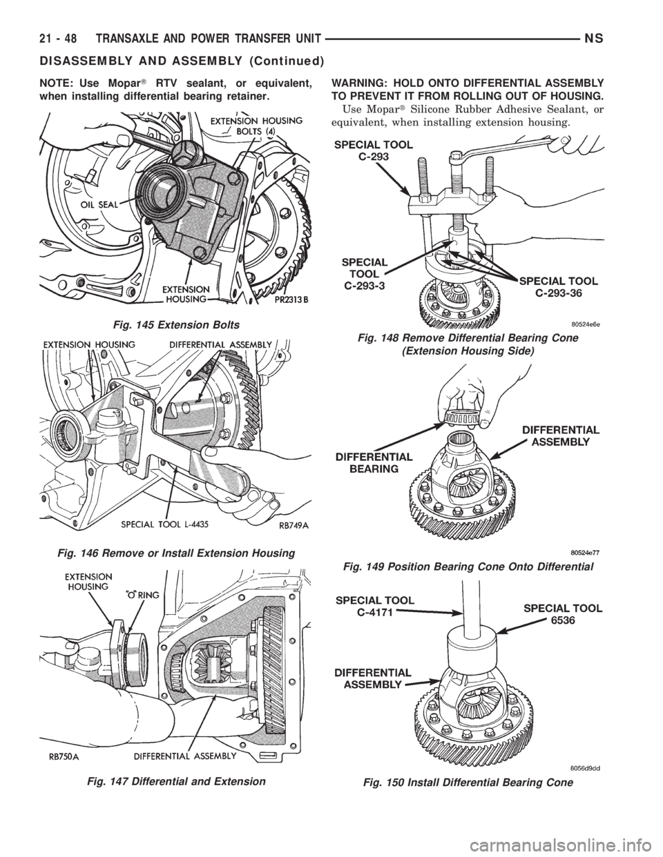
NOTE: Use MoparTRTV sealant, or equivalent,
when installing differential bearing retainer.WARNING: HOLD ONTO DIFFERENTIAL ASSEMBLY
TO PREVENT IT FROM ROLLING OUT OF HOUSING.
Use MopartSilicone Rubber Adhesive Sealant, or
equivalent, when installing extension housing.
Fig. 145 Extension Bolts
Fig. 146 Remove or Install Extension Housing
Fig. 147 Differential and Extension
Fig. 148 Remove Differential Bearing Cone
(Extension Housing Side)
Fig. 149 Position Bearing Cone Onto Differential
Fig. 150 Install Differential Bearing Cone
21 - 48 TRANSAXLE AND POWER TRANSFER UNITNS
DISASSEMBLY AND ASSEMBLY (Continued)
Page 1523 of 1938
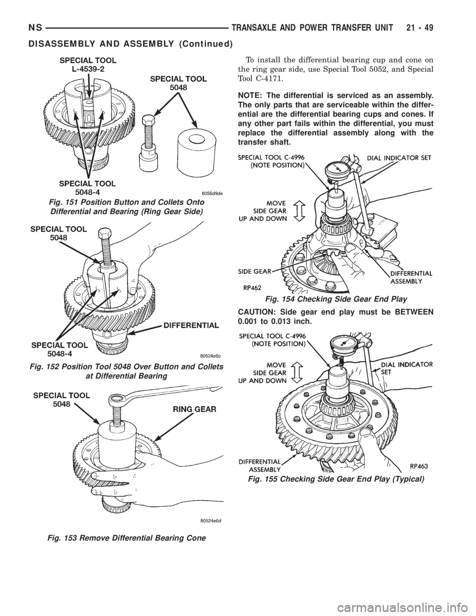
To install the differential bearing cup and cone on
the ring gear side, use Special Tool 5052, and Special
Tool C-4171.
NOTE: The differential is serviced as an assembly.
The only parts that are serviceable within the differ-
ential are the differential bearing cups and cones. If
any other part fails within the differential, you must
replace the differential assembly along with the
transfer shaft.
CAUTION: Side gear end play must be BETWEEN
0.001 to 0.013 inch.
Fig. 151 Position Button and Collets Onto
Differential and Bearing (Ring Gear Side)
Fig. 152 Position Tool 5048 Over Button and Collets
at Differential Bearing
Fig. 153 Remove Differential Bearing Cone
Fig. 154 Checking Side Gear End Play
Fig. 155 Checking Side Gear End Play (Typical)
NSTRANSAXLE AND POWER TRANSFER UNIT 21 - 49
DISASSEMBLY AND ASSEMBLY (Continued)
Page 1524 of 1938
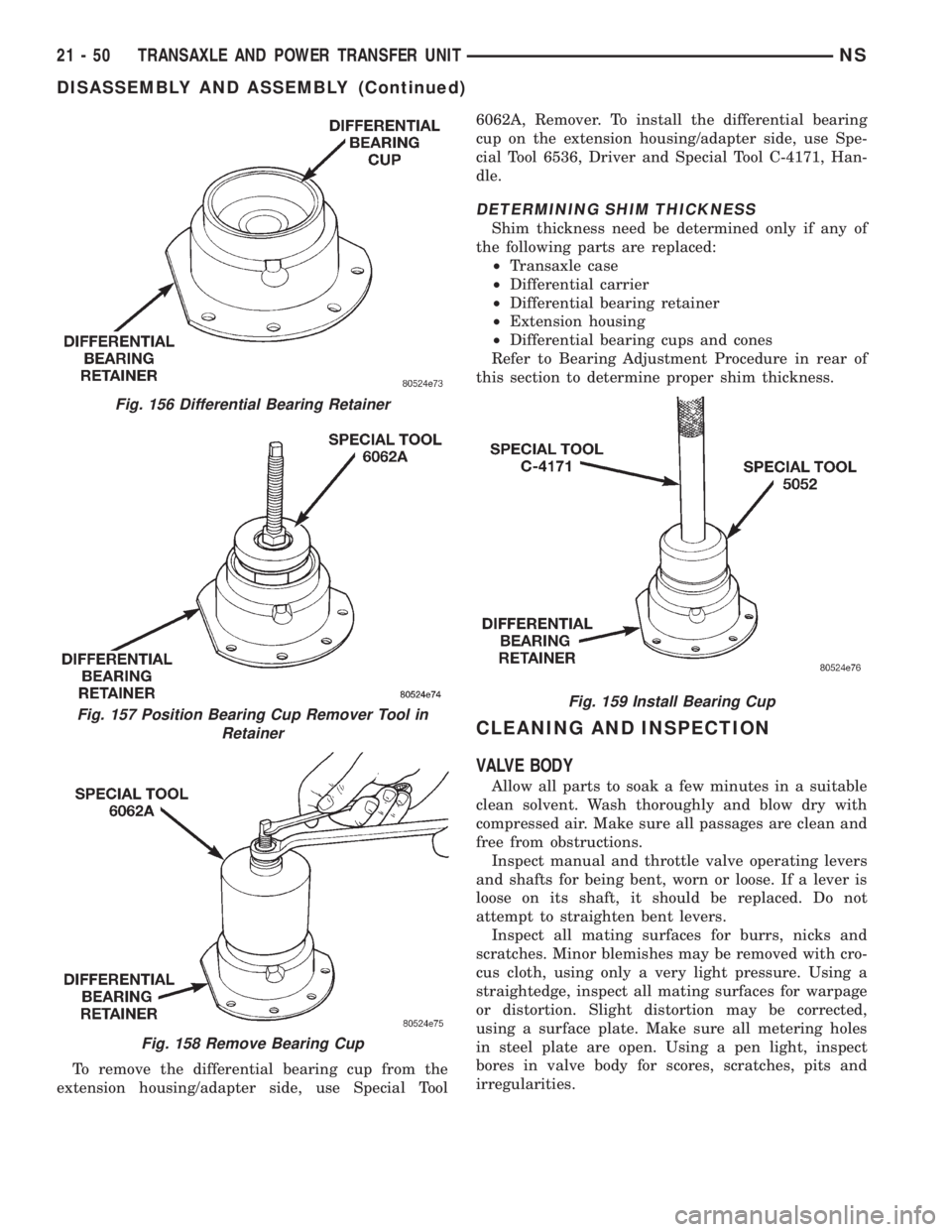
To remove the differential bearing cup from the
extension housing/adapter side, use Special Tool6062A, Remover. To install the differential bearing
cup on the extension housing/adapter side, use Spe-
cial Tool 6536, Driver and Special Tool C-4171, Han-
dle.
DETERMINING SHIM THICKNESS
Shim thickness need be determined only if any of
the following parts are replaced:
²Transaxle case
²Differential carrier
²Differential bearing retainer
²Extension housing
²Differential bearing cups and cones
Refer to Bearing Adjustment Procedure in rear of
this section to determine proper shim thickness.
CLEANING AND INSPECTION
VALVE BODY
Allow all parts to soak a few minutes in a suitable
clean solvent. Wash thoroughly and blow dry with
compressed air. Make sure all passages are clean and
free from obstructions.
Inspect manual and throttle valve operating levers
and shafts for being bent, worn or loose. If a lever is
loose on its shaft, it should be replaced. Do not
attempt to straighten bent levers.
Inspect all mating surfaces for burrs, nicks and
scratches. Minor blemishes may be removed with cro-
cus cloth, using only a very light pressure. Using a
straightedge, inspect all mating surfaces for warpage
or distortion. Slight distortion may be corrected,
using a surface plate. Make sure all metering holes
in steel plate are open. Using a pen light, inspect
bores in valve body for scores, scratches, pits and
irregularities.
Fig. 156 Differential Bearing Retainer
Fig. 157 Position Bearing Cup Remover Tool in
Retainer
Fig. 158 Remove Bearing Cup
Fig. 159 Install Bearing Cup
21 - 50 TRANSAXLE AND POWER TRANSFER UNITNS
DISASSEMBLY AND ASSEMBLY (Continued)
Page 1527 of 1938
hold the shims in place. Install the output shaft gear
and bearing assembly.
(13) Install the retaining nut and washer and
torque to 271 N´m (200 ft. lbs.).
(14) Using an inch-pound torque wrench, check the
turning torque.The torque should be between 3
and 8 inch-pounds.
(15) If the turning torque is too high, install a
.05mm (.002 inch) thicker shim. If the turning torque
is too low, install a .05 mm (.002 inch) thinner shim.
Repeat until the proper turning torque is 3 to 8 inch
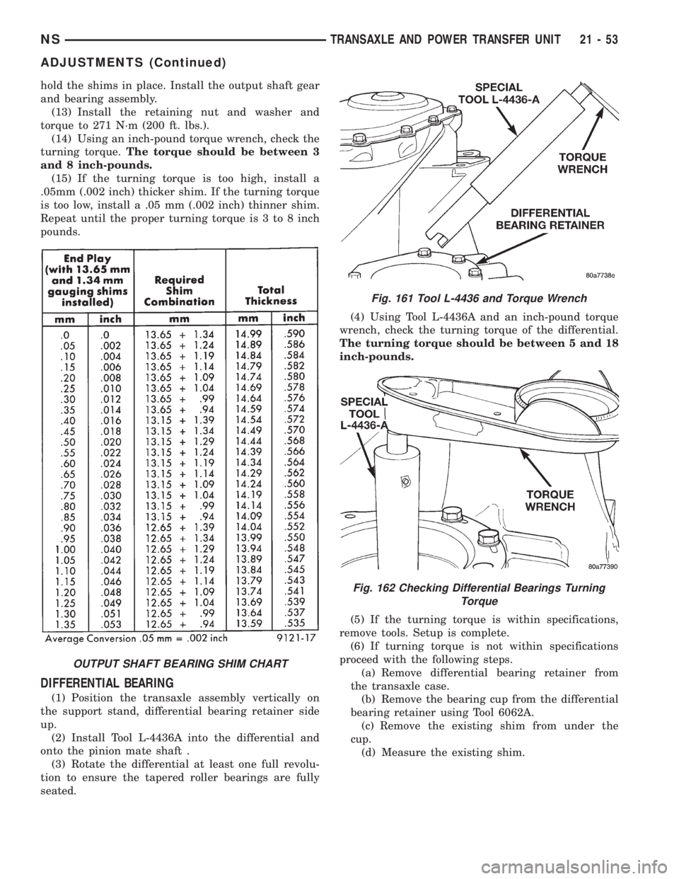
pounds.
DIFFERENTIAL BEARING
(1) Position the transaxle assembly vertically on
the support stand, differential bearing retainer side
up.
(2) Install Tool L-4436A into the differential and
onto the pinion mate shaft .
(3) Rotate the differential at least one full revolu-
tion to ensure the tapered roller bearings are fully
seated.(4) Using Tool L-4436A and an inch-pound torque
wrench, check the turning torque of the differential.
The turning torque should be between 5 and 18
inch-pounds.
(5) If the turning torque is within specifications,
remove tools. Setup is complete.
(6) If turning torque is not within specifications
proceed with the following steps.
(a) Remove differential bearing retainer from
the transaxle case.
(b) Remove the bearing cup from the differential
bearing retainer using Tool 6062A.
(c) Remove the existing shim from under the
cup.
(d) Measure the existing shim.
OUTPUT SHAFT BEARING SHIM CHART
Fig. 161 Tool L-4436 and Torque Wrench
Fig. 162 Checking Differential Bearings Turning
Torque
NSTRANSAXLE AND POWER TRANSFER UNIT 21 - 53
ADJUSTMENTS (Continued)
Page 1528 of 1938
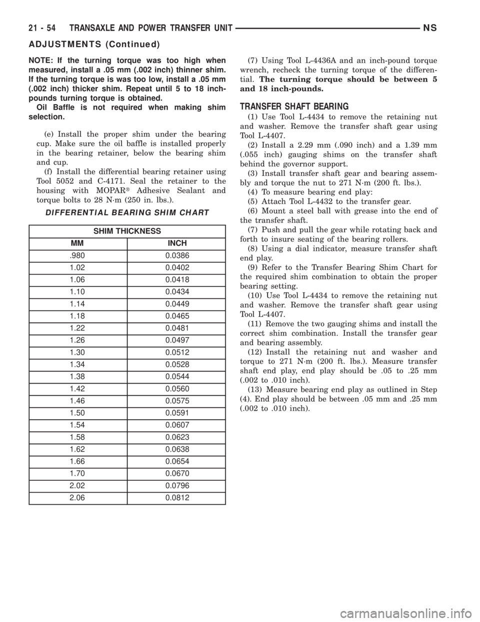
NOTE: If the turning torque was too high when
measured, install a .05 mm (.002 inch) thinner shim.
If the turning torque is was too low, install a .05 mm
(.002 inch) thicker shim. Repeat until 5 to 18 inch-
pounds turning torque is obtained.
Oil Baffle is not required when making shim
selection.
(e) Install the proper shim under the bearing
cup. Make sure the oil baffle is installed properly
in the bearing retainer, below the bearing shim
and cup.
(f) Install the differential bearing retainer using
Tool 5052 and C-4171. Seal the retainer to the
housing with MOPARtAdhesive Sealant and
torque bolts to 28 N´m (250 in. lbs.).(7) Using Tool L-4436A and an inch-pound torque
wrench, recheck the turning torque of the differen-
tial.The turning torque should be between 5
and 18 inch-pounds.
TRANSFER SHAFT BEARING
(1) Use Tool L-4434 to remove the retaining nut
and washer. Remove the transfer shaft gear using
Tool L-4407.
(2) Install a 2.29 mm (.090 inch) and a 1.39 mm
(.055 inch) gauging shims on the transfer shaft
behind the governor support.
(3) Install transfer shaft gear and bearing assem-
bly and torque the nut to 271 N´m (200 ft. lbs.).
(4) To measure bearing end play:
(5) Attach Tool L-4432 to the transfer gear.
(6) Mount a steel ball with grease into the end of
the transfer shaft.
(7) Push and pull the gear while rotating back and
forth to insure seating of the bearing rollers.
(8) Using a dial indicator, measure transfer shaft
end play.
(9) Refer to the Transfer Bearing Shim Chart for
the required shim combination to obtain the proper
bearing setting.
(10) Use Tool L-4434 to remove the retaining nut
and washer. Remove the transfer shaft gear using
Tool L-4407.
(11) Remove the two gauging shims and install the
correct shim combination. Install the transfer gear
and bearing assembly.
(12) Install the retaining nut and washer and
torque to 271 N´m (200 ft. lbs.). Measure transfer
shaft end play, end play should be .05 to .25 mm
(.002 to .010 inch).
(13) Measure bearing end play as outlined in Step
(4). End play should be between .05 mm and .25 mm
(.002 to .010 inch).
DIFFERENTIAL BEARING SHIM CHART
SHIM THICKNESS
MM INCH
.980 0.0386
1.02 0.0402
1.06 0.0418
1.10 0.0434
1.14 0.0449
1.18 0.0465
1.22 0.0481
1.26 0.0497
1.30 0.0512
1.34 0.0528
1.38 0.0544
1.42 0.0560
1.46 0.0575
1.50 0.0591
1.54 0.0607
1.58 0.0623
1.62 0.0638
1.66 0.0654
1.70 0.0670
2.02 0.0796
2.06 0.0812
21 - 54 TRANSAXLE AND POWER TRANSFER UNITNS
ADJUSTMENTS (Continued)
Page 1538 of 1938
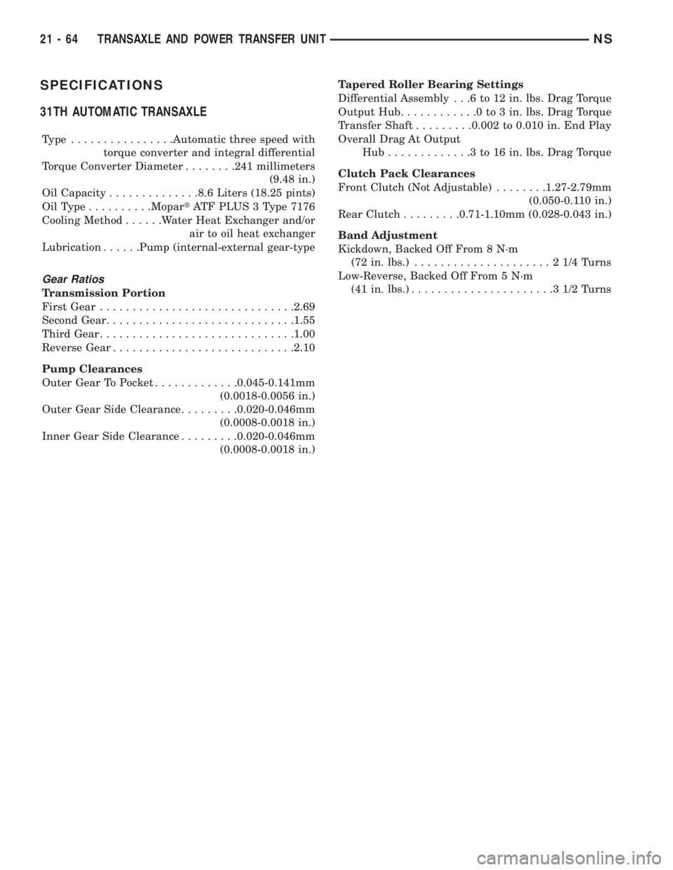
SPECIFICATIONS
31TH AUTOMATIC TRANSAXLE
Type ................Automatic three speed with
torque converter and integral differential
Torque Converter Diameter........241 millimeters
(9.48 in.)
Oil Capacity..............8.6 Liters (18.25 pints)
OilType..........MopartATF PLUS 3 Type 7176
Cooling Method......Water Heat Exchanger and/or
air to oil heat exchanger
Lubrication......Pump (internal-external gear-type
Gear Ratios
Transmission Portion
First Gear..............................2.69
Second Gear.............................1.55
Third Gear..............................1.00
Reverse Gear............................2.10
Pump Clearances
Outer Gear To Pocket.............0.045-0.141mm
(0.0018-0.0056 in.)
Outer Gear Side Clearance.........0.020-0.046mm
(0.0008-0.0018 in.)
Inner Gear Side Clearance.........0.020-0.046mm
(0.0008-0.0018 in.)Tapered Roller Bearing Settings
Differential Assembly . . .6 to 12 in. lbs. Drag Torque
Output Hub............0to3in.lbs. Drag Torque
Transfer Shaft.........0.002 to 0.010 in. End Play
Overall Drag At Output
Hub.............3to16in.lbs. Drag Torque
Clutch Pack Clearances
Front Clutch (Not Adjustable)........1.27-2.79mm
(0.050-0.110 in.)
Rear Clutch.........0.71-1.10mm (0.028-0.043 in.)
Band Adjustment
Kickdown, Backed Off From 8 N´m
(72 in. lbs.).....................21/4Turns
Low-Reverse, Backed Off From 5 N´m
(41 in. lbs.)......................31/2Turns
21 - 64 TRANSAXLE AND POWER TRANSFER UNITNS
Page 1543 of 1938
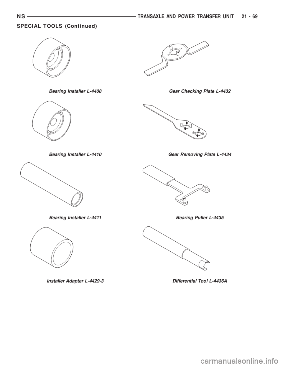
Bearing Installer L-4408
Bearing Installer L-4410
Bearing Installer L-4411
Installer Adapter L-4429-3
Gear Checking Plate L-4432
Gear Removing Plate L-4434
Bearing Puller L-4435
Differential Tool L-4436A
NSTRANSAXLE AND POWER TRANSFER UNIT 21 - 69
SPECIAL TOOLS (Continued)
Page 1545 of 1938
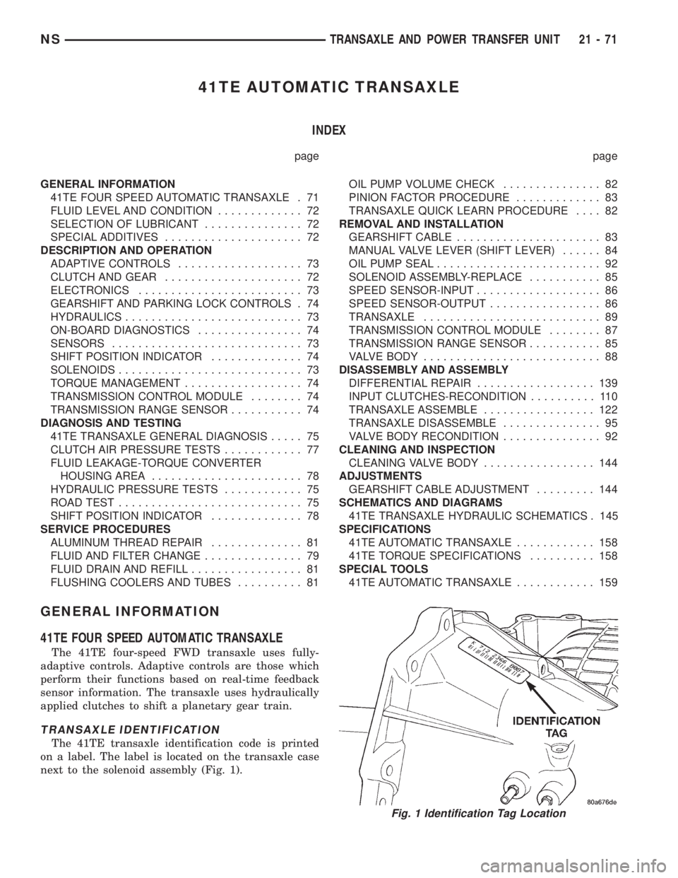
41TE AUTOMATIC TRANSAXLE
INDEX
page page
GENERAL INFORMATION
41TE FOUR SPEED AUTOMATIC TRANSAXLE . 71
FLUID LEVEL AND CONDITION............. 72
SELECTION OF LUBRICANT............... 72
SPECIAL ADDITIVES..................... 72
DESCRIPTION AND OPERATION
ADAPTIVE CONTROLS................... 73
CLUTCH AND GEAR..................... 72
ELECTRONICS......................... 73
GEARSHIFT AND PARKING LOCK CONTROLS . 74
HYDRAULICS........................... 73
ON-BOARD DIAGNOSTICS................ 74
SENSORS............................. 73
SHIFT POSITION INDICATOR.............. 74
SOLENOIDS............................ 73
TORQUE MANAGEMENT.................. 74
TRANSMISSION CONTROL MODULE........ 74
TRANSMISSION RANGE SENSOR........... 74
DIAGNOSIS AND TESTING
41TE TRANSAXLE GENERAL DIAGNOSIS..... 75
CLUTCH AIR PRESSURE TESTS............ 77
FLUID LEAKAGE-TORQUE CONVERTER
HOUSING AREA....................... 78
HYDRAULIC PRESSURE TESTS............ 75
ROAD TEST............................ 75
SHIFT POSITION INDICATOR.............. 78
SERVICE PROCEDURES
ALUMINUM THREAD REPAIR.............. 81
FLUID AND FILTER CHANGE............... 79
FLUID DRAIN AND REFILL................. 81
FLUSHING COOLERS AND TUBES.......... 81OIL PUMP VOLUME CHECK............... 82
PINION FACTOR PROCEDURE............. 83
TRANSAXLE QUICK LEARN PROCEDURE.... 82
REMOVAL AND INSTALLATION
GEARSHIFT CABLE...................... 83
MANUAL VALVE LEVER (SHIFT LEVER)...... 84
OIL PUMP SEAL......................... 92
SOLENOID ASSEMBLY-REPLACE........... 85
SPEED SENSOR-INPUT................... 86
SPEED SENSOR-OUTPUT................. 86
TRANSAXLE........................... 89
TRANSMISSION CONTROL MODULE........ 87
TRANSMISSION RANGE SENSOR........... 85
VALVE BODY........................... 88
DISASSEMBLY AND ASSEMBLY
DIFFERENTIAL REPAIR.................. 139
INPUT CLUTCHES-RECONDITION.......... 110
TRANSAXLE ASSEMBLE................. 122
TRANSAXLE DISASSEMBLE............... 95
VALVE BODY RECONDITION............... 92
CLEANING AND INSPECTION
CLEANING VALVE BODY................. 144
ADJUSTMENTS
GEARSHIFT CABLE ADJUSTMENT......... 144
SCHEMATICS AND DIAGRAMS
41TE TRANSAXLE HYDRAULIC SCHEMATICS . 145
SPECIFICATIONS
41TE AUTOMATIC TRANSAXLE............ 158
41TE TORQUE SPECIFICATIONS.......... 158
SPECIAL TOOLS
41TE AUTOMATIC TRANSAXLE............ 159
GENERAL INFORMATION
41TE FOUR SPEED AUTOMATIC TRANSAXLE
The 41TE four-speed FWD transaxle uses fully-
adaptive controls. Adaptive controls are those which
perform their functions based on real-time feedback
sensor information. The transaxle uses hydraulically
applied clutches to shift a planetary gear train.
TRANSAXLE IDENTIFICATION
The 41TE transaxle identification code is printed
on a label. The label is located on the transaxle case
next to the solenoid assembly (Fig. 1).
Fig. 1 Identification Tag Location
NSTRANSAXLE AND POWER TRANSFER UNIT 21 - 71
Page 1546 of 1938

OPERATION
The gear ratios for the 41TE transaxle are as fol-
lows:
²1stÐ2.84
²2ndÐ1.57
²3rdÐ1.00
²ODÐ0.69
²ReverseÐ2.21
Final Drive Ratio is dependent on which engine
option is selected.
²2.4 Liter: 3.91 FDR
²3.3 Liter: 3.62 FDR
²3.8 Liter: 3.45 FDR
The torque converter clutch is available in 2nd,
direct, or overdrive gear;. The shift lever is conven-
tional with six positions: P, R, N, OD, 3, and L avail-
able. When OD is selected the transaxle shifts
through all four speeds with torque converter clutch
available in overdrive. This position is recommended
for most driving. The 3 position is tailored for use in
hilly or mountainous driving. When 3 is selected, the
transmission uses only 1st, 2nd, and direct gears
with 2nd-direct shift delayed to 40 mph or greater.
When operating in 3 or L positions torque converter
clutch application occurs in direct gear. This
improves transmission cooling under heavy loads. If
high engine coolant temperature occurs, the torque
converter clutch will also engage in 2nd gear. The L
position provides maximum engine braking for
descending steep grades. Unlike most current tran-
saxles, upshifts are provided to 2nd or direct gear at
peak engine speeds if the accelerator is depressed.
This provides engine over-speed protection and max-
imum performance.
FLUID LEVEL AND CONDITION
NOTE: The transmission and differential sump have
a common oil sump with an opening between the
two.
The torque converter fills in both the (P) Park and
(N) Neutral positions. Place the selector lever in (P)
Park to check the fluid level.The engine should be
running at idle speed for at least one minute,
with the vehicle on level ground. This will
assure complete oil level stabilization between
differential and transmission.The fluid should be
at normal operating temperature (approximately 82
C. or 180 F.). The fluid level is correct if it is in the
HOTregion (cross-hatched area) on the oil level indi-
cator.
Low fluid level can cause a variety of conditions
because it allows the pump to take in air along with
the fluid. As in any hydraulic system, air bubbles
make the fluid spongy, therefore, pressures will be
low and build up slowly.Improper filling can also raise the fluid level too
high. When the transaxle has too much fluid, the
gears churn up foam and cause the same conditions
which occur with a low fluid level.
In either case, the air bubbles can cause overheat-
ing, fluid oxidation, and varnishing. This can inter-
fere with normal valve, clutch, and accumulator
operation. Foaming can also result in fluid escaping
from the transaxle vent where it may be mistaken
for a leak.
Along with fluid level, it is important to check the
condition of the fluid. When the fluid smells burned,
and is contaminated with metal or friction material
particles, a complete transaxle overhaul is needed.
Be sure to examine the fluid on the dipstick closely.
If there is any doubt about its condition, drain out a
sample for a double check.
After the fluid has been checked, seat the dipstick
fully to seal out water and dirt.
SELECTION OF LUBRICANT
It is important that the proper lubricant be used in
the 41TE transaxle. MOPARtATF PLUS 3 (Auto-
matic Transmission FluidÐtype 7176) should be used
to aid in assuring optimum transmission perfor-
mance. Fluids of the type labeled DEXRON II Auto-
matic Transmission Fluid arenot recommended.It
is important that the transmission fluid be main-
tained at the prescribed level using the recommended
fluids.
SPECIAL ADDITIVES
Chrysler Corporation does not recommend the
addition of any fluids to the transaxle, other than the
fluid listed above. An exception to this policy is the
use of special dyes to aid in detecting fluid leaks. The
use of transmission sealers should be avoided, since
they may adversely affect seals.
DESCRIPTION AND OPERATION
CLUTCH AND GEAR
The transaxle consists of:
²Three multiple disc input clutches
²Two multiple disc grounded clutches
²Four hydraulic accumulators
²Two planetary gear sets
This provides four forward ratios and a reverse
ratio. The input clutch-apply pistons were designed
with centrifugally balanced oil cavities so that quick
response and good control can be achieved at any
speed. A push/pull piston is incorporated for two of
the three input clutches.
21 - 72 TRANSAXLE AND POWER TRANSFER UNITNS
GENERAL INFORMATION (Continued)
Page 1613 of 1938

(1) Install transaxle solenoid pack (Fig. 284).
(2) Install input and output speed sensors.
This concludes the assembly of the transaxle cen-
terline.
DIFFERENTIAL REPAIR
NOTE: The differential is serviced as an assembly.
The only parts that are serviceable within the differ-
ential are the differential bearing cups and cones. If
any other part fails within the differential, you must
replace the differential assembly along with the
transfer shaft.
DISASSEMBLE
The transfer shaft should be removed for differen-
tial repair and bearing turning torque checking.
(1) Remove the differential cover and bolts (Fig.
285) (Fig. 286).
(2) Remove the differential bearing retainer and
bolts (Fig. 287) (Fig. 288).(3) Using a plastic hammer, remove extension
housing/adapter plate on the right side of the tran-
saxle.
Fig. 283 Install Pan Bolts
Fig. 284 Install Solenoid Pack
Fig. 285 Differential Cover Bolts
Fig. 286 Remove Differential Cover
Fig. 287 Differential Retainer Bolts
NSTRANSAXLE AND POWER TRANSFER UNIT 21 - 139
DISASSEMBLY AND ASSEMBLY (Continued)