maintenance schedule CHRYSLER VOYAGER 1996 User Guide
[x] Cancel search | Manufacturer: CHRYSLER, Model Year: 1996, Model line: VOYAGER, Model: CHRYSLER VOYAGER 1996Pages: 1938, PDF Size: 55.84 MB
Page 1225 of 1938

HYDRAULIC TAPPETS
Before disassembling any part of the engine to cor-
rect tappet noise, check the oil pressure. If vehicle
has no oil pressure gauge, install a reliable gauge at
the pressure sending unit. The pressure should be
between 3.5 bars to 5.0 bars at 4000 RPM.
Check the oil level after the engine reaches normal
operating temperature. Allow 5 minutes to stabilize
oil level, check dipstick. The oil level in the pan
should never be above the FULL mark or below the
ADD OIL mark on dipstick. Either of these 2 condi-
tions could be responsible for noisy tappets.
OIL LEVEL HIGH
If oil level is above the FULL mark, it is possible
for the connecting rods to dip into the oil. With the
engine running, this condition could create foam in
the oil pan. Foam in oil pan would be fed to the
hydraulic tappets by the oil pump causing them to
lose length and allow valves to seat noisily.
OIL LEVEL LOW
Low oil level may allow oil pump to take in air.
When air is fed to the tappets, they lose length which
allows valves to seat noisily. Any leaks on intake side
of oil pump through which air can be drawn will cre-
ate the same tappet action. Check the lubrication
system from the intake strainer to the pump cover,
including the relief valve retainer cap. When tappet
noise is due to aeration, it may be intermittent or
constant, and usually more than 1 tappet will be
noisy. When oil level and leaks have been corrected,
operate the engine at fast idle. Run engine for a suf-
ficient time to allow all of the air inside the tappets
to be bled out.
TAPPET NOISE DIAGNOSIS
(1) To determine source of tappet noise, operate
engine at idle with cylinder head covers removed.
(2) Feel each valve spring or rocker arm to detect
noisy tappet. The noisy tappet will cause the affected
spring and/or rocker arm to vibrate or feel rough in
operation.
NOTE: Worn valve guides or cocked springs are
sometimes mistaken for noisy tappets. If such is
the case, noise may be dampened by applying side
thrust on the valve spring. If noise is not apprecia-
bly reduced, it can be assumed the noise is in the
tappet. Inspect the rocker arm push rod sockets
and push rod ends for wear.
(3) Valve tappet noise ranges from light noise to a
heavy click. A light noise is usually caused by exces-
sive leak down around the unit plunger or by the
plunger partially sticking in the tappet body cylinder.
The tappet should be replaced. A heavy click iscaused by a tappet check valve not seating or by for-
eign particles becoming wedged between the plunger
and the tappet body. This will cause the plunger to
stick in the down position. This heavy click will be
accompanied by excessive clearance between the
valve stem and rocker arm as valve closes. In either
case, tappet assembly should be removed for inspec-
tion and cleaning.
(4) The valve train generates a noise very much
like a light tappet noise during normal operation.
Care must be taken to ensure that tappets are mak-
ing the noise. In general, if more than one tappet
seems to be noisy, its probably not the tappets.
SERVICE PROCEDURES
CHECKING OIL LEVEL
To assure proper engine lubrication, the engine oil
must be maintained at the correct level. Check the
oil level at regular intervals, such as every fuel stop.
The best time to check the oil level is about 5 min-
utes after a fully warmed-up engine is shut off, or
before starting the vehicle after it has sat overnight.
Checking the oil while the vehicle is on level
ground, will improve the accuracy of the oil level
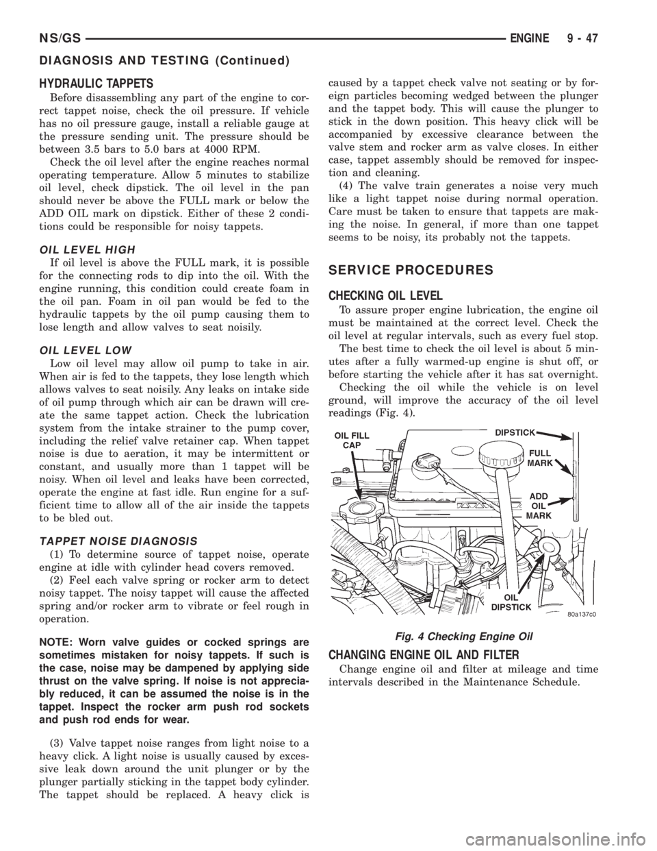
readings (Fig. 4).
CHANGING ENGINE OIL AND FILTER
Change engine oil and filter at mileage and time
intervals described in the Maintenance Schedule.
Fig. 4 Checking Engine Oil
NS/GSENGINE 9 - 47
DIAGNOSIS AND TESTING (Continued)
Page 1263 of 1938

EXHAUST SYSTEM AND INTAKE MANIFOLD
CONTENTS
page page
GENERAL INFORMATION
CATALYTIC CONVERTERS................. 1
EXHAUST FLEX-JOINT COUPLING........... 2
EXHAUST GAS RECIRCULATION (EGR)....... 2
EXHAUST SYSTEM....................... 1
HEAT SHIELDS.......................... 2
DESCRIPTION AND OPERATION
INTAKE/EXHAUST MANIFOLDÐ2.4L ENGINE . . 3
INTAKE/EXHAUST MANIFOLDÐ3.0L ENGINE . . 3
INTAKE/EXHAUST MANIFOLDÐ3.3/3.8L
ENGINES............................. 3
DIAGNOSIS AND TESTING
EXHAUST SYSTEM....................... 3REMOVAL AND INSTALLATION
EXHAUST MANIFOLDÐ2.4L ENGINE........ 8
EXHAUST MANIFOLDÐ3.0L ENGINE....... 11
EXHAUST MANIFOLDSÐ3.3/3.8L ENGINE . . . 16
EXHAUST PIPES, MUFFLERS AND TAILPIPES . 4
INTAKE MANIFOLD LOWERÐ2.4L ENGINE.... 6
INTAKE MANIFOLDÐ3.0L ENGINE.......... 8
INTAKE MANIFOLDÐ3.3/3.8L ENGINE...... 12
UPPER INTAKE MANIFOLDÐ2.4L ENGINE.... 4
CLEANING AND INSPECTION
EXHAUST MANIFOLD.................... 17
INTAKE MANIFOLD...................... 17
SPECIFICATIONS
TORQUE CHART........................ 18
GENERAL INFORMATION
EXHAUST SYSTEM
The exhaust systems are produced in several con-
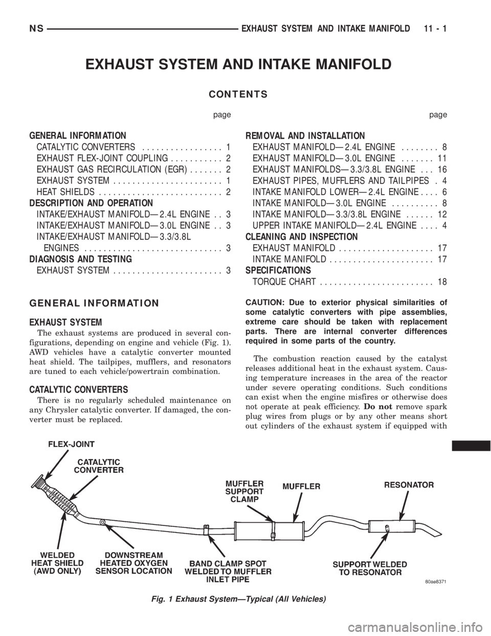
figurations, depending on engine and vehicle (Fig. 1).
AWD vehicles have a catalytic converter mounted
heat shield. The tailpipes, mufflers, and resonators
are tuned to each vehicle/powertrain combination.
CATALYTIC CONVERTERS
There is no regularly scheduled maintenance on
any Chrysler catalytic converter. If damaged, the con-
verter must be replaced.CAUTION: Due to exterior physical similarities of
some catalytic converters with pipe assemblies,
extreme care should be taken with replacement
parts. There are internal converter differences
required in some parts of the country.
The combustion reaction caused by the catalyst
releases additional heat in the exhaust system. Caus-
ing temperature increases in the area of the reactor
under severe operating conditions. Such conditions
can exist when the engine misfires or otherwise does
not operate at peak efficiency.Do notremove spark
plug wires from plugs or by any other means short
out cylinders of the exhaust system if equipped with
Fig. 1 Exhaust SystemÐTypical (All Vehicles)
NSEXHAUST SYSTEM AND INTAKE MANIFOLD 11 - 1
Page 1298 of 1938

FUEL DELIVERY SYSTEM
INDEX
page page
DESCRIPTION AND OPERATION
FUEL DELIVERY SYSTEM.................. 4
FUEL INJECTORS........................ 5
FUEL LEVEL SENSOR..................... 5
FUEL PRESSURE REGULATOR.............. 5
FUEL PUMP MODULE..................... 4
FUEL TANK............................. 5
PRESSURE-VACUUM FILLER CAP........... 6
QUICK-CONNECT FITTINGS................ 6
DIAGNOSIS AND TESTING
FUEL INJECTORS........................ 9
FUEL LEVEL SENSOR..................... 9
FUEL PUMP PRESSURE TEST 2.4/3.3/3.8L..... 6
SERVICE PROCEDURES
FUEL SYSTEM PRESSURE RELEASE
PROCEDUREÐ2.4/3.3/3.8L............... 11
FUEL SYSTEM PRESSURE RELEASE
PROCEDUREÐ3.0L ENGINE............. 11
HOSES AND CLAMPS.................... 12QUICK-CONNECT FITTINGS............... 12
REMOVAL AND INSTALLATION
ACCELERATOR PEDAL................... 26
FUEL FILTER........................... 12
FUEL INJECTOR RAILÐ2.4L............... 18
FUEL INJECTOR RAILÐ3.0L............... 19
FUEL INJECTOR RAILÐ3.3/3.8L............ 21
FUEL INJECTORSÐ3.0L.................. 25
FUEL INJECTORÐ2.4L................... 24
FUEL INJECTORÐ3.3/3.8L................. 26
FUEL LEVEL SENSOR.................... 15
FUEL PRESSURE REGULATOR............. 14
FUEL PUMP INLET STRAINER............. 15
FUEL PUMP MODULE.................... 13
FUEL TANK............................ 17
THROTTLE CABLE...................... 27
SPECIFICATIONS
FUEL TANK CAPACITY................... 28
TORQUE.............................. 28
DESCRIPTION AND OPERATION
FUEL DELIVERY SYSTEM
The front wheel drive van uses a plastic fuel tank
located on the left side of the vehicle.
The Fuel Delivery System consists of: the electric
fuel pump module, fuel filter, tubes/lines/hoses, fuel
rail, and fuel injectors.
The in-tank fuel pump module contains the fuel
pump and pressure regulator. The pump is serviced
as part of the fuel pump module. Refer to Fuel Pump
Module.
The fuel filter is a replaceable in-line filter. The fil-
ter attaches to a bracket mounted on top of the fuel
tank. Refer to the Maintenance Schedules in the
Introduction section of this manual for recommended
fuel filter replacement intervals.
A returnless fuel system is used on all vehicles.
Fuel is returned through the fuel pump module and
back to the fuel tank. A separate fuel return line
from the tank to the engine is no longer used.
FUEL PUMP MODULE
The fuel pump module is installed in the top of the
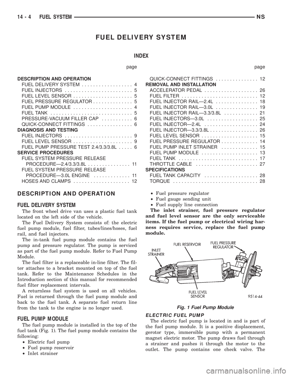
fuel tank (Fig. 1). The fuel pump module contains the
following:
²Electric fuel pump
²Fuel pump reservoir
²Inlet strainer²Fuel pressure regulator
²Fuel gauge sending unit
²Fuel supply line connection
The inlet strainer, fuel pressure regulator
and fuel level sensor are the only serviceable
items. If the fuel pump or electrical wiring har-
ness requires service, replace the fuel pump
module.
ELECTRIC FUEL PUMP
The electric fuel pump is located in and is part of
the fuel pump module. It is a positive displacement,
gerotor type, immersible pump with a permanent
magnet electric motor. The pump draws fuel through
a strainer and pushes it through the motor to the
outlet. The pump contains one check valve. The
Fig. 1 Fuel Pump Module
14 - 4 FUEL SYSTEMNS
Page 1372 of 1938

FUEL TANK MODULE
An electric fuel pump is not attached to the fuel
tank module for diesel powered engines. Fuel is sup-
plied by the fuel injection pump.
The fuel tank module is installed in the top of the
fuel tank (Fig. 2). The fuel tank module contains the
following components:
²Fuel reservoir
²A separate in-tank fuel filter
²Electric fuel gauge sending unit
²Fuel supply line connection
²Fuel return line connection
FUEL GAUGE SENDING UNIT
The fuel gauge sending unit is attached to the side
of the fuel pump module. The sending unit consists of
a float, an arm, and a variable resistor (track). The
track is used to send an electrical signal used for fuel
gauge operation.
As the fuel level increases, the float and arm move
up. This decreases the sending unit resistance, caus-
ing the fuel gauge on the instrument panel to read
full. As the fuel level decreases, the float and arm
move down. This increases the sending unit resis-
tance, causing the fuel gauge on the instrument
panel to read empty.
FUEL FILTER/WATER SEPARATOR
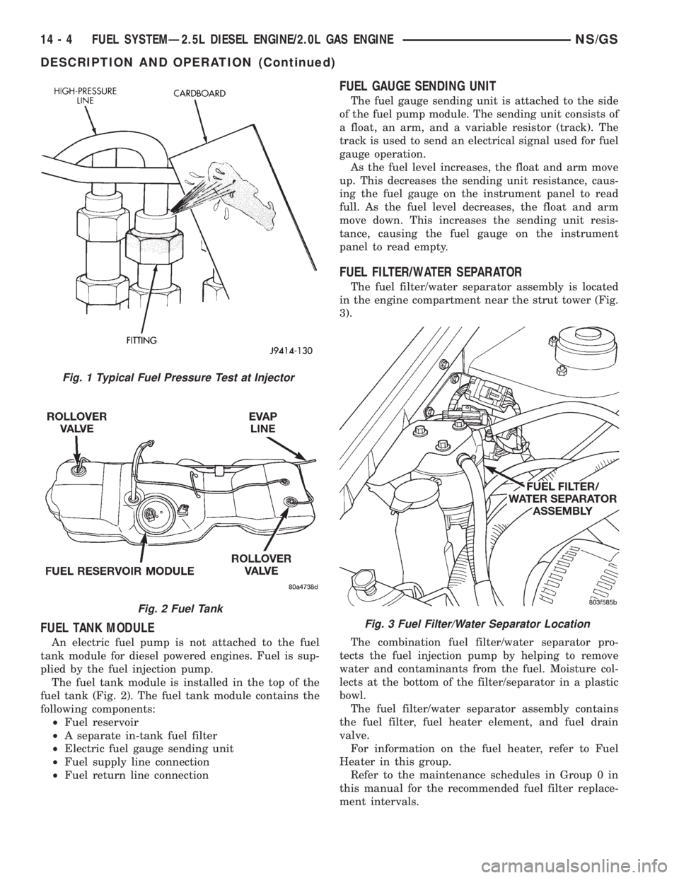
The fuel filter/water separator assembly is located
in the engine compartment near the strut tower (Fig.
3).
The combination fuel filter/water separator pro-
tects the fuel injection pump by helping to remove
water and contaminants from the fuel. Moisture col-
lects at the bottom of the filter/separator in a plastic
bowl.
The fuel filter/water separator assembly contains
the fuel filter, fuel heater element, and fuel drain
valve.
For information on the fuel heater, refer to Fuel
Heater in this group.
Refer to the maintenance schedules in Group 0 in
this manual for the recommended fuel filter replace-
ment intervals.
Fig. 1 Typical Fuel Pressure Test at Injector
Fig. 2 Fuel Tank
Fig. 3 Fuel Filter/Water Separator Location
14 - 4 FUEL SYSTEMÐ2.5L DIESEL ENGINE/2.0L GAS ENGINENS/GS
DESCRIPTION AND OPERATION (Continued)