oil capacity CHRYSLER VOYAGER 1996 User Guide
[x] Cancel search | Manufacturer: CHRYSLER, Model Year: 1996, Model line: VOYAGER, Model: CHRYSLER VOYAGER 1996Pages: 1938, PDF Size: 55.84 MB
Page 1218 of 1938
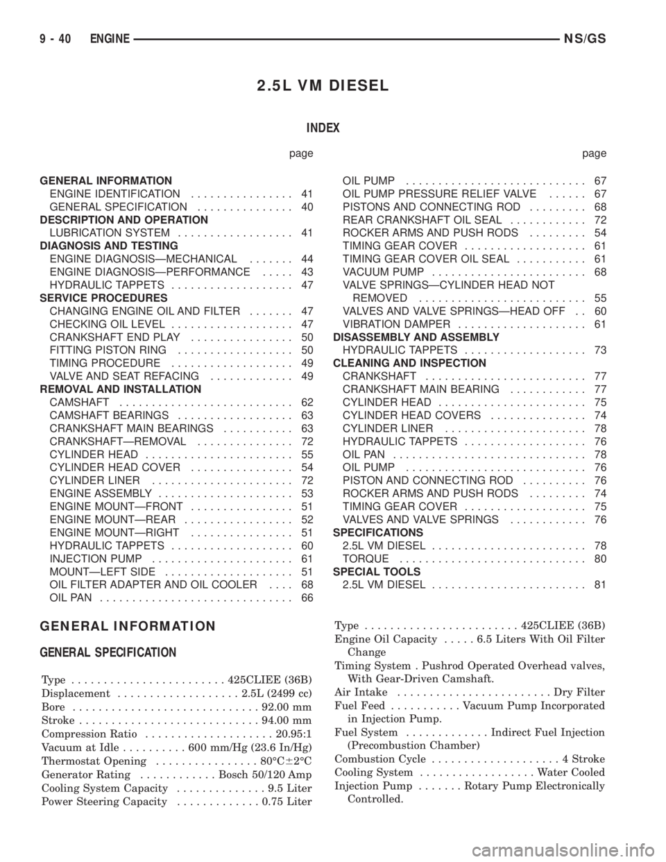
2.5L VM DIESEL
INDEX
page page
GENERAL INFORMATION
ENGINE IDENTIFICATION................ 41
GENERAL SPECIFICATION............... 40
DESCRIPTION AND OPERATION
LUBRICATION SYSTEM.................. 41
DIAGNOSIS AND TESTING
ENGINE DIAGNOSISÐMECHANICAL....... 44
ENGINE DIAGNOSISÐPERFORMANCE..... 43
HYDRAULIC TAPPETS................... 47
SERVICE PROCEDURES
CHANGING ENGINE OIL AND FILTER....... 47
CHECKING OIL LEVEL................... 47
CRANKSHAFT END PLAY................ 50
FITTING PISTON RING.................. 50
TIMING PROCEDURE................... 49
VALVE AND SEAT REFACING............. 49
REMOVAL AND INSTALLATION
CAMSHAFT........................... 62
CAMSHAFT BEARINGS.................. 63
CRANKSHAFT MAIN BEARINGS........... 63
CRANKSHAFTÐREMOVAL............... 72
CYLINDER HEAD....................... 55
CYLINDER HEAD COVER................ 54
CYLINDER LINER...................... 72
ENGINE ASSEMBLY..................... 53
ENGINE MOUNTÐFRONT................ 51
ENGINE MOUNTÐREAR................. 52
ENGINE MOUNTÐRIGHT................ 51
HYDRAULIC TAPPETS................... 60
INJECTION PUMP...................... 61
MOUNTÐLEFT SIDE.................... 51
OIL FILTER ADAPTER AND OIL COOLER.... 68
OILPAN .............................. 66OIL PUMP............................ 67
OIL PUMP PRESSURE RELIEF VALVE...... 67
PISTONS AND CONNECTING ROD......... 68
REAR CRANKSHAFT OIL SEAL............ 72
ROCKER ARMS AND PUSH RODS......... 54
TIMING GEAR COVER................... 61
TIMING GEAR COVER OIL SEAL........... 61
VACUUM PUMP........................ 68
VALVE SPRINGSÐCYLINDER HEAD NOT
REMOVED.......................... 55
VALVES AND VALVE SPRINGSÐHEAD OFF . . 60
VIBRATION DAMPER.................... 61
DISASSEMBLY AND ASSEMBLY
HYDRAULIC TAPPETS................... 73
CLEANING AND INSPECTION
CRANKSHAFT......................... 77
CRANKSHAFT MAIN BEARING............ 77
CYLINDER HEAD....................... 75
CYLINDER HEAD COVERS............... 74
CYLINDER LINER...................... 78
HYDRAULIC TAPPETS................... 76
OILPAN .............................. 78
OIL PUMP............................ 76
PISTON AND CONNECTING ROD.......... 76
ROCKER ARMS AND PUSH RODS......... 74
TIMING GEAR COVER................... 75
VALVES AND VALVE SPRINGS............ 76
SPECIFICATIONS
2.5L VM DIESEL........................ 78
TORQUE............................. 80
SPECIAL TOOLS
2.5L VM DIESEL........................ 81
GENERAL INFORMATION
GENERAL SPECIFICATION
Type ........................425CLIEE (36B)
Displacement...................2.5L (2499 cc)
Bore.............................92.00 mm
Stroke............................94.00 mm
Compression Ratio....................20.95:1
Vacuum at Idle..........600mm/Hg (23.6 In/Hg)
Thermostat Opening................80ÉC62ÉC
Generator Rating............Bosch 50/120 Amp
Cooling System Capacity..............9.5Liter
Power Steering Capacity.............0.75 LiterType ........................425CLIEE (36B)
Engine Oil Capacity.....6.5Liters With Oil Filter
Change
Timing System . Pushrod Operated Overhead valves,
With Gear-Driven Camshaft.
Air Intake........................DryFilter
Fuel Feed...........Vacuum Pump Incorporated
in Injection Pump.
Fuel System.............Indirect Fuel Injection
(Precombustion Chamber)
Combustion Cycle....................4Stroke
Cooling System..................Water Cooled
Injection Pump.......Rotary Pump Electronically
Controlled.
9 - 40 ENGINENS/GS
Page 1256 of 1938
(3) If internal diameter of original bearing is being
checked and figures are not within specifications,
new bearings must be used.
(4) Check crankshaft main bearing journals to
bearing clearances. Clearances of main bearings is
.03 to .088mm (.0011 to .0035 in.).
OIL PAN
Remove all gasket material from cylinder block. Be
careful not gouge pan sealing surface.
CYLINDER LINER
INSPECTION
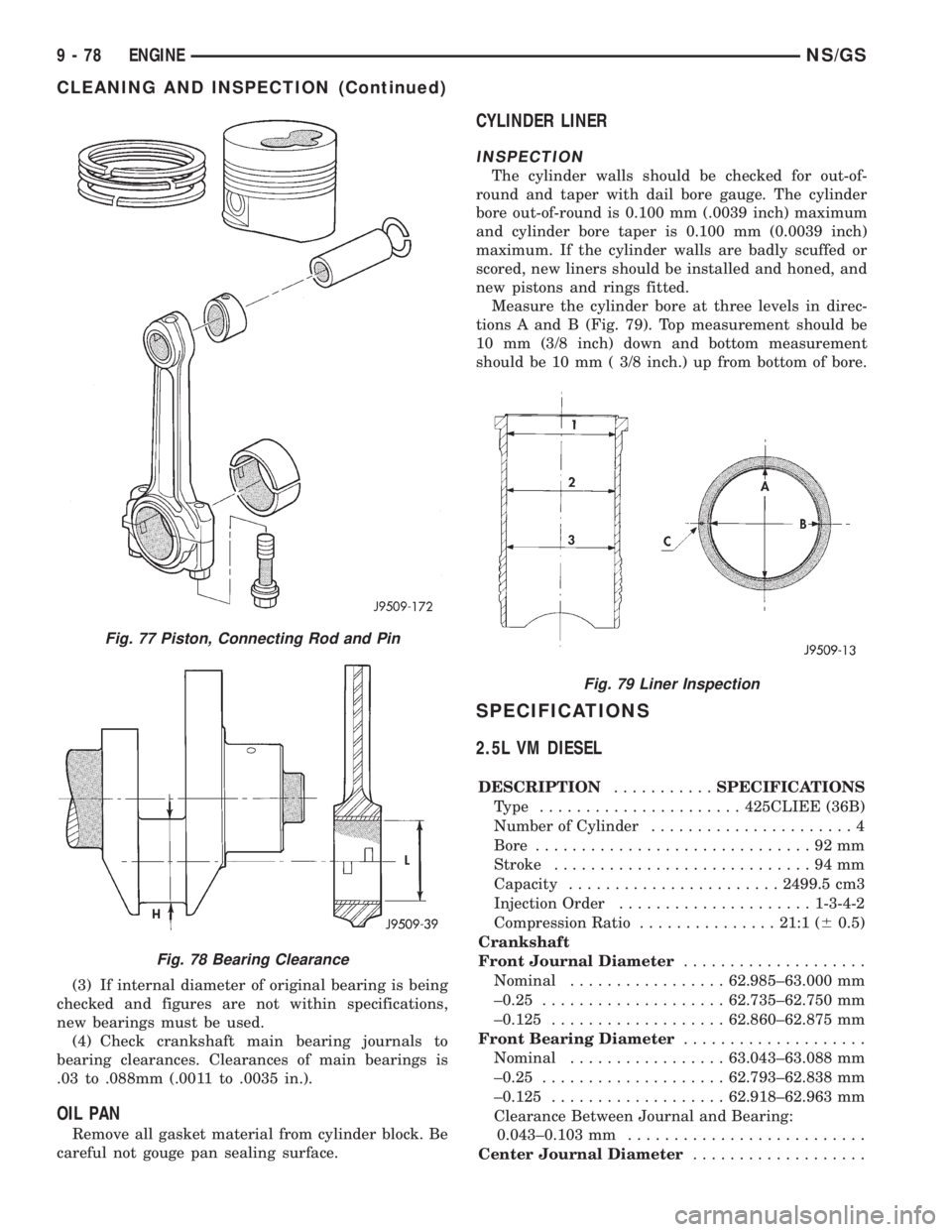
The cylinder walls should be checked for out-of-
round and taper with dail bore gauge. The cylinder
bore out-of-round is 0.100 mm (.0039 inch) maximum
and cylinder bore taper is 0.100 mm (0.0039 inch)
maximum. If the cylinder walls are badly scuffed or
scored, new liners should be installed and honed, and
new pistons and rings fitted.
Measure the cylinder bore at three levels in direc-
tions A and B (Fig. 79). Top measurement should be
10 mm (3/8 inch) down and bottom measurement
should be 10 mm ( 3/8 inch.) up from bottom of bore.
SPECIFICATIONS
2.5L VM DIESEL
DESCRIPTION...........SPECIFICATIONS
Type ......................425CLIEE (36B)
Number of Cylinder......................4
Bore..............................92mm
Stroke............................94mm
Capacity.......................2499.5 cm3
Injection Order.....................1-3-4-2
Compression Ratio...............21:1 (60.5)
Crankshaft
Front Journal Diameter....................
Nominal.................62.985±63.000 mm
±0.25....................62.735±62.750 mm
±0.125...................62.860±62.875 mm
Front Bearing Diameter....................
Nominal.................63.043±63.088 mm
±0.25....................62.793±62.838 mm
±0.125...................62.918±62.963 mm
Clearance Between Journal and Bearing:
0.043±0.103 mm..........................
Center Journal Diameter...................
Fig. 77 Piston, Connecting Rod and Pin
Fig. 78 Bearing Clearance
Fig. 79 Liner Inspection
9 - 78 ENGINENS/GS
CLEANING AND INSPECTION (Continued)
Page 1490 of 1938
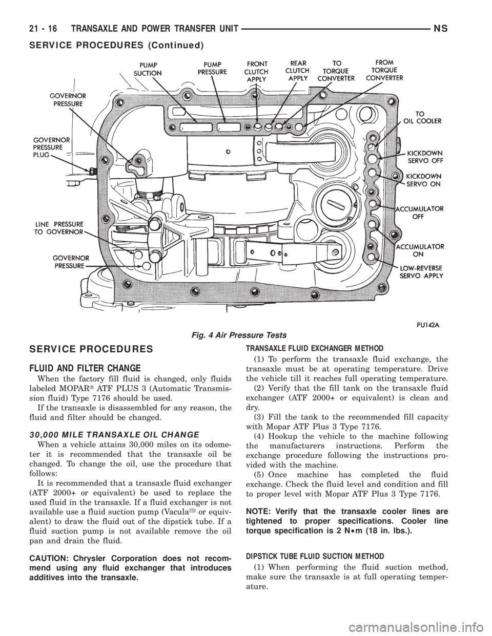
SERVICE PROCEDURES
FLUID AND FILTER CHANGE
When the factory fill fluid is changed, only fluids
labeled MOPARtATF PLUS 3 (Automatic Transmis-
sion fluid) Type 7176 should be used.
If the transaxle is disassembled for any reason, the
fluid and filter should be changed.
30,000 MILE TRANSAXLE OIL CHANGE
When a vehicle attains 30,000 miles on its odome-
ter it is recommended that the transaxle oil be
changed. To change the oil, use the procedure that
follows:
It is recommended that a transaxle fluid exchanger
(ATF 2000+ or equivalent) be used to replace the
used fluid in the transaxle. If a fluid exchanger is not
available use a fluid suction pump (Vaculayor equiv-
alent) to draw the fluid out of the dipstick tube. If a
fluid suction pump is not available remove the oil
pan and drain the fluid.
CAUTION: Chrysler Corporation does not recom-
mend using any fluid exchanger that introduces
additives into the transaxle.TRANSAXLE FLUID EXCHANGER METHOD
(1) To perform the transaxle fluid exchange, the
transaxle must be at operating temperature. Drive
the vehicle till it reaches full operating temperature.
(2) Verify that the fill tank on the transaxle fluid
exchanger (ATF 2000+ or equivalent) is clean and
dry.
(3) Fill the tank to the recommended fill capacity
with Mopar ATF Plus 3 Type 7176.
(4) Hookup the vehicle to the machine following
the manufacturers instructions. Perform the
exchange procedure following the instructions pro-
vided with the machine.
(5) Once machine has completed the fluid
exchange. Check the fluid level and condition and fill
to proper level with Mopar ATF Plus 3 Type 7176.
NOTE: Verify that the transaxle cooler lines are
tightened to proper specifications. Cooler line
torque specification is 2 N²m (18 in. lbs.).
DIPSTICK TUBE FLUID SUCTION METHOD
(1) When performing the fluid suction method,
make sure the transaxle is at full operating temper-
ature.
Fig. 4 Air Pressure Tests
21 - 16 TRANSAXLE AND POWER TRANSFER UNITNS
SERVICE PROCEDURES (Continued)
Page 1538 of 1938
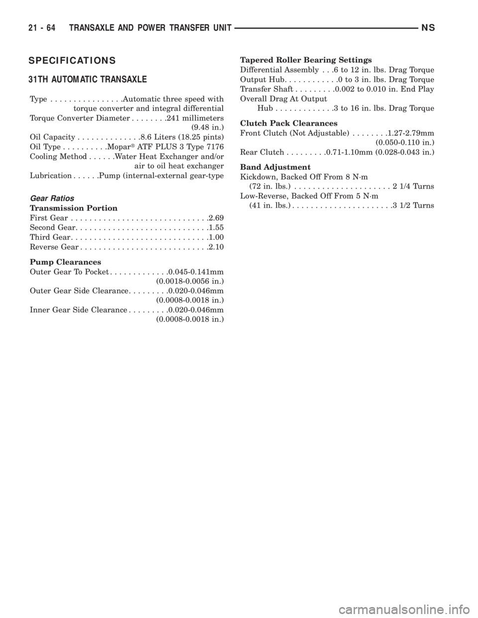
SPECIFICATIONS
31TH AUTOMATIC TRANSAXLE
Type ................Automatic three speed with
torque converter and integral differential
Torque Converter Diameter........241 millimeters
(9.48 in.)
Oil Capacity..............8.6 Liters (18.25 pints)
OilType..........MopartATF PLUS 3 Type 7176
Cooling Method......Water Heat Exchanger and/or
air to oil heat exchanger
Lubrication......Pump (internal-external gear-type
Gear Ratios
Transmission Portion
First Gear..............................2.69
Second Gear.............................1.55
Third Gear..............................1.00
Reverse Gear............................2.10
Pump Clearances
Outer Gear To Pocket.............0.045-0.141mm
(0.0018-0.0056 in.)
Outer Gear Side Clearance.........0.020-0.046mm
(0.0008-0.0018 in.)
Inner Gear Side Clearance.........0.020-0.046mm
(0.0008-0.0018 in.)Tapered Roller Bearing Settings
Differential Assembly . . .6 to 12 in. lbs. Drag Torque
Output Hub............0to3in.lbs. Drag Torque
Transfer Shaft.........0.002 to 0.010 in. End Play
Overall Drag At Output
Hub.............3to16in.lbs. Drag Torque
Clutch Pack Clearances
Front Clutch (Not Adjustable)........1.27-2.79mm
(0.050-0.110 in.)
Rear Clutch.........0.71-1.10mm (0.028-0.043 in.)
Band Adjustment
Kickdown, Backed Off From 8 N´m
(72 in. lbs.).....................21/4Turns
Low-Reverse, Backed Off From 5 N´m
(41 in. lbs.)......................31/2Turns
21 - 64 TRANSAXLE AND POWER TRANSFER UNITNS
Page 1547 of 1938
CAUTION: Some clutch packs appear similar, but
they are not the same. Do not interchange clutch
components, as they might fail.
HYDRAULICS
The hydraulics of the transaxle provide:
²Manual shift lever select function
²Main line pressure regulation
²Torque converter and cooler flow control
Oil flow to the friction elements is controlled
directly by four solenoid valves. The hydraulics also
include a unique logic- controlled solenoid torque con-
verter clutch control valve. This valve locks out the
1st gear reaction element with the application of 2nd,
direct, or overdrive gear elements. It also redirects
the 1st gear solenoid output so that it can control
torque converter clutch operation. To regain access to
1st gear, a sequence of commands must be used to
move the solenoid TCC control valve. This precludes
any application of the 1st gear reaction element with
other elements applied. It also allows one solenoid to
control two friction elements.
Small, high-rate accumulators are provided in each
controlled friction element circuit. These serve to
absorb the pressure responses, and allow the controls
to read and respond to changes that are occurring.
SOLENOIDS
The solenoid valves perform most control functions,
these valves must be extremely durable and tolerant
of dirt. For that reason hardened-steel poppet and
ball valves are used. These are free from any close
operating clearances. The solenoids operate the
valves directly without any intermediate element.
Direct operation means that these units must have
very high output. They must close against the size-
able flow areas and high line pressures. Fast
response is also required to meet the control require-
ments.
Two of the solenoids are normally-venting and two
are normally-applying; this was done to provide a
default mode of operation. With no electrical power,
the transmission provides 2nd gear in (OD), (3), or
(L) shift lever positions. All other transmission lever
positions will operate normally. The choice of 2nd
gear was made to provide adequate breakaway per-
formance while still accommodating highway speeds.
SENSORS
There are three pressure switches to identify sole-
noid application. There are two speed sensors to read
input (torque converter turbine) and output (parking
sprag) speeds. There is also a transmission range
sensor to indicate the manual shift lever position.
The pressure switches are incorporated in an assem-
bly with the solenoids. Engine speed, throttle posi-tion, temperature, etc., are also observed. Some of
these signals are read directly from the engine con-
trol sensors; others are read from a multiplex circuit
with the powertrain control module.
ELECTRONICS
The 41TE Transmission Control Module (TCM) is
located underhood in a potted, die-cast aluminum
housing. The module used is a new controller called
EATX III. The TCM has a sealed, 60-way connector.
ADAPTIVE CONTROLS
These controls function by reading the input and
output speeds over 140 times a second and respond-
ing to each new reading. This provides the precise
and sophisticated friction element control needed to
make smooth clutch-to-clutch shifts for all gear
changes. The use of overrunning clutches or other
shift quality aids are not required. As with most
automatic transaxles, all shifts involve releasing one
element and applying a different element. In simpli-
fied terms, the upshift logic allows the releasing ele-
ment to slip backwards slightly. This ensures that it
does not have excess capacity. The apply element is
filled until it begins to make the speed change to the
higher gear. The apply pressure is then controlled to
maintain the desired rate of speed change. This con-
tinues until the shift is made. The key to providing
excellent shift quality is precision. For example, the
release element for upshifts is allowed to slip back-
wards slightly. The amount of that slip is typically
less than a total of 20 degrees. To achieve that pre-
cision, the TCM learns the traits of the transaxle
that it is controlling. It learns the release rate of the
releasing element and the apply time of the applying
element. It also learns the rate at which the apply
element builds pressure sufficient to begin making
the speed change. This method achieves more preci-
sion than would be possible with exacting tolerances.
It can also adapt to any changes that occur with age
or environment.
For kickdown shifts, the control logic allows the
releasing element to slip. Then controls the rate at
which the input (and engine) accelerate. When the
lower gear speed is achieved, the releasing element
reapplies to maintain that speed until the apply ele-
ment is filled. This provides quick response since the
engine begins to accelerate immediately. This also
provides a smooth torque exchange since the release
element can control the rate of torque increase. This
control can make any powertrain feel more respon-
sive without increasing harshness.
Adaptive controls respond to input speed changes.
They compensate for changes in engine or friction
element torque and provide good, consistent shift
quality for the life of the transaxle.
NSTRANSAXLE AND POWER TRANSFER UNIT 21 - 73
DESCRIPTION AND OPERATION (Continued)
Page 1553 of 1938
If a problem arises with the shifter position indica-
tor, consult the following chart for diagnostic infor-
mation. If the malfunction cannot be corrected using
the chart, consult the proper diagnostic manual.
To replace the shifter position indicator, refer to
Group 8E, Instrument Panel And Gauges.SERVICE PROCEDURES
FLUID AND FILTER CHANGE
When the factory fill fluid is changed, only fluids
labeled MOPARtATF PLUS 3 (Automatic Transmis-
sion fluid) Type 7176 should be used.
If the transaxle is disassembled for any reason, the
fluid and filter should be changed.
30,000 MILE TRANSAXLE OIL CHANGE
When a vehicle attains 30,000 miles on its odome-
ter it is recommended that the transaxle oil be
changed. To change the oil, use the procedure that
follows:
It is recommended that a transaxle fluid exchanger
(ATF 2000+ or equivalent) be used to replace the
used fluid in the transaxle. If a fluid exchanger is not
available use a fluid suction pump (Vaculayor equiv-
alent) to draw the fluid out of the dipstick tube. If a
fluid suction pump is not available remove the oil
pan and drain the fluid.
CAUTION: Chrysler Corporation does not recom-
mend using any fluid exchanger that introduces
additives into the transaxle.
TRANSAXLE FLUID EXCHANGER METHOD
(1) To perform the transaxle fluid exchange, the
transaxle must be at operating temperature. Drive
the vehicle till it reaches full operating temperature.
(2) Verify that the fill tank on the transaxle fluid
exchanger (ATF 2000+ or equivalent) is clean and
dry.
(3) Fill the tank to the recommended fill capacity
with Mopar ATF Plus 3 Type 7176.
(4) Hookup the vehicle to the machine following
the manufacturers instructions. Perform the
exchange procedure following the instructions pro-
vided with the machine.
(5) Once machine has completed the fluid
exchange. Check the fluid level and condition and fill
to proper level with Mopar ATF Plus 3 Type 7176.
NOTE: Verify that the transaxle cooler lines are
tightened to proper specifications. Cooler line
torque specification is 2 N´m (18 in. lbs.).
CONDITION POSSIBLE CAUSE
ALL PRND3L DISPLAY
LIGHTS9ON9IN P&N
GEAR POSITIONS1.Check wiring and
connectors
2. Faulty trans. range
sensor
3. Faulty manual lever
ALL DISPLAY LIGHTS
9ON9IN ALL GEAR
POSITIONS1. Check wiring &
connectors
2. Faulty trans. range
sensor
3. Faulty manual lever
4. CCD communication
malfunction
5. Check oil level
ALL DISPLAY LIGHTS
9OFF91. Normal transient
condition between P&R
and R&N gear positions
2. Check shift lever
linkage
3. Body controller
malfunction
4. Check wiring and
connectors
5. Faulty cluster
ALL DISPLAY LIGHTS
9OFF9ACCOMPANIED
BY A9NO BUS9
MESSAGE1. CCD communication
malfunction
DISPLAY LIGHTS OUT
OF SEQUENCE WITH
SHIFT LEVER1. Check wiring and
connectors
2. Faulty trans. range
sensor
3. Faulty manual lever
4. CCD communication
malfunction
NSTRANSAXLE AND POWER TRANSFER UNIT 21 - 79
DIAGNOSIS AND TESTING (Continued)
Page 1632 of 1938
SPECIFICATIONS
41TE AUTOMATIC TRANSAXLE
Type..........................Fully adaptive,
electronically controlled,
four speed automatic with
torque converter
and integral differential
Torque Converter Diameter........241 millimeters
(9.48 in.)
Oil Capacity........................8.6 Liters
(18.25 pints)
OilType...........MopartATF PLUS 3Type 7176
Cooling Method...........Water Heat Exchanger
and/or air to oil
heat exchanger
Lubrication......Pump (internal-external gear-type
Gear Ratios
Transmission Portion
First Gear..............................2.84
Second Gear.............................1.57
Direct Gear.............................1.00
Overdrive Gear..........................0.69
Reverse Gear............................2.21
Overall Top Gear Ratio
3.8 Liter................................2.38
3.3 Liter................................2.49
2.4 Liter................................2.69
Pump Clearances
Outer Gear To Pocket.............0.045-0.141mm
(0.0018-0.0056 in.)
Outer Gear Side Clearance.........0.020-0.046mm
(0.0008-0.0018 in.)
Inner Gear Side Clearance.........0.020-0.046mm
(0.0008-0.0018 in.)
Tapered Roller Bearing Settings
Differential Assembly . . .5 to 18 in. lbs. Drag Torque
Output Hub............3to8in.lbs. Drag Torque
Transfer Shaft.........0.002 to 0.004 in. End Play
Overall Drag At Output Hub........3to16in.lbs.
Drag Torque
Clutch Pack Clearances
Low/Rev Clutch
(Select Reaction Plate)............0.89-1.04mm
(0.035-0.042 in.)
Two/Four Clutch
(No Selection)...................0.76-2.64mm
(0.030-0.104 in.)Reverse Clutch (Select Snap Ring).....0.76-1.24mm
(0.030-0.049 in.)
Overdrive Clutch
(No Selection)...................0.96-2.26mm
(0.038-0.089 in.)
Underdrive Clutch
Select Pressure Plate)............0.91-1.47mm
(0.036-0.058 in.)
Transmission End Play.............0.12-0.63mm
(0.005-0.025 in.)
41TE TORQUE SPECIFICATIONS
DESCRIPTION TORQUE
Cooler Line Fittings..........12N´m(105 in. lbs.)
Differential Cover............19N´m(165 in. lbs.)
Differential Ring Gear.........95N´m(70ft.lbs.)
Differential Bearing Ret........28N´m(21ft.lbs.)
Driveplate To Crank. Bolts......95N´m(70ft.lbs.)
Driveplate To Torque Conv.......75N´m(55ft.lbs.)
Eight Way Solenoid Conn........4N´m(35in.lbs.)
Extension Housing............28N´m(21ft.lbs.)
Input Speed Sensor............27N´m(20ft.lbs.)
L/R Clutch Retainer............5N´m(45in.lbs.)
Oil Pan To Trans. Case........19N´m(165 in. lbs.)
Output Gear Bolt...........271 N´m (200 ft. lbs.)
Output Gear Stirrup Ret........23N´m(17ft.lbs.)
Output Speed Sensor..........27N´m(20ft.lbs.)
Pressure Taps................5N´m(45in.lbs.)
Pump To Case Bolts...........27N´m(20ft.lbs.)
Reaction Shaft Bolts...........27N´m(20ft.lbs.)
Rear End Cover..............19N´m(14ft.lbs.)
Sixty-Way Connector...........4N´m(35in.lbs.)
Solenoid Assembly To Case.....12N´m(105 in. lbs.)
Transmission Range Sensor......5N´m(45in.lbs.)
Transfer Gear Nut..........271 N´m (200 ft. lbs.)
Transfer Plate To Case........12N´m(105 in. lbs.)
Valve Body To Case Bolts......12N´m(105 in. lbs.)
Valve Body Bolts..............5N´m(45in.lbs.)
Vent Assembly..............12N´m(105 in. lbs.)
21 - 158 TRANSAXLE AND POWER TRANSFER UNITNS
Page 1660 of 1938
²Improper operation
HARD SHIFTING
Hard shifting may be caused by a misadjusted
crossover cable. If hard shifting is accompanied by
gear clash, synchronizer clutch and stop rings or gear
teeth may be worn or damaged.
Misassembled synchronizer components also cause
shifting problems. Incorrectly installed synchronizer
sleeves, struts, or springs can cause shift problems.
NOISY OPERATION
Transaxle noise is most often a result of worn or
damaged components. Chipped, broken gear or syn-
chronizer teeth, and brinnelled, spalled bearings all
cause noise.
Abnormal wear and damage to the internal compo-
nents is frequently the end result of insufficient
lubricant.
SLIPS OUT OF GEAR
Transaxle disengagement may be caused by mis-
aligned or damaged shift components, or worn teeth
on the drive gears or synchronizer components. Incor-
rect assembly also causes gear disengagement.
LOW LUBRICANT LEVEL
Insufficient transaxle lubricant is usually the
result of leaks, or inaccurate fluid level check or refill
method. Leakage is evident by the presence of oil
around the leak point. If leakage is not evident, the
condition is probably the result of an underfill.
If air±powered lubrication equipment is used to fill
a transaxle, be sure the equipment is properly cali-
brated. Equipment out of calibration can lead to an
underfill condition.
The transaxle fill plug is located on the lower left
side of the transaxle end cover. With the vehicle at a
level position, remove the fill plug and check the
level of the lubricant. The lubricant level should be
within 3.175mm (1/8 inch) from the bottom of the fill
hole. If the lubricant level is low, fill the transaxle to
the bottom of the fill hole with SAE 5W-30 engine oil,
meeting SG and/or SG-CD qualifications, as the fac-
tory fill lubricant. SAE GL5 10W-40 engine oil is a
suitable service fill alternative.
CLUTCH PROBLEMS
Worn, damaged, or misaligned clutch components
can cause difficult shifting, gear clash, and noise.
A worn or damaged clutch disc, pressure plate, or
release bearing can cause hard shifting and gear
clash.
SERVICE PROCEDURES
FLUID DRAIN AND FILL
TRANSAXLE FLUID DRAIN
(1) Hoist vehicle.
(2) Install a drain pan underneath the transaxle
drain plug.
(3) Remove the transaxle drain plug. The drain
plug is located on the bottom of the transaxle hous-
ing.
(4) Let fluid drain out till there is just an occa-
sional drip.
(5) Reinstall drain plug. Tighten drain plug to 28
N´m (250 in. lbs.)
TRANSAXLE FLUID FILL
NOTE: All A-598 transaxles are equipped with a fill
plug. The fill plug is located on the end cover side
of the transaxle.
(1) Remove transaxle fill plug
The fluid level should be within 3.175mm (1/8
inch) from the bottom of the transaxle fill hole (vehi-
cle must be level when checking).
(2) Fill transaxle to proper level with SAE 5W-30
engine oil, meeting SG and/or SG-CD qualifications.
G5 SAE 10W-40 engine oil is a suitable service fill
alternative. Dry fill lubricant capacity is approxi-
mately 1.9-2.2 liters (4.0-4.6 pints)..
(3) Wipe the outside of the transaxle if any lubri-
cant spills.
(4) Reinstall transaxle fill plug.
FLUID DRAIN AND FILLÐRHD VEHICLES
TRANSAXLE FLUID DRAIN
(1) Hoist vehicle.
(2) Install a drain pan underneath the transaxle
drain plug.
(3) Remove the transaxle drain plug. The drain
plug is located on the bottom of the transaxle hous-
ing (Fig. 5).
(4) Let fluid drain out till there is just an occa-
sional drip.
(5) Reinstall drain plug. Tighten drain plug to 28
N´m (250 in. lbs.)
TRANSAXLE FLUID FILL
NOTE: All A-558 transaxles are equipped with a fill
plug. The fill plug is located on the end cover side
of the transaxle.
(1) Remove transaxle fill plug
21 - 4 A±598 MANUAL TRANSAXLENS/GS
DIAGNOSIS AND TESTING (Continued)
Page 1661 of 1938
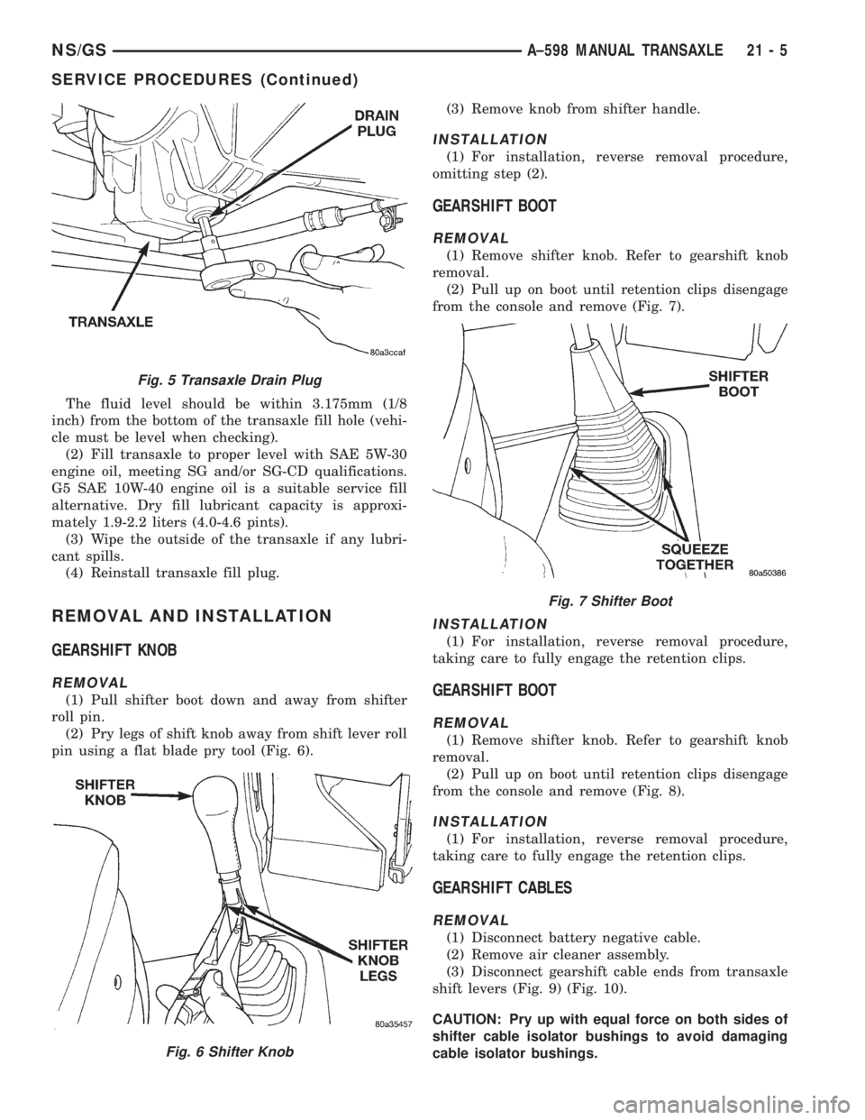
The fluid level should be within 3.175mm (1/8
inch) from the bottom of the transaxle fill hole (vehi-
cle must be level when checking).
(2) Fill transaxle to proper level with SAE 5W-30
engine oil, meeting SG and/or SG-CD qualifications.
G5 SAE 10W-40 engine oil is a suitable service fill
alternative. Dry fill lubricant capacity is approxi-
mately 1.9-2.2 liters (4.0-4.6 pints).
(3) Wipe the outside of the transaxle if any lubri-
cant spills.
(4) Reinstall transaxle fill plug.
REMOVAL AND INSTALLATION
GEARSHIFT KNOB
REMOVAL
(1) Pull shifter boot down and away from shifter
roll pin.
(2) Pry legs of shift knob away from shift lever roll
pin using a flat blade pry tool (Fig. 6).(3) Remove knob from shifter handle.
INSTALLATION
(1) For installation, reverse removal procedure,
omitting step (2).
GEARSHIFT BOOT
REMOVAL
(1) Remove shifter knob. Refer to gearshift knob
removal.
(2) Pull up on boot until retention clips disengage
from the console and remove (Fig. 7).
INSTALLATION
(1) For installation, reverse removal procedure,
taking care to fully engage the retention clips.
GEARSHIFT BOOT
REMOVAL
(1) Remove shifter knob. Refer to gearshift knob
removal.
(2) Pull up on boot until retention clips disengage
from the console and remove (Fig. 8).
INSTALLATION
(1) For installation, reverse removal procedure,
taking care to fully engage the retention clips.
GEARSHIFT CABLES
REMOVAL
(1) Disconnect battery negative cable.
(2) Remove air cleaner assembly.
(3) Disconnect gearshift cable ends from transaxle
shift levers (Fig. 9) (Fig. 10).
CAUTION: Pry up with equal force on both sides of
shifter cable isolator bushings to avoid damaging
cable isolator bushings.
Fig. 5 Transaxle Drain Plug
Fig. 6 Shifter Knob
Fig. 7 Shifter Boot
NS/GSA±598 MANUAL TRANSAXLE 21 - 5
SERVICE PROCEDURES (Continued)
Page 1819 of 1938
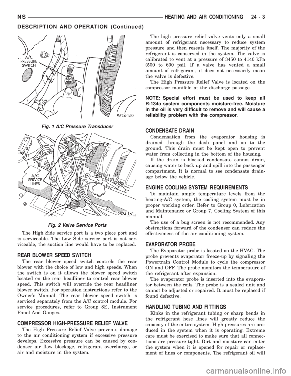
The High Side service port is a two piece port and
is serviceable. The Low Side service port is not ser-
viceable, the suction line would have to be replaced.
REAR BLOWER SPEED SWITCH
The rear blower speed switch controls the rear
blower with the choice of low and high speeds. When
the switch is on it allows the blower speed switch
located on the rear headliner to control rear blower
speed. This switch will override the rear headliner
blower switch. For operation instructions refer to the
Owner's Manual. The rear blower speed switch is
serviced separately from the A/C control module. For
service procedures, refer to Group 8E, Instrument
Panel And Gauges.
COMPRESSOR HIGH-PRESSURE RELIEF VALVE
The High Pressure Relief Valve prevents damage
to the air conditioning system if excessive pressure
develops. Excessive pressure can be caused by con-
denser air flow blockage, refrigerant overcharge, or
air and moisture in the system.The high pressure relief valve vents only a small
amount of refrigerant necessary to reduce system
pressure and then reseats itself. The majority of the
refrigerant is conserved in the system. The valve is
calibrated to vent at a pressure of 3450 to 4140 kPa
(500 to 600 psi). If a valve has vented a small
amount of refrigerant, it does not necessarily mean
the valve is defective.
The High Pressure Relief Valve is located on the
compressor manifold at the discharge passage.
NOTE: Special effort must be used to keep all
R-134a system components moisture-free. Moisture
in the oil is very difficult to remove and will cause a
reliability problem with the compressor.
CONDENSATE DRAIN
Condensation from the evaporator housing is
drained through the dash panel and on to the
ground. This drain must be kept open to prevent
water from collecting in the bottom of the housing.
If the drain is blocked condensate cannot drain,
causing water to back up and spill into the passenger
compartment. It is normal to see condensate drain-
age below the vehicle.
ENGINE COOLING SYSTEM REQUIREMENTS
To maintain ample temperature levels from the
heating-A/C system, the cooling system must be in
proper working order. Refer to Group 0, Lubrication
and Maintenance or Group 7, Cooling System of this
manual.
The use of a bug screen is not recommended. Any
obstructions forward of the condenser can reduce the
effectiveness of the air conditioning system.
EVAPORATOR PROBE
The Evaporator probe is located on the HVAC. The
probe prevents evaporator freeze-up by signaling the
Powertrain Control Module to cycle the compressor
ON and OFF. The probe monitors the temperature of
the refrigerant after expansion.
The evaporator probe is inserted into the evapora-
tor between the coils. The probe is a sealed unit and
cannot be adjusted or repaired. It must be replaced if
found defective.
HANDLING TUBING AND FITTINGS
Kinks in the refrigerant tubing or sharp bends in
the refrigerant hose lines will greatly reduce the
capacity of the entire system. High pressures are pro-
duced in the system when it is operating. Extreme
care must be exercised to make sure that all connec-
tions are pressure tight. Dirt and moisture can enter
the system when it is opened for repair or replace-
ment of lines or components. The refrigerant oil will
Fig. 1 A/C Pressure Transducer
Fig. 2 Valve Service Ports
NSHEATING AND AIR CONDITIONING 24 - 3
DESCRIPTION AND OPERATION (Continued)