display CHRYSLER VOYAGER 1996 Owner's Manual
[x] Cancel search | Manufacturer: CHRYSLER, Model Year: 1996, Model line: VOYAGER, Model: CHRYSLER VOYAGER 1996Pages: 1938, PDF Size: 55.84 MB
Page 350 of 1938
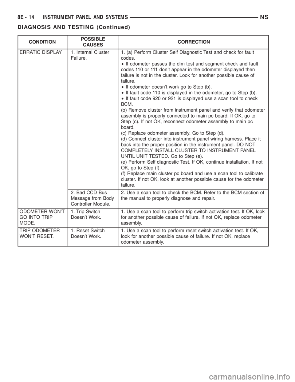
CONDITIONPOSSIBLE
CAUSESCORRECTION
ERRATIC DISPLAY 1. Internal Cluster
Failure.1. (a) Perform Cluster Self Diagnostic Test and check for fault
codes.
²If odometer passes the dim test and segment check and fault
codes 110 or 111 don't appear in the odometer displayed then
failure is not in the cluster. Look for another possible cause of
failure.
²If odometer doesn't work go to Step (b).
²If fault code 110 is displayed in the odometer, go to Step (b).
²If fault code 920 or 921 is displayed use a scan tool to check
BCM.
(b) Remove cluster from instrument panel and verify that odometer
assembly is properly connected to main pc board. If OK, go to
Step (c). If not OK, reconnect odometer assembly to main pc
board.
(c) Replace odometer assembly. Go to Step (d).
(d) Connect cluster into instrument panel wiring harness. Place it
back into the proper position in the instrument panel. DO NOT
COMPLETELY INSTALL CLUSTER TO INSTRUMENT PANEL
UNTIL UNIT TESTED. Go to Step (e).
(e) Perform Self diagnostic Test. If OK, continue installation. If not
OK, go to Step (f).
(f) Replace main cluster pc board and use a scan tool to calibrate
cluster. If not OK, look at another possible cause for the odometer
failure.
2. Bad CCD Bus
Message from Body
Controller Module.2. Use a scan tool to check the BCM. Refer to the BCM section of
the manual to properly diagnose and repair.
ODOMETER WON'T
GO INTO TRIP
MODE.1. Trip Switch
Doesn't Work.1. Use a scan tool to perform trip switch activation test. If OK, look
for another possible cause of failure. If not OK, replace odometer
assembly.
TRIP ODOMETER
WON'T RESET.1. Reset Switch
Doesn't Work.1. Use a scan tool to perform reset switch activation test. If OK,
look for another possible cause of failure. If not OK, replace
odometer assembly.
8E - 14 INSTRUMENT PANEL AND SYSTEMSNS
DIAGNOSIS AND TESTING (Continued)
Page 351 of 1938
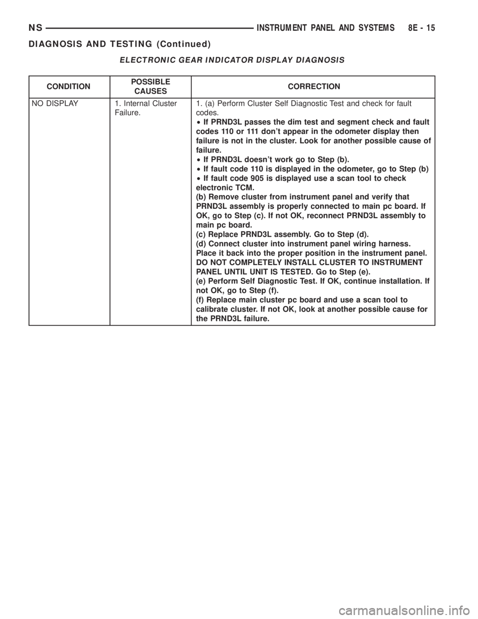
ELECTRONIC GEAR INDICATOR DISPLAY DIAGNOSIS
CONDITIONPOSSIBLE
CAUSESCORRECTION
NO DISPLAY 1. Internal Cluster
Failure.1. (a) Perform Cluster Self Diagnostic Test and check for fault
codes.
²If PRND3L passes the dim test and segment check and fault
codes 110 or 111 don't appear in the odometer display then
failure is not in the cluster. Look for another possible cause of
failure.
²If PRND3L doesn't work go to Step (b).
²If fault code 110 is displayed in the odometer, go to Step (b)
²If fault code 905 is displayed use a scan tool to check
electronic TCM.
(b) Remove cluster from instrument panel and verify that
PRND3L assembly is properly connected to main pc board. If
OK, go to Step (c). If not OK, reconnect PRND3L assembly to
main pc board.
(c) Replace PRND3L assembly. Go to Step (d).
(d) Connect cluster into instrument panel wiring harness.
Place it back into the proper position in the instrument panel.
DO NOT COMPLETELY INSTALL CLUSTER TO INSTRUMENT
PANEL UNTIL UNIT IS TESTED. Go to Step (e).
(e) Perform Self Diagnostic Test. If OK, continue installation. If
not OK, go to Step (f).
(f) Replace main cluster pc board and use a scan tool to
calibrate cluster. If not OK, look at another possible cause for
the PRND3L failure.
NSINSTRUMENT PANEL AND SYSTEMS 8E - 15
DIAGNOSIS AND TESTING (Continued)
Page 352 of 1938
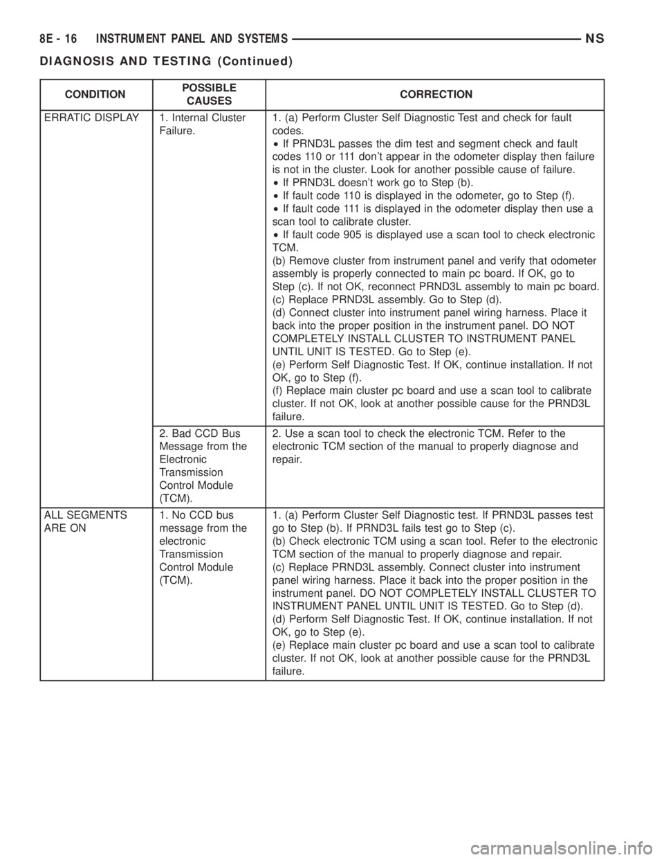
CONDITIONPOSSIBLE
CAUSESCORRECTION
ERRATIC DISPLAY 1. Internal Cluster
Failure.1. (a) Perform Cluster Self Diagnostic Test and check for fault
codes.
²If PRND3L passes the dim test and segment check and fault
codes 110 or 111 don't appear in the odometer display then failure
is not in the cluster. Look for another possible cause of failure.
²If PRND3L doesn't work go to Step (b).
²If fault code 110 is displayed in the odometer, go to Step (f).
²If fault code 111 is displayed in the odometer display then use a
scan tool to calibrate cluster.
²If fault code 905 is displayed use a scan tool to check electronic
TCM.
(b) Remove cluster from instrument panel and verify that odometer
assembly is properly connected to main pc board. If OK, go to
Step (c). If not OK, reconnect PRND3L assembly to main pc board.
(c) Replace PRND3L assembly. Go to Step (d).
(d) Connect cluster into instrument panel wiring harness. Place it
back into the proper position in the instrument panel. DO NOT
COMPLETELY INSTALL CLUSTER TO INSTRUMENT PANEL
UNTIL UNIT IS TESTED. Go to Step (e).
(e) Perform Self Diagnostic Test. If OK, continue installation. If not
OK, go to Step (f).
(f) Replace main cluster pc board and use a scan tool to calibrate
cluster. If not OK, look at another possible cause for the PRND3L
failure.
2. Bad CCD Bus
Message from the
Electronic
Transmission
Control Module
(TCM).2. Use a scan tool to check the electronic TCM. Refer to the
electronic TCM section of the manual to properly diagnose and
repair.
ALL SEGMENTS
ARE ON1. No CCD bus
message from the
electronic
Transmission
Control Module
(TCM).1. (a) Perform Cluster Self Diagnostic test. If PRND3L passes test
go to Step (b). If PRND3L fails test go to Step (c).
(b) Check electronic TCM using a scan tool. Refer to the electronic
TCM section of the manual to properly diagnose and repair.
(c) Replace PRND3L assembly. Connect cluster into instrument
panel wiring harness. Place it back into the proper position in the
instrument panel. DO NOT COMPLETELY INSTALL CLUSTER TO
INSTRUMENT PANEL UNTIL UNIT IS TESTED. Go to Step (d).
(d) Perform Self Diagnostic Test. If OK, continue installation. If not
OK, go to Step (e).
(e) Replace main cluster pc board and use a scan tool to calibrate
cluster. If not OK, look at another possible cause for the PRND3L
failure.
8E - 16 INSTRUMENT PANEL AND SYSTEMSNS
DIAGNOSIS AND TESTING (Continued)
Page 374 of 1938
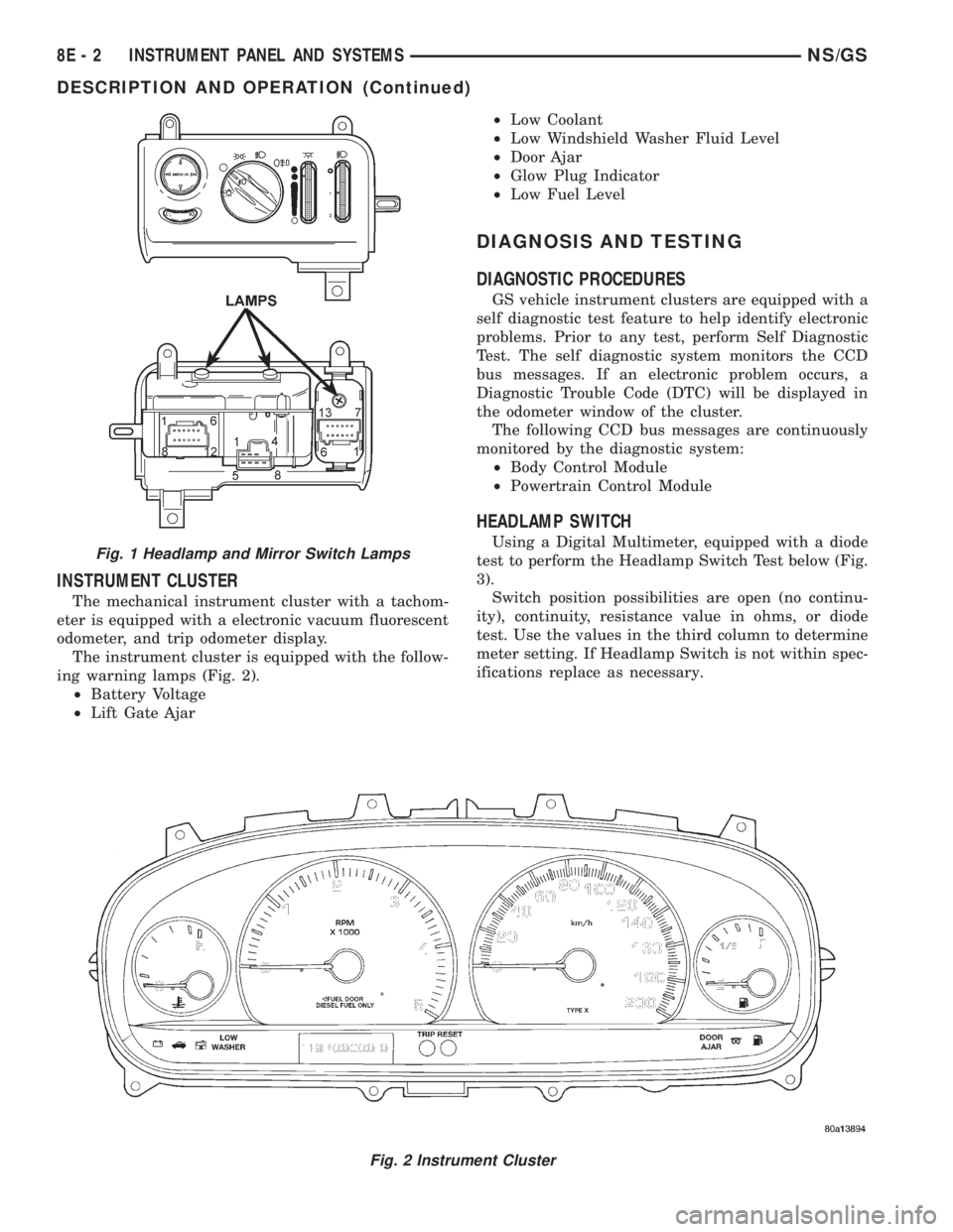
INSTRUMENT CLUSTER
The mechanical instrument cluster with a tachom-
eter is equipped with a electronic vacuum fluorescent
odometer, and trip odometer display.
The instrument cluster is equipped with the follow-
ing warning lamps (Fig. 2).
²Battery Voltage
²Lift Gate Ajar²Low Coolant
²Low Windshield Washer Fluid Level
²Door Ajar
²Glow Plug Indicator
²Low Fuel Level
DIAGNOSIS AND TESTING
DIAGNOSTIC PROCEDURES
GS vehicle instrument clusters are equipped with a
self diagnostic test feature to help identify electronic
problems. Prior to any test, perform Self Diagnostic
Test. The self diagnostic system monitors the CCD
bus messages. If an electronic problem occurs, a
Diagnostic Trouble Code (DTC) will be displayed in
the odometer window of the cluster.
The following CCD bus messages are continuously
monitored by the diagnostic system:
²Body Control Module
²Powertrain Control Module
HEADLAMP SWITCH
Using a Digital Multimeter, equipped with a diode
test to perform the Headlamp Switch Test below (Fig.
3).
Switch position possibilities are open (no continu-
ity), continuity, resistance value in ohms, or diode
test. Use the values in the third column to determine
meter setting. If Headlamp Switch is not within spec-
ifications replace as necessary.
Fig. 2 Instrument Cluster
Fig. 1 Headlamp and Mirror Switch Lamps
8E - 2 INSTRUMENT PANEL AND SYSTEMSNS/GS
DESCRIPTION AND OPERATION (Continued)
Page 375 of 1938
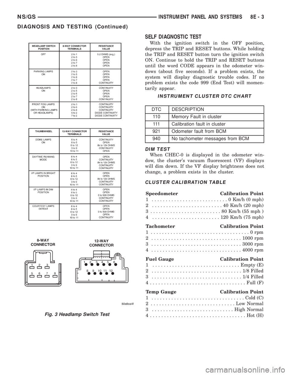
SELF DIAGNOSTIC TEST
With the ignition switch in the OFF position,
depress the TRIP and RESET buttons. While holding
the TRIP and RESET button turn the ignition switch
ON. Continue to hold the TRIP and RESET buttons
until the word CODE appears in the odometer win-
dows (about five seconds). If a problem exists, the
system will display diagnostic trouble codes. If no
problem exists the code 999 (End Test) will momen-
tarily appear.
DIM TEST
When CHEC-0 is displayed in the odometer win-
dow, the cluster's vacuum fluorescent (VF) displays
will dim down. If the VF display brightness does not
change, a problem exists in the cluster.
CLUSTER CALIBRATION TABLE
Speedometer Calibration Point
1 ...........................0Km/h (0 mph)
2 .........................40Km/h (20 mph)
3 .........................80Km/h (55 mph )
4 ........................120Km/h (75 mph)
Tachometer Calibration Point
1 ...................................0rpm
2 ................................1000 rpm
3 ................................3000 rpm
4 ................................4000 rpm
Fuel Gauge Calibration Point
1 ...............................Empty (E)
2 ................................1/8Filled
3 ................................1/4Filled
4..................................Full (F)
Temp Gauge Calibration Point
1 .................................Cold (C)
2 ..............................LowNormal
3 .............................High Normal
4 ..................................Hot(H)
Fig. 3 Headlamp Switch Test
INSTRUMENT CLUSTER DTC CHART
DTC DESCRIPTION
110 Memory Fault in cluster
111 Calibration fault in cluster
921 Odometer fault from BCM
940 No tachometer messages from BCM
NS/GSINSTRUMENT PANEL AND SYSTEMS 8E - 3
DIAGNOSIS AND TESTING (Continued)
Page 376 of 1938
CALIBRATION TEST
When CHEC-1 is displayed in the odometer win-
dow, each of the cluster's gauge pointers will move
sequentially through each calibration point. The Cal-
ibration Table contains the proper calibration points
for each gauge. If the gauge pointers are not cali-
brated, a problem exists in the cluster. If any gauge
is out of calibration it will have to be calibrated using
a scan tool (DRB III). Refer to the proper Body Diag-
nostic Procedure Manual for calibration procedures.
ODOMETER SEGMENT TEST
When CHEC-2 is displayed in the odometer win-
dow, each digit of the odometer will illuminate
sequentially. If a segment in the odometer does not
illuminate normally, a problem exists in the display.
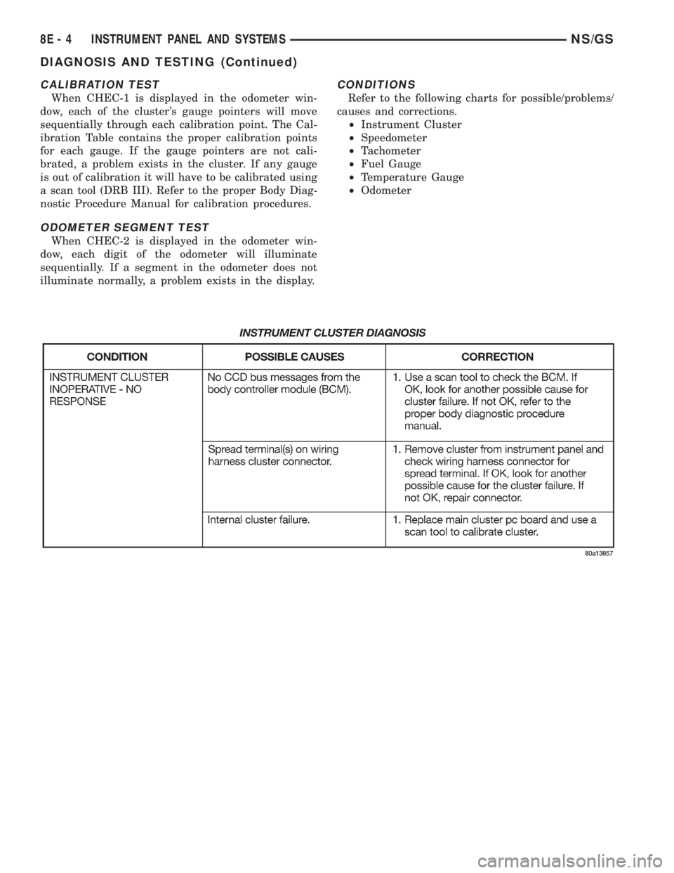
CONDITIONS
Refer to the following charts for possible/problems/
causes and corrections.
²Instrument Cluster
²Speedometer
²Tachometer
²Fuel Gauge
²Temperature Gauge
²Odometer
8E - 4 INSTRUMENT PANEL AND SYSTEMSNS/GS
DIAGNOSIS AND TESTING (Continued)
Page 407 of 1938
CONDITION POSSIBLE CAUSE CORRECTION
NO AUDIO. 1. FUSE FAULTY.
2. RADIO CONNECTOR
FAULTY.
3. WIRING FAULTY.
4. GROUND FAULTY.
5. RADIO FAULTY.
6. SPEAKERS FAULTY.1. CHECK RADIO FUSES IN FUSEBLOCK MODULE.
REPLACE FUSES, IF REQUIRED.
2. CHECK FOR LOOSE OR CORRODED RADIO
CONNECTOR. REPAIR, IF REQUIRED.
3. CHECK FOR BATTERY VOLTAGE AT RADIO
CONNECTOR. REPAIR WIRING, IF REQUIRED.
4. CHECK FOR CONTINUITY BETWEEN RADIO CHASSIS
AND A KNOWN GOOD GROUND. THERE SHOULD BE
CONTINUITY. REPAIR GROUND, IF REQUIRED.
5. EXCHANGE OR REPLACE RADIO, IF REQUIRED.
6. SEE SPEAKER DIAGNOSIS, IN THIS GROUP.
NO DISPLAY. 1. FUSE FAULTY.
2. RADIO CONNECTOR
FAULTY.
3. WIRING FAULTY.
4. GROUND FAULTY.
5. RADIO FAULTY.1. CHECK RADIO FUSES IN FUSEBLOCK MODULE.
REPLACE FUSES, IF REQUIRED.
2. CHECK FOR LOOSE OR CORRODED RADIO
CONNECTOR. REPAIR, IF REQUIRED.
3. CHECK FOR BATTERY VOLTAGE AT RADIO
CONNECTOR. REPAIR WIRING, IF REQUIRED.
4. CHECK FOR CONTINUITY BETWEEN RADIO CHASSIS
AND A KNOWN GOOD GROUND. THERE SHOULD BE
CONTINUITY. REPAIR GROUND, IF REQUIRED.
5. EXCHANGE OR REPLACE RADIO, IF REQUIRED.
NO MEMORY. 1. FUSE FAULTY.
2. RADIO CONNECTOR
FAULTY.
3. WIRING FAULTY.
4. GROUND FAULTY.
5. RADIO FAULTY.1. CHECK IGNITION-OFF DRAW FUSE. REPLACE FUSE,
IF REQUIRED.
2. CHECK FOR LOOSE OR CORRODED RADIO
CONNECTOR. REPAIR, IF REQUIRED.
3. CHECK FOR BATTERY VOLTAGE AT RADIO
CONNECTOR. REPAIR WIRING, IF REQUIRED.
4. CHECK FOR CONTINUITY BETWEEN RADIO CHASSIS
AND A KNOWN GOOD GROUND. THERE SHOULD BE
CONTINUITY. REPAIR GROUND, IF REQUIRED.
5. EXCHANGE OR REPLACE RADIO, IF REQUIRED.
POOR RADIO
RECEPTION.1. ANTENNA FAULTY.
2. GROUND FAULTY.
3. RADIO FAULTY.1. SEE ANTENNA DIAGNOSIS, IN THIS GROUP. REPAIR
OR REPLACE ANTENNA, IF REQUIRED.
2. CHECK FOR CONTINUITY BETWEEN RADIO CHASSIS
AND A KNOWN GOOD GROUND. THERE SHOULD BE
CONTINUITY. REPAIR GROUND, IF REQUIRED..
3. EXCHANGE OR REPLACE RADIO, IF REQUIRED.
NO/POOR TAPE
OPERATION.1. FAULTY TAPE.
2. FOREIGN OBJECTS
BEHIND TAPE DOOR.
3. DIRTY CASSETTE TAPE
HEAD.
4. FAULTY TAPE DECK.1. INSERT KNOWN GOOD TAPE AND TEST OPERATION.
2. REMOVE FOREIGN OBJECTS AND TEST OPERATION.
3. CLEAN HEAD WITH MOPAR CASSETTE HEAD
CLEANER.
4. EXCHANGE OR REPLACE RADIO, IF REQUIRED.
NO COMPACT
DISC
OPERATION1. FAULTY CD.
2. FOREIGN MATERIAL ON
CD.
3. CONDENSATION ON CD
OR OPTICS.
4. FAULTY CD PLAYER.1. INSERT KNOWN GOOD CD AND TEST OPERATION.
2. CLEAN CD AND TEST OPERATION.
3. ALLOW TEMPERATURE OF VEHICLE INTERIOR TO
STABILIZE AND TEST OPERATION.
4. EXCHANGE OR REPLACE RADIO, IF REQUIRED.
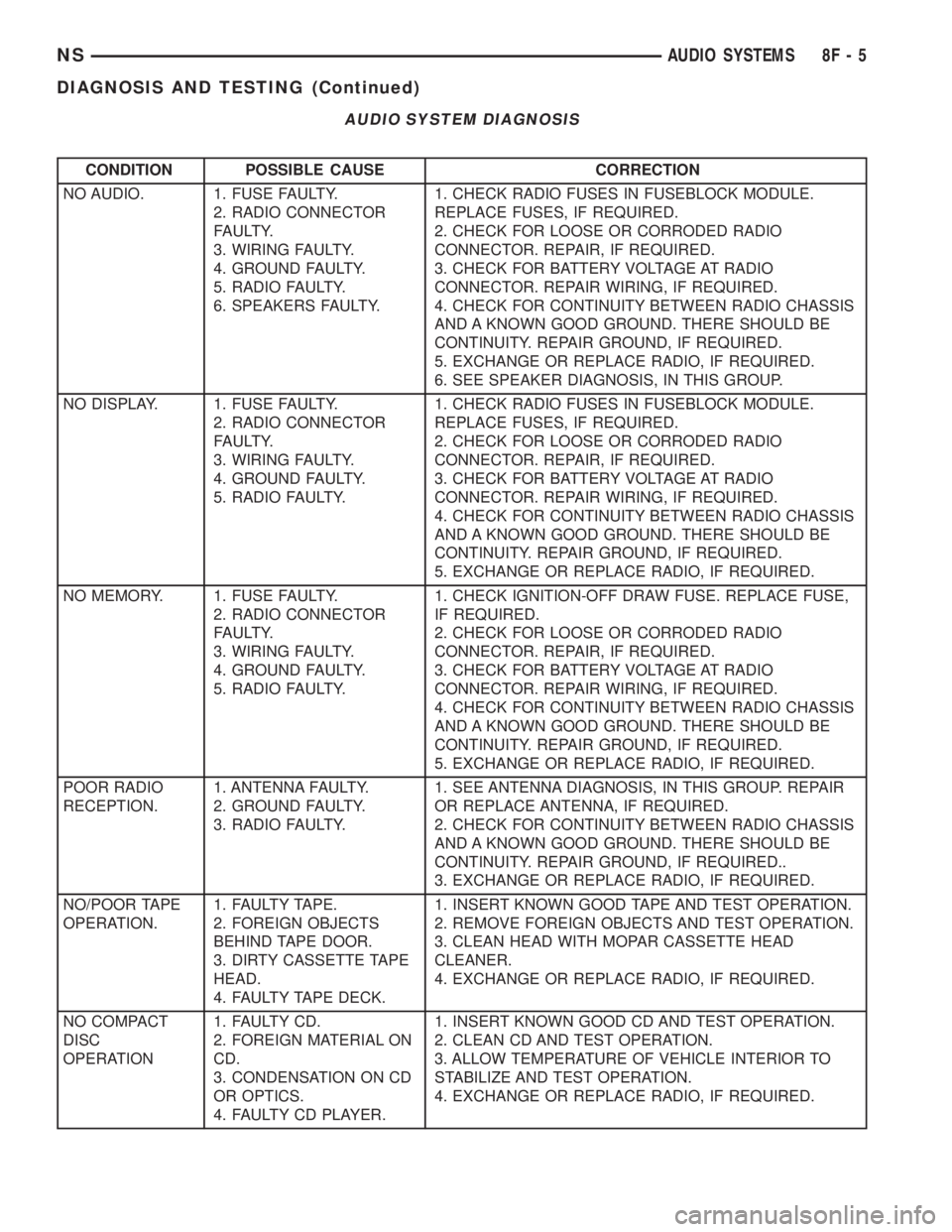
AUDIO SYSTEM DIAGNOSIS
NSAUDIO SYSTEMS 8F - 5
DIAGNOSIS AND TESTING (Continued)
Page 420 of 1938

Refer to Group 25, for further information and use-
age of the DRB scan tool and a more complete list of
Diagnostic Trouble Code.
SPEED CONTROL SLOWS DOWN BY ITSELF
Test vehicle speed sensor, refer to group 8E. If sen-
sor fails replace sensor, if it passes perform the fol-
lowing test:
(1) Perform the speed control switch test on the
DECEL switch, if it fails replace switch.
(2) If the switch passes, conduct the vacuum sup-
ply test.
(3) If it passes, conduct the servo vacuum test. If it
fails replace servo.
(4) If continuity, replace the PCM.
SPEED CONTROL ELECTRICAL TEST
Electronic speed control systems may be tested
using two different methods. One involves use of a
DRB. If this test method is desired, refer to the Pow-
ertrain Diagnostic Test Procedures for charging and
speed control system manual.The other test method uses a volt/ohm meter. The
volt/ohm meter method is described in the following
tests.
If any information is needed concerning wiring,
refer to Group 8W, Wiring Diagrams (Fig. 2).
CAUTION: When test probing for voltage or conti-
nuity at electrical connectors, care must be taken
not to damage connector, terminals, or seals. If
these components are damaged, intermittent or
complete system failure may occur.
When electrical connections are removed, corrosion
should be removed from electrical terminals and a
light coating of Mopar Multi-Purpose Grease, or
equivalent, applied. Inspect connectors for damage
terminals.
A poor connection can cause a complete or inter-
mittent malfunction and is also the only connection
in the circuit, that can not be tested. For this reason,
a loose connection may be misdiagnosed as a compo-
nent malfunction.
SPEED CONTROL DIAGNOSTIC TROUBLE CODES
Hex Code DRB Scan Tool Display Description of Diagnostic Trouble
Code
23 No Vehicle Speed Sensor Signal No vehicle distance (speed) sensor
signal detected during road load
conditions.
OF Speed Control Solenoid Circuits An open or shorted condition
detected in the Speed Control
vacuum or vent solenoid circuits.
56 MUX S/C Switch High Speed Control switch input above
the maximum acceptable voltage.
57 MUX S/C Switch Low Speed Control switch input below
the minimum acceptable voltage.
52 S/C Power Relay Or 12V Driver
CircuitMalfunction detected with power
feed to speed control servo solnoids.
Check Engine Lamp will illuminate during engine operation if this Diagnostic Trouble Code was recorded.
8H - 4 VEHICLE SPEED CONTROL SYSTEMNS
DIAGNOSIS AND TESTING (Continued)
Page 551 of 1938

OVERHEAD CONSOLE
CONTENTS
page page
DESCRIPTION AND OPERATION
COMPASS MINI-TRIP COMPUTER (CMTC).... 1
COMPASS/TEMPERATURE MINI TRIP
COMPUTER SELF-DIAGNOSTIC TEST....... 1
THERMOMETER AND COMPASS............ 2
UNIVERSAL TRANSMITTER................ 2
DIAGNOSIS AND TESTING
READING/DOME LAMP DIAGNOSIS......... 3
TRAVELER MESSAGES.................... 3
UNIVERSAL TRANSMITTER................ 3
SERVICE PROCEDURES
COMPASS CALIBRATION PROCEDURE (FAST
METHOD)............................. 4
COMPASS CALIBRATION PROCEDURE....... 4
DEMAGNETIZING PROCEDURE............. 4UNIVERSAL TRANSMITTER................ 5
REMOVAL AND INSTALLATION
AMBIENT TEMPERATURE SENSOR.......... 5
COMPASS MINI-TRIP COMPUTER (CMTC)
LAMP BULBS......................... 6
COMPASS MINI-TRIP COMPUTER (CMTC)
MODULE............................. 6
FRONT HEADER READING/COURTESY LAMP . . 6
OVERHEAD CONSOLE.................... 6
READING/COURTESY LAMP ASSEMBLY...... 7
READING/COURTESY LAMP............... 6
UNIVERSAL TRANSMITTER................ 7
SPECIAL TOOLS
SPECIAL TOOL.......................... 9
DESCRIPTION AND OPERATION
COMPASS/TEMPERATURE MINI TRIP COMPUTER
SELF-DIAGNOSTIC TEST
The CMTC is capable of performing a diagnostic
self check on many of its internal functions. CMTC
diagnostics may be performed using a scan tool
(DRB) and the proper Body Diagnostic Procedures
manual or by the following procedure.
(1) With the ignition switch in the OFF position,
press both the US/M and STEP button.
(2) Turn ignition switch to the ON position.
The CMTC will perform internal checks while
lighting all segments of the vacuum florescent dis-
play. Upon completion of the internal check, the
CMTC will display.
²PASS
²FAIL
²CCd
If any segment of the CMTC fails to light replace
the module.
If FAIL is displayed, replace the module.
If CCd is displayed, check the CCD and Body Con-
trol Module (BCM) for proper operation, refer to the
appropriate diagnostic test procedures manual If the
CCD and the BCM are OK, replace the CMTC mod-
ule.
For additional diagnostic information on the CMTC
and for identifying CMTC problems, refer to the
proper Body Diagnostic Procedures manual.
COMPASS MINI-TRIP COMPUTER (CMTC)
The Compass Mini-Trip Computer (CMTC) system
is located in the overhead console. CMTC consists of
a electronic control module with a vacuum fluores-
cent display (VFD) and function switches. The CMTC
consists of a electronic module that displays compass,
trip computer, and temperature features. Actuating
the STEP switch will cause the CMTC to change
mode of operation when ignition is ON. Example:
²Compass/Temperature
²Trip odometer (ODO)
²Average miles per gallon (ECO)
²Instant miles per gallon (ECO)
²Distance to empty (DTE)
²Elapsed time (ET)
²Off
The CMTC module in the overhead console has
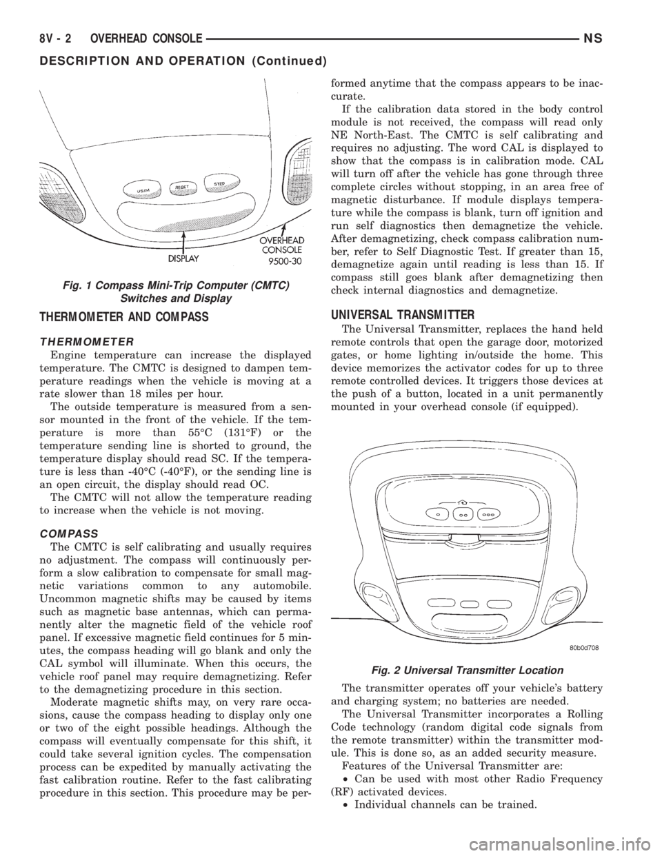
three buttons used to select various functions. The
CMTC selector buttons will not operate until the
ignition is in the RUN position (Fig. 1).
When the ignition switch is first turned to the
RUN position the CMTC display;
²Blanks momentarily
²All segments of the VFD will light for one sec-
ond
²Blanks momentarily
²Returns to the last mode setting selected before
the ignition was last switched OFF.
NSOVERHEAD CONSOLE 8V - 1
Page 552 of 1938
THERMOMETER AND COMPASS
THERMOMETER
Engine temperature can increase the displayed
temperature. The CMTC is designed to dampen tem-
perature readings when the vehicle is moving at a
rate slower than 18 miles per hour.
The outside temperature is measured from a sen-
sor mounted in the front of the vehicle. If the tem-
perature is more than 55ÉC (131ÉF) or the
temperature sending line is shorted to ground, the
temperature display should read SC. If the tempera-
ture is less than -40ÉC (-40ÉF), or the sending line is
an open circuit, the display should read OC.
The CMTC will not allow the temperature reading
to increase when the vehicle is not moving.
COMPASS
The CMTC is self calibrating and usually requires
no adjustment. The compass will continuously per-
form a slow calibration to compensate for small mag-
netic variations common to any automobile.
Uncommon magnetic shifts may be caused by items
such as magnetic base antennas, which can perma-
nently alter the magnetic field of the vehicle roof
panel. If excessive magnetic field continues for 5 min-
utes, the compass heading will go blank and only the
CAL symbol will illuminate. When this occurs, the
vehicle roof panel may require demagnetizing. Refer
to the demagnetizing procedure in this section.
Moderate magnetic shifts may, on very rare occa-
sions, cause the compass heading to display only one
or two of the eight possible headings. Although the
compass will eventually compensate for this shift, it
could take several ignition cycles. The compensation
process can be expedited by manually activating the
fast calibration routine. Refer to the fast calibrating
procedure in this section. This procedure may be per-formed anytime that the compass appears to be inac-
curate.
If the calibration data stored in the body control
module is not received, the compass will read only
NE North-East. The CMTC is self calibrating and
requires no adjusting. The word CAL is displayed to
show that the compass is in calibration mode. CAL
will turn off after the vehicle has gone through three
complete circles without stopping, in an area free of
magnetic disturbance. If module displays tempera-
ture while the compass is blank, turn off ignition and
run self diagnostics then demagnetize the vehicle.
After demagnetizing, check compass calibration num-
ber, refer to Self Diagnostic Test. If greater than 15,
demagnetize again until reading is less than 15. If
compass still goes blank after demagnetizing then
check internal diagnostics and demagnetize.
UNIVERSAL TRANSMITTER
The Universal Transmitter, replaces the hand held
remote controls that open the garage door, motorized
gates, or home lighting in/outside the home. This
device memorizes the activator codes for up to three
remote controlled devices. It triggers those devices at
the push of a button, located in a unit permanently
mounted in your overhead console (if equipped).
The transmitter operates off your vehicle's battery
and charging system; no batteries are needed.
The Universal Transmitter incorporates a Rolling
Code technology (random digital code signals from
the remote transmitter) within the transmitter mod-
ule. This is done so, as an added security measure.
Features of the Universal Transmitter are:
²Can be used with most other Radio Frequency
(RF) activated devices.
²Individual channels can be trained.
Fig. 1 Compass Mini-Trip Computer (CMTC)
Switches and Display
Fig. 2 Universal Transmitter Location
8V - 2 OVERHEAD CONSOLENS
DESCRIPTION AND OPERATION (Continued)