display CHRYSLER VOYAGER 1996 Owner's Guide
[x] Cancel search | Manufacturer: CHRYSLER, Model Year: 1996, Model line: VOYAGER, Model: CHRYSLER VOYAGER 1996Pages: 1938, PDF Size: 55.84 MB
Page 553 of 1938
²Stores transmitter data in permanent memory -
retraining is not required even if the battery dies or
is disconnected.
To operate, simply press the appropriate button on
the Universal Transmitter. The red LED will light up
while the signal is being transmitted.
NOTE: For security reasons, you are able to erase
the trained frequencies.
DIAGNOSIS AND TESTING
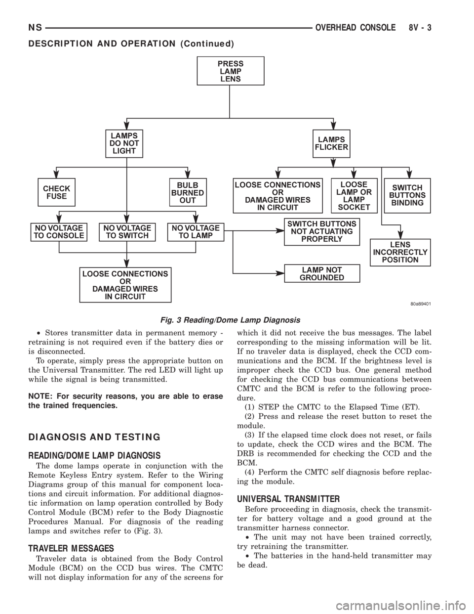
READING/DOME LAMP DIAGNOSIS
The dome lamps operate in conjunction with the
Remote Keyless Entry system. Refer to the Wiring
Diagrams group of this manual for component loca-
tions and circuit information. For additional diagnos-
tic information on lamp operation controlled by Body
Control Module (BCM) refer to the Body Diagnostic
Procedures Manual. For diagnosis of the reading
lamps and switches refer to (Fig. 3).
TRAVELER MESSAGES
Traveler data is obtained from the Body Control
Module (BCM) on the CCD bus wires. The CMTC
will not display information for any of the screens forwhich it did not receive the bus messages. The label
corresponding to the missing information will be lit.
If no traveler data is displayed, check the CCD com-
munications and the BCM. If the brightness level is
improper check the CCD bus. One general method
for checking the CCD bus communications between
CMTC and the BCM is refer to the following proce-
dure.
(1) STEP the CMTC to the Elapsed Time (ET).
(2) Press and release the reset button to reset the
module.
(3) If the elapsed time clock does not reset, or fails
to update, check the CCD wires and the BCM. The
DRB is recommended for checking the CCD and the
BCM.
(4) Perform the CMTC self diagnosis before replac-
ing the module.
UNIVERSAL TRANSMITTER
Before proceeding in diagnosis, check the transmit-
ter for battery voltage and a good ground at the
transmitter harness connector.
²The unit may not have been trained correctly,
try retraining the transmitter.
²The batteries in the hand-held transmitter may
be dead.
Fig. 3 Reading/Dome Lamp Diagnosis
NSOVERHEAD CONSOLE 8V - 3
DESCRIPTION AND OPERATION (Continued)
Page 554 of 1938
²Rotate your hand-held transmitter end-over-end
and train again. For best results, place the end oppo-
site from the battery compartment against the uni-
versal transmitter while training.
²The frequency of the hand-held transmitter may
not be in the desired frequencies between 286MHz
and 399MHz set by FCC.
SERVICE PROCEDURES
COMPASS CALIBRATION PROCEDURE
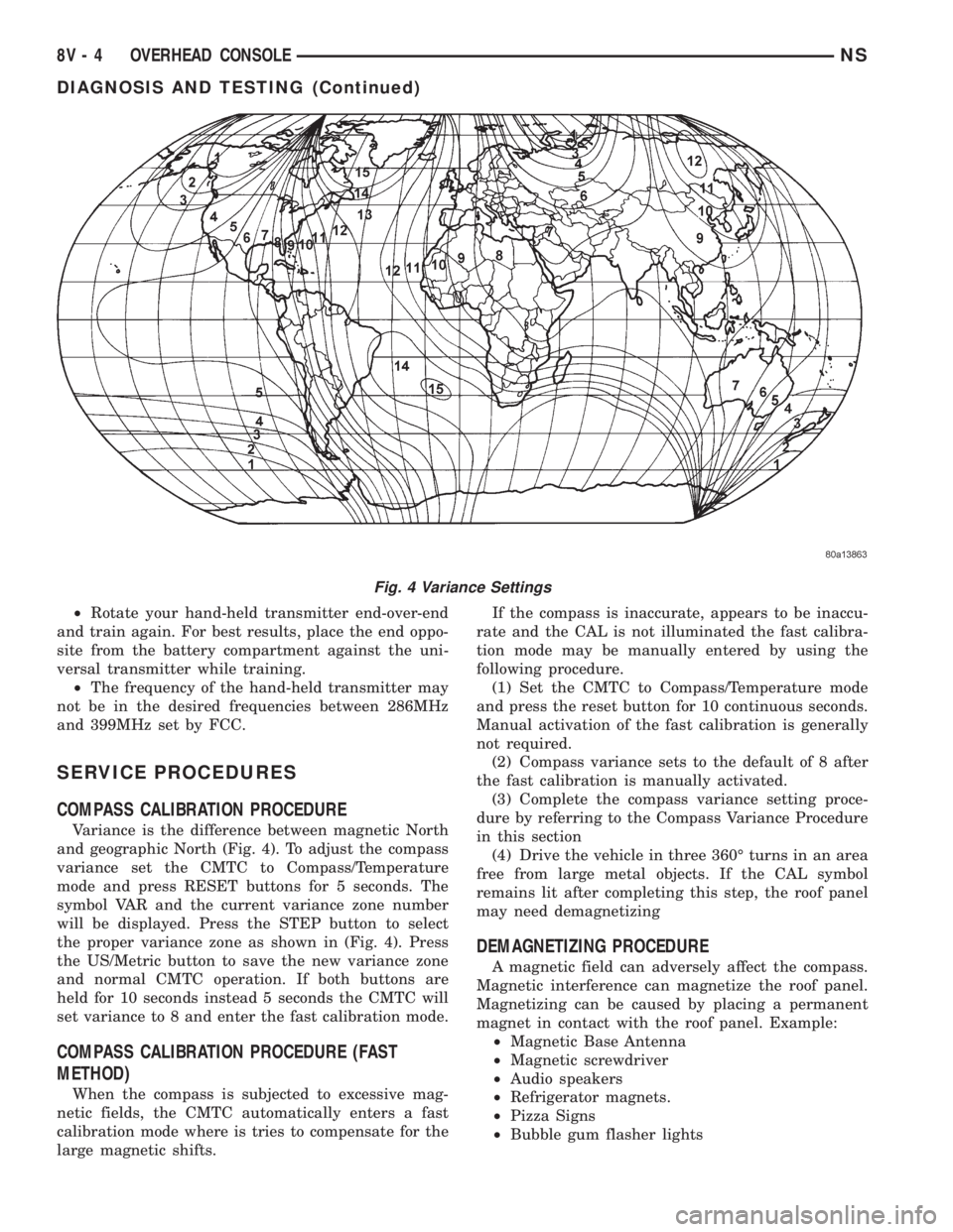
Variance is the difference between magnetic North
and geographic North (Fig. 4). To adjust the compass
variance set the CMTC to Compass/Temperature
mode and press RESET buttons for 5 seconds. The
symbol VAR and the current variance zone number
will be displayed. Press the STEP button to select
the proper variance zone as shown in (Fig. 4). Press
the US/Metric button to save the new variance zone
and normal CMTC operation. If both buttons are
held for 10 seconds instead 5 seconds the CMTC will
set variance to 8 and enter the fast calibration mode.
COMPASS CALIBRATION PROCEDURE (FAST
METHOD)
When the compass is subjected to excessive mag-
netic fields, the CMTC automatically enters a fast
calibration mode where is tries to compensate for the
large magnetic shifts.If the compass is inaccurate, appears to be inaccu-
rate and the CAL is not illuminated the fast calibra-
tion mode may be manually entered by using the
following procedure.
(1) Set the CMTC to Compass/Temperature mode
and press the reset button for 10 continuous seconds.
Manual activation of the fast calibration is generally
not required.
(2) Compass variance sets to the default of 8 after
the fast calibration is manually activated.
(3) Complete the compass variance setting proce-
dure by referring to the Compass Variance Procedure
in this section
(4) Drive the vehicle in three 360É turns in an area
free from large metal objects. If the CAL symbol
remains lit after completing this step, the roof panel
may need demagnetizing
DEMAGNETIZING PROCEDURE
A magnetic field can adversely affect the compass.
Magnetic interference can magnetize the roof panel.
Magnetizing can be caused by placing a permanent
magnet in contact with the roof panel. Example:
²Magnetic Base Antenna
²Magnetic screwdriver
²Audio speakers
²Refrigerator magnets.
²Pizza Signs
²Bubble gum flasher lights
Fig. 4 Variance Settings
8V - 4 OVERHEAD CONSOLENS
DIAGNOSIS AND TESTING (Continued)
Page 555 of 1938
Removing magnetic interfering objects will usually
restore normal compass operation. If the compass
display remains blank while the CAL label is illumi-
nated, then the roof panel requires demagnetizing. To
demagnetize use Special Tool 6029 for demagnetizing
the roof panel. The demagnetizing procedure will
demagnetize the roof and mounting screws in the
overhead console. It is important that you follow the
instructions below exactly. The mounting screws and
the mounting brackets around the compass area are
steel, and therefore aid in the demagnetizing of the
roof panel.
(1) Be sure the ignition switch is in the OFF posi-
tion before you begin the demagnetize procedure.
(2) Plug the demagnetizing tool into a standard
110/115 volt AC outlet, keeping the demagnetizing
tool at least 12 inches away from the compass area
when plugging it in.
(3) Slowly approach and contact the console
mounting screw with the plastic coated tip of the tool
for at least two seconds.
(4) With the demagnetizing tool still energized,
slowly back it away from the screw until the tip is at
least 12 inches from the screw head.
(5) Repeat the last step with all the console
mounting screws.
(6) After you have pulled at least 12 inches from
the last screw, remove the demagnetizing tool from
inside vehicle and disconnect it from the electrical
outlet.
(7) Place an 8 1/2 X 11 inch piece of paper length-
wise on the roof of vehicle directly above compass.
The purpose of the paper is to protect the roof panel
from scratches and define the area to be demagne-
tized.
(8) Plug in the demagnetizing tool, keeping it at
least two feet away from the compass unit.
(9) Slowly approach the center of the roof panel at
the windshield with the demagnetizing tool plugged
in.
(10) Contact the roof panel with the tip of the tool.
Using slow sweeping motions of 1/2 inch between
sweeps. Move the tool approximately four inches
either side of the center line and at least 11 inches
back from the windshield.
(11) With the demagnetizing tool still energized,
slowly back away from the roof panel until the tip is
at least two feet from the roof before unplugging the
tool.
(12) Recalibrate compass, refer to the compass cal-
ibration procedure in this section.
UNIVERSAL TRANSMITTER
TRAINING
(1) Turn off the engine.(2) Erase the factory test codes by pressing the
two outside buttons. Release the buttons when the
red light begins to flash (about 20 seconds).
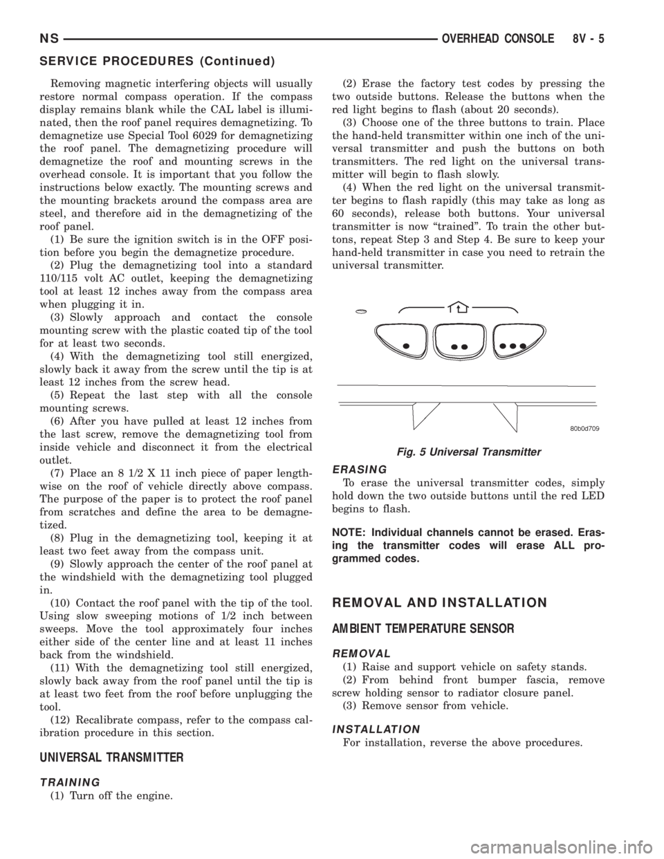
(3) Choose one of the three buttons to train. Place
the hand-held transmitter within one inch of the uni-
versal transmitter and push the buttons on both
transmitters. The red light on the universal trans-
mitter will begin to flash slowly.
(4) When the red light on the universal transmit-
ter begins to flash rapidly (this may take as long as
60 seconds), release both buttons. Your universal
transmitter is now ªtrainedº. To train the other but-
tons, repeat Step 3 and Step 4. Be sure to keep your
hand-held transmitter in case you need to retrain the
universal transmitter.
ERASING
To erase the universal transmitter codes, simply
hold down the two outside buttons until the red LED
begins to flash.
NOTE: Individual channels cannot be erased. Eras-
ing the transmitter codes will erase ALL pro-
grammed codes.
REMOVAL AND INSTALLATION
AMBIENT TEMPERATURE SENSOR
REMOVAL
(1) Raise and support vehicle on safety stands.
(2) From behind front bumper fascia, remove
screw holding sensor to radiator closure panel.
(3) Remove sensor from vehicle.
INSTALLATION
For installation, reverse the above procedures.
Fig. 5 Universal Transmitter
NSOVERHEAD CONSOLE 8V - 5
SERVICE PROCEDURES (Continued)
Page 1254 of 1938
VALVES AND VALVE SPRINGS
VALVE CLEANING
Clean all carbon deposits from the combustion
chambers, valve ports, valve stems, valve stem
guides and heads.
Clean all grime and gasket material from the
engine cylinder head machined gasket surfaces.
INSPECTION
Inspect for cracks in the combustion chambers and
valve ports.
Inspect for cracks on the exhaust seat.
Inspect for cracks in the gasket surface at each
coolant passage.
Inspect valves for burned, cracked or warped
heads.
Inspect for scuffed or bent valve stems.
Replace valves displaying any damage.
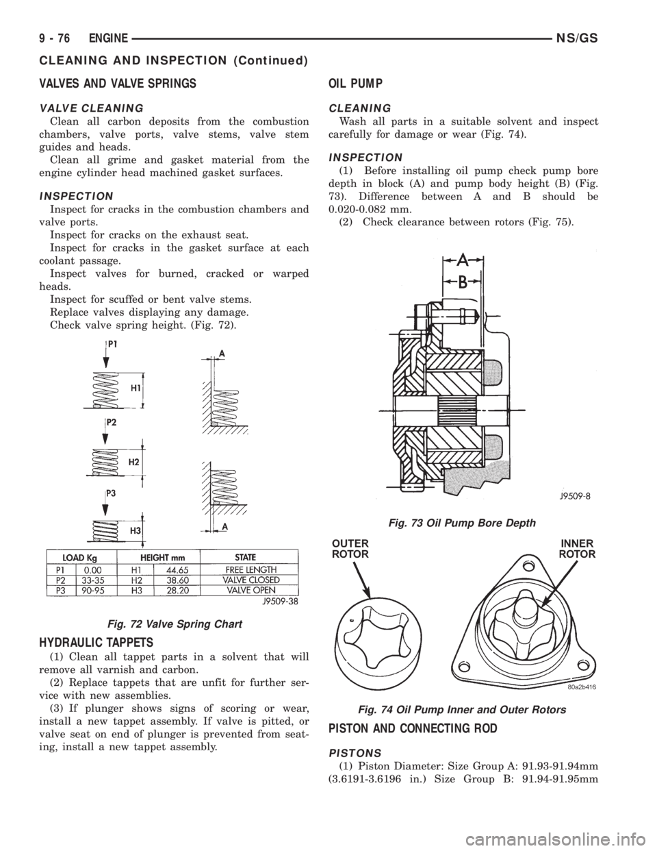
Check valve spring height. (Fig. 72).
HYDRAULIC TAPPETS
(1) Clean all tappet parts in a solvent that will
remove all varnish and carbon.
(2) Replace tappets that are unfit for further ser-
vice with new assemblies.
(3) If plunger shows signs of scoring or wear,
install a new tappet assembly. If valve is pitted, or
valve seat on end of plunger is prevented from seat-
ing, install a new tappet assembly.
OIL PUMP
CLEANING
Wash all parts in a suitable solvent and inspect
carefully for damage or wear (Fig. 74).
INSPECTION
(1) Before installing oil pump check pump bore
depth in block (A) and pump body height (B) (Fig.
73). Difference between A and B should be
0.020-0.082 mm.
(2) Check clearance between rotors (Fig. 75).
PISTON AND CONNECTING ROD
PISTONS
(1) Piston Diameter: Size Group A: 91.93-91.94mm
(3.6191-3.6196 in.) Size Group B: 91.94-91.95mm
Fig. 72 Valve Spring Chart
Fig. 73 Oil Pump Bore Depth
Fig. 74 Oil Pump Inner and Outer Rotors
9 - 76 ENGINENS/GS
CLEANING AND INSPECTION (Continued)
Page 1328 of 1938
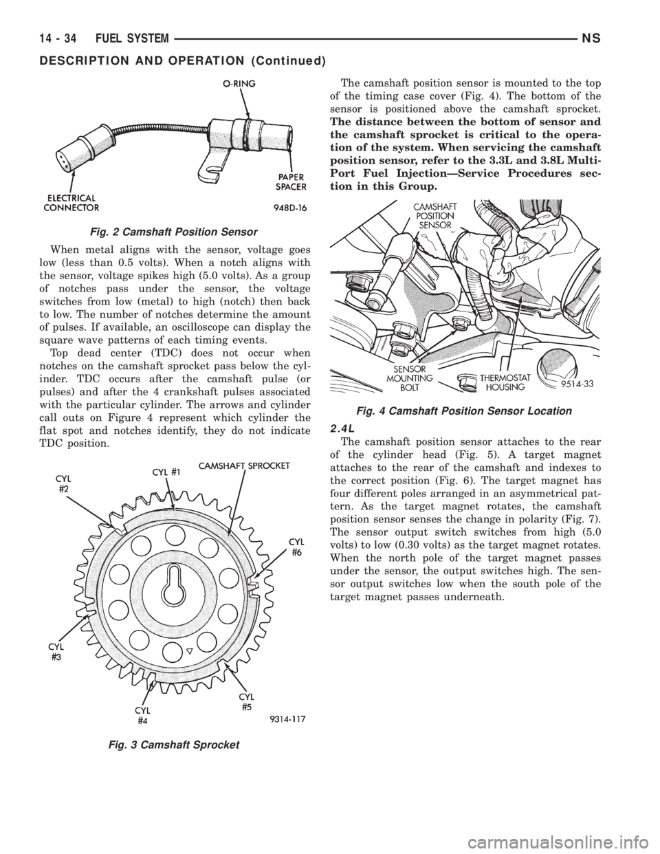
When metal aligns with the sensor, voltage goes
low (less than 0.5 volts). When a notch aligns with
the sensor, voltage spikes high (5.0 volts). As a group
of notches pass under the sensor, the voltage
switches from low (metal) to high (notch) then back
to low. The number of notches determine the amount
of pulses. If available, an oscilloscope can display the
square wave patterns of each timing events.
Top dead center (TDC) does not occur when
notches on the camshaft sprocket pass below the cyl-
inder. TDC occurs after the camshaft pulse (or
pulses) and after the 4 crankshaft pulses associated
with the particular cylinder. The arrows and cylinder
call outs on Figure 4 represent which cylinder the
flat spot and notches identify, they do not indicate
TDC position.The camshaft position sensor is mounted to the top
of the timing case cover (Fig. 4). The bottom of the
sensor is positioned above the camshaft sprocket.
The distance between the bottom of sensor and
the camshaft sprocket is critical to the opera-
tion of the system. When servicing the camshaft
position sensor, refer to the 3.3L and 3.8L Multi-
Port Fuel InjectionÐService Procedures sec-
tion in this Group.
2.4L
The camshaft position sensor attaches to the rear
of the cylinder head (Fig. 5). A target magnet
attaches to the rear of the camshaft and indexes to
the correct position (Fig. 6). The target magnet has
four different poles arranged in an asymmetrical pat-
tern. As the target magnet rotates, the camshaft
position sensor senses the change in polarity (Fig. 7).
The sensor output switch switches from high (5.0
volts) to low (0.30 volts) as the target magnet rotates.
When the north pole of the target magnet passes
under the sensor, the output switches high. The sen-
sor output switches low when the south pole of the
target magnet passes underneath.
Fig. 2 Camshaft Position Sensor
Fig. 3 Camshaft Sprocket
Fig. 4 Camshaft Position Sensor Location
14 - 34 FUEL SYSTEMNS
DESCRIPTION AND OPERATION (Continued)
Page 1330 of 1938
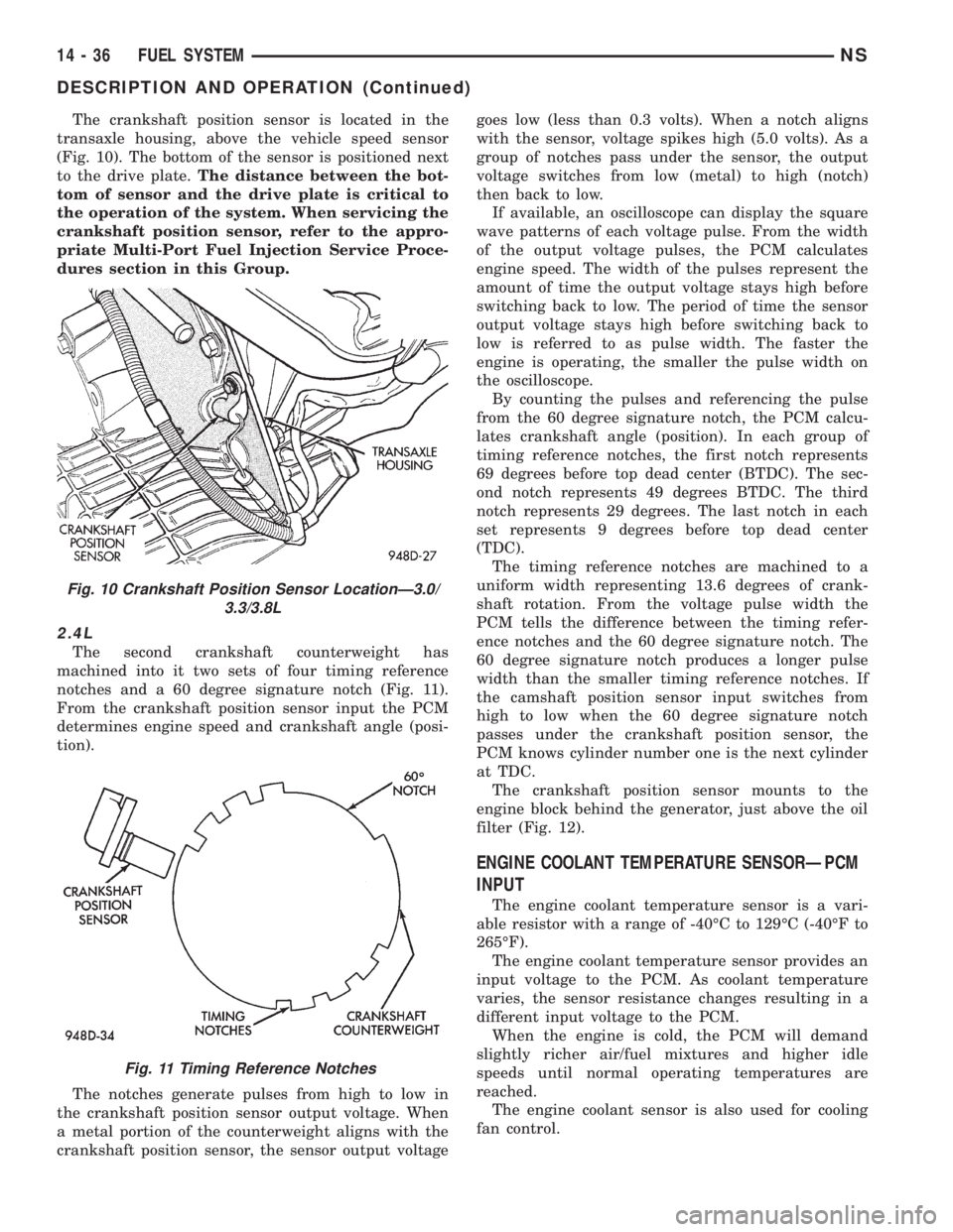
The crankshaft position sensor is located in the
transaxle housing, above the vehicle speed sensor
(Fig. 10). The bottom of the sensor is positioned next
to the drive plate.The distance between the bot-
tom of sensor and the drive plate is critical to
the operation of the system. When servicing the
crankshaft position sensor, refer to the appro-
priate Multi-Port Fuel Injection Service Proce-
dures section in this Group.
2.4L
The second crankshaft counterweight has
machined into it two sets of four timing reference
notches and a 60 degree signature notch (Fig. 11).
From the crankshaft position sensor input the PCM
determines engine speed and crankshaft angle (posi-
tion).
The notches generate pulses from high to low in
the crankshaft position sensor output voltage. When
a metal portion of the counterweight aligns with the
crankshaft position sensor, the sensor output voltagegoes low (less than 0.3 volts). When a notch aligns
with the sensor, voltage spikes high (5.0 volts). As a
group of notches pass under the sensor, the output
voltage switches from low (metal) to high (notch)
then back to low.
If available, an oscilloscope can display the square
wave patterns of each voltage pulse. From the width
of the output voltage pulses, the PCM calculates
engine speed. The width of the pulses represent the
amount of time the output voltage stays high before
switching back to low. The period of time the sensor
output voltage stays high before switching back to
low is referred to as pulse width. The faster the
engine is operating, the smaller the pulse width on
the oscilloscope.
By counting the pulses and referencing the pulse
from the 60 degree signature notch, the PCM calcu-
lates crankshaft angle (position). In each group of
timing reference notches, the first notch represents
69 degrees before top dead center (BTDC). The sec-
ond notch represents 49 degrees BTDC. The third
notch represents 29 degrees. The last notch in each
set represents 9 degrees before top dead center
(TDC).
The timing reference notches are machined to a
uniform width representing 13.6 degrees of crank-
shaft rotation. From the voltage pulse width the
PCM tells the difference between the timing refer-
ence notches and the 60 degree signature notch. The
60 degree signature notch produces a longer pulse
width than the smaller timing reference notches. If
the camshaft position sensor input switches from
high to low when the 60 degree signature notch
passes under the crankshaft position sensor, the
PCM knows cylinder number one is the next cylinder
at TDC.
The crankshaft position sensor mounts to the
engine block behind the generator, just above the oil
filter (Fig. 12).
ENGINE COOLANT TEMPERATURE SENSORÐPCM
INPUT
The engine coolant temperature sensor is a vari-
able resistor with a range of -40ÉC to 129ÉC (-40ÉF to
265ÉF).
The engine coolant temperature sensor provides an
input voltage to the PCM. As coolant temperature
varies, the sensor resistance changes resulting in a
different input voltage to the PCM.
When the engine is cold, the PCM will demand
slightly richer air/fuel mixtures and higher idle
speeds until normal operating temperatures are
reached.
The engine coolant sensor is also used for cooling
fan control.
Fig. 10 Crankshaft Position Sensor LocationÐ3.0/
3.3/3.8L
Fig. 11 Timing Reference Notches
14 - 36 FUEL SYSTEMNS
DESCRIPTION AND OPERATION (Continued)
Page 1356 of 1938
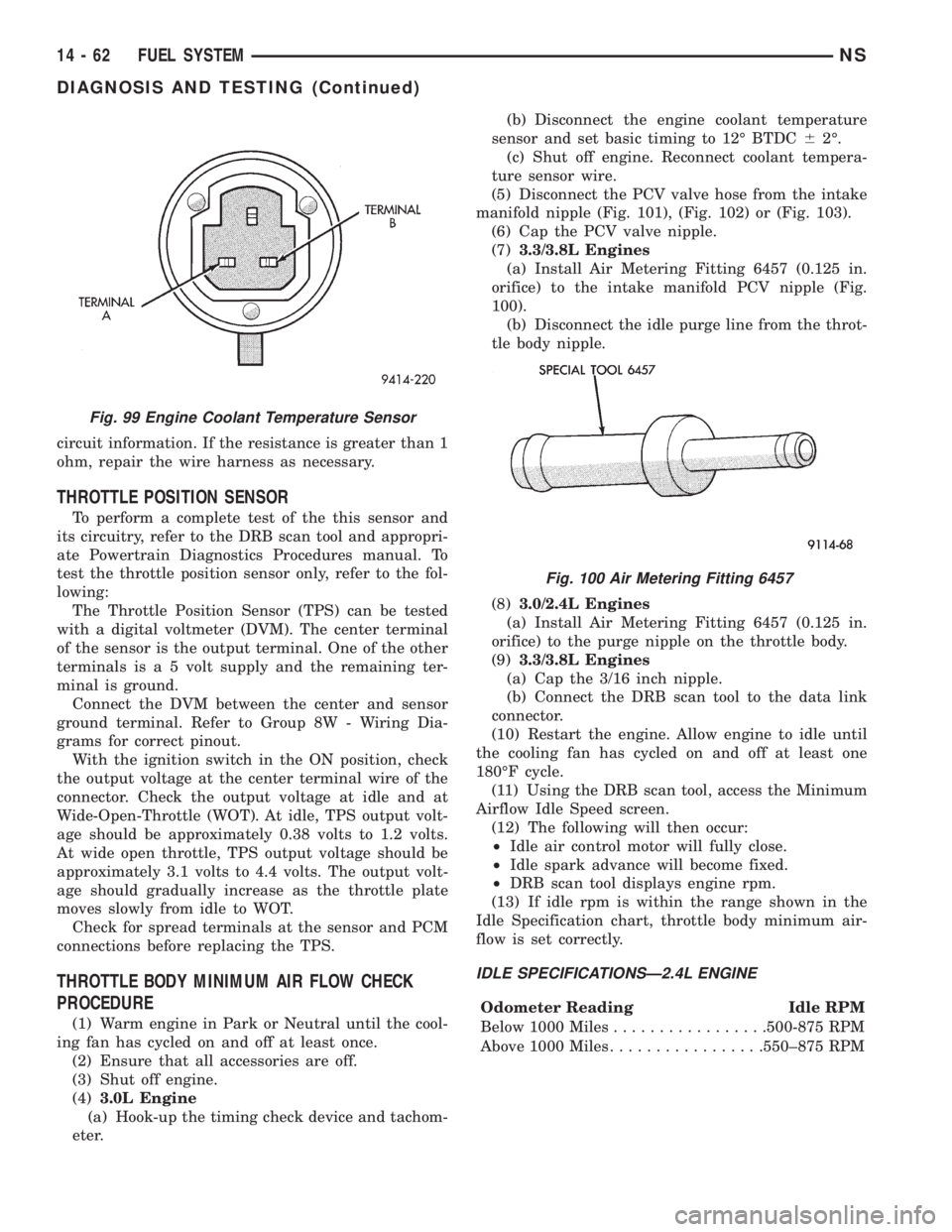
circuit information. If the resistance is greater than 1
ohm, repair the wire harness as necessary.
THROTTLE POSITION SENSOR
To perform a complete test of the this sensor and
its circuitry, refer to the DRB scan tool and appropri-
ate Powertrain Diagnostics Procedures manual. To
test the throttle position sensor only, refer to the fol-
lowing:
The Throttle Position Sensor (TPS) can be tested
with a digital voltmeter (DVM). The center terminal
of the sensor is the output terminal. One of the other
terminals is a 5 volt supply and the remaining ter-
minal is ground.
Connect the DVM between the center and sensor
ground terminal. Refer to Group 8W - Wiring Dia-
grams for correct pinout.
With the ignition switch in the ON position, check
the output voltage at the center terminal wire of the
connector. Check the output voltage at idle and at
Wide-Open-Throttle (WOT). At idle, TPS output volt-
age should be approximately 0.38 volts to 1.2 volts.
At wide open throttle, TPS output voltage should be
approximately 3.1 volts to 4.4 volts. The output volt-
age should gradually increase as the throttle plate
moves slowly from idle to WOT.
Check for spread terminals at the sensor and PCM
connections before replacing the TPS.
THROTTLE BODY MINIMUM AIR FLOW CHECK
PROCEDURE
(1) Warm engine in Park or Neutral until the cool-
ing fan has cycled on and off at least once.
(2) Ensure that all accessories are off.
(3) Shut off engine.
(4)3.0L Engine
(a) Hook-up the timing check device and tachom-
eter.(b) Disconnect the engine coolant temperature
sensor and set basic timing to 12É BTDC62É.
(c) Shut off engine. Reconnect coolant tempera-
ture sensor wire.
(5) Disconnect the PCV valve hose from the intake
manifold nipple (Fig. 101), (Fig. 102) or (Fig. 103).
(6) Cap the PCV valve nipple.
(7)3.3/3.8L Engines
(a) Install Air Metering Fitting 6457 (0.125 in.
orifice) to the intake manifold PCV nipple (Fig.
100).
(b) Disconnect the idle purge line from the throt-
tle body nipple.
(8)3.0/2.4L Engines
(a) Install Air Metering Fitting 6457 (0.125 in.
orifice) to the purge nipple on the throttle body.
(9)3.3/3.8L Engines
(a) Cap the 3/16 inch nipple.
(b) Connect the DRB scan tool to the data link
connector.
(10) Restart the engine. Allow engine to idle until
the cooling fan has cycled on and off at least one
180ÉF cycle.
(11) Using the DRB scan tool, access the Minimum
Airflow Idle Speed screen.
(12) The following will then occur:
²Idle air control motor will fully close.
²Idle spark advance will become fixed.
²DRB scan tool displays engine rpm.
(13) If idle rpm is within the range shown in the
Idle Specification chart, throttle body minimum air-
flow is set correctly.
IDLE SPECIFICATIONSÐ2.4L ENGINE
Odometer Reading Idle RPM
Below 1000 Miles.................500-875 RPM
Above 1000 Miles.................550±875 RPM
Fig. 99 Engine Coolant Temperature Sensor
Fig. 100 Air Metering Fitting 6457
14 - 62 FUEL SYSTEMNS
DIAGNOSIS AND TESTING (Continued)
Page 1409 of 1938

Connect the DVM between the center and sensor
ground terminal. Refer to Group 8W - Wiring Dia-
grams for correct pinout.
With the ignition switch in the ON position, check
the output voltage at the center terminal wire of the
connector. Check the output voltage at idle and at
Wide-Open-Throttle (WOT). At idle, TPS output volt-
age should be approximately 0.38 volts to 1.2 volts.
At wide open throttle, TPS output voltage should be
approximately 3.1 volts to 4.4 volts. The output volt-
age should gradually increase as the throttle plate
moves slowly from idle to WOT.
Check for spread terminals at the sensor and PCM
connections before replacing the TPS.
THROTTLE BODY MINIMUM AIR FLOW
(1) Turn ignition key to Off.
(2) D
isconnect the PCV valve hose from the intake
manifold nipple (Fig. 31). Cap the PCV vacuum nipple.
(3) Disconnect purge hose from the nipple on the
throttle body (Fig. 32).(4) Use a piece of hose to attach Air Metering Ori-
fice 6457 (0.125 in. orifice) to the purge nipple on the
throttle body (Fig. 33).
(5) Ensure that all accessories are off.
(6) Connect the DRB scan tool to the data link
connector inside the passenger compartment.
(7) Run engine in Park or Neutral until the cooling
fan has cycled on and off at least once (180ÉF).
(8) Using the DRB scan tool, access Minimum Air-
flow Idle Speed.
(9) The following will then occur:
²Idle air control motor will fully close
²Idle spark advance will become fixed
²PCM will go open loop enriched
²DRB scan tool displays engine RPM
(10) If idle RPM is within the range shown in the
Idle Specification chart, throttle body minimum air-
flow is set correctly.IDLE SPECIFICATION Ð2.0L ENGINE
Odometer Reading Idle RPM
Below 1000 Miles...............550±1300 RPM
Above 1000 Miles...............600±1300 RPM
(11) If idle RPM is above specifications, use the
DRB scan tool to check idle air control motor opera-
tion. If idle air control motor is OK, replace throttle
body. If idle air flow is below specification, shut off
the engine and clean the throttle body as follows:
WARNING: CLEAN THROTTLE BODY IN A WELL
VENTILATED AREA. WEAR RUBBER OR BUTYL
GLOVES, DO NOT LET MOPAR PARTS CLEANER
COME IN CONTACT WITH EYES OR SKIN. AVOID
INGESTING THE CLEANER. WASH THOROUGHLY
AFTER USING CLEANER.
Fig. 31 PCV Vacuum Nipple
Fig. 32 Purge Hose
Fig. 33 Orifice 6457 Attached to Purge Nipple
NS/GSFUEL SYSTEMÐ2.5L DIESEL ENGINE/2.0L GAS ENGINE 14 - 41
DIAGNOSIS AND TESTING (Continued)
Page 1525 of 1938
Inspect all valve springs for distortion and col-
lapsed coils. Inspect all valves and plugs for burrs,
nicks, and scores. Small nicks and scores may be
removed with crocus cloth, providing extreme care is
taken not to round off sharp edges. The sharpness of
these edges is vitally important. It prevents foreign
matter from lodging between valve and valve body.
This reduces the possibility of sticking. Inspect all
valves and plugs for freedom of operation in valve
body bores.
When bores, valves, and plugs are clean and dry,
the valves and plugs should fall freely in the bores.
The valve body bores do not change its dimensions
with use. Therefore, a valve body that was function-
ing properly when vehicle was new, will operate cor-
rectly if it is properly and thoroughly cleaned. There
is no need to replace valve body unless it is damaged
in handling.
ADJUSTMENTS
GEARSHIFT CABLE ADJUSTMENT
Lift and rotate the gearshift hand lever into the
park (P) gate position and remove the ignition key.
This confirms the shift lever is in the gated park (P)
position.
After confirming the park gate position, turn the
ignition switch. If the starter will operate, the park
gate position is correct. Move the shift lever into the
neutral (N) position. If the starter will operate in this
position, the linkage is properly adjusted. If the
starter fails to operate in either position, linkage
adjustment is required.
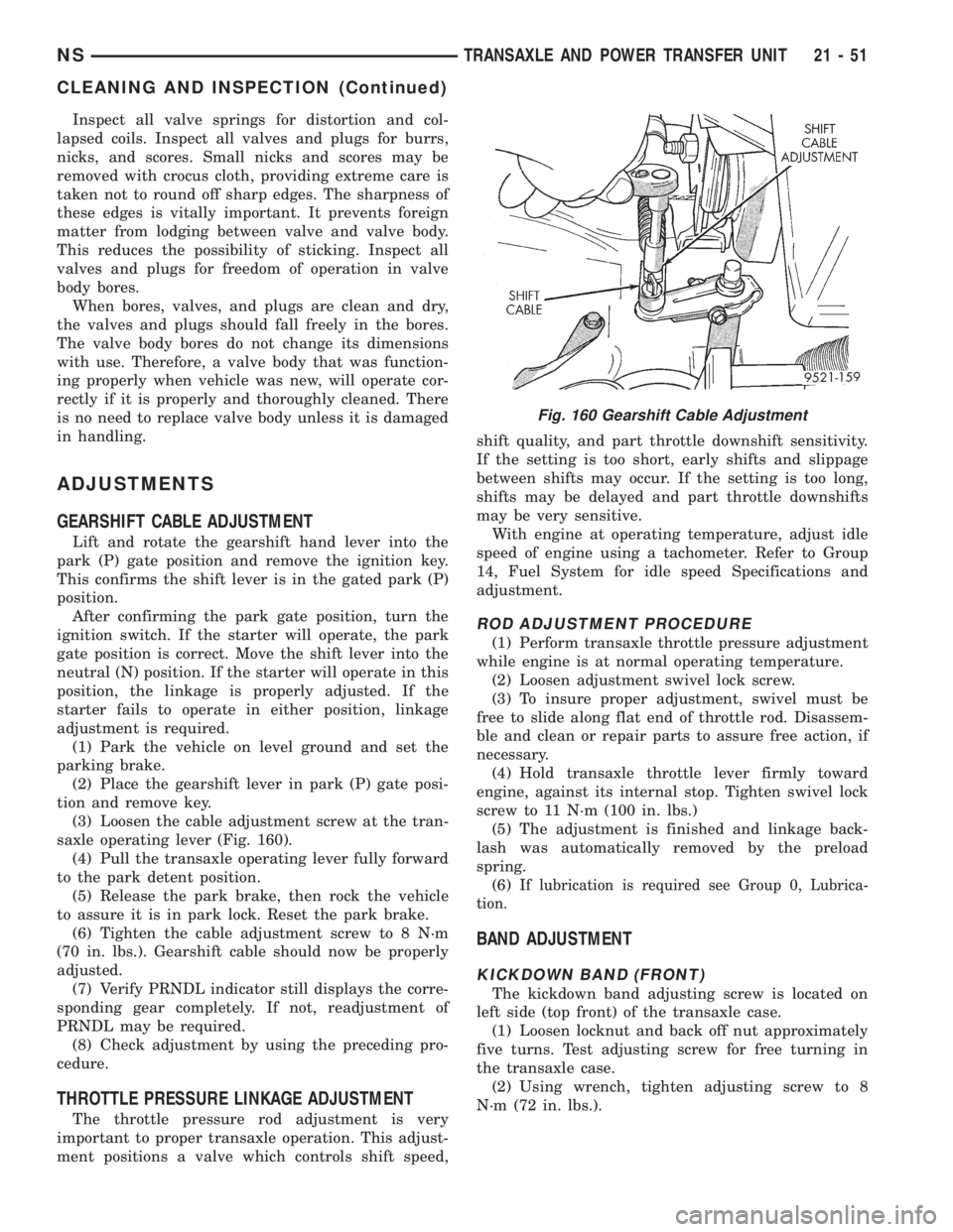
(1) Park the vehicle on level ground and set the
parking brake.
(2) Place the gearshift lever in park (P) gate posi-
tion and remove key.
(3) Loosen the cable adjustment screw at the tran-
saxle operating lever (Fig. 160).
(4) Pull the transaxle operating lever fully forward
to the park detent position.
(5) Release the park brake, then rock the vehicle
to assure it is in park lock. Reset the park brake.
(6) Tighten the cable adjustment screw to 8 N´m
(70 in. lbs.). Gearshift cable should now be properly
adjusted.
(7) Verify PRNDL indicator still displays the corre-
sponding gear completely. If not, readjustment of
PRNDL may be required.
(8) Check adjustment by using the preceding pro-
cedure.
THROTTLE PRESSURE LINKAGE ADJUSTMENT
The throttle pressure rod adjustment is very
important to proper transaxle operation. This adjust-
ment positions a valve which controls shift speed,shift quality, and part throttle downshift sensitivity.
If the setting is too short, early shifts and slippage
between shifts may occur. If the setting is too long,
shifts may be delayed and part throttle downshifts
may be very sensitive.
With engine at operating temperature, adjust idle
speed of engine using a tachometer. Refer to Group
14, Fuel System for idle speed Specifications and
adjustment.
ROD ADJUSTMENT PROCEDURE
(1) Perform transaxle throttle pressure adjustment
while engine is at normal operating temperature.
(2) Loosen adjustment swivel lock screw.
(3) To insure proper adjustment, swivel must be
free to slide along flat end of throttle rod. Disassem-
ble and clean or repair parts to assure free action, if
necessary.
(4) Hold transaxle throttle lever firmly toward
engine, against its internal stop. Tighten swivel lock
screw to 11 N´m (100 in. lbs.)
(5) The adjustment is finished and linkage back-
lash was automatically removed by the preload
spring.
(6) I
f lubrication is required see Group 0, Lubrica-
tion.
BAND ADJUSTMENT
KICKDOWN BAND (FRONT)
The kickdown band adjusting screw is located on
left side (top front) of the transaxle case.
(1) Loosen locknut and back off nut approximately
five turns. Test adjusting screw for free turning in
the transaxle case.
(2) Using wrench, tighten adjusting screw to 8
N´m (72 in. lbs.).
Fig. 160 Gearshift Cable Adjustment
NSTRANSAXLE AND POWER TRANSFER UNIT 21 - 51
CLEANING AND INSPECTION (Continued)
Page 1553 of 1938
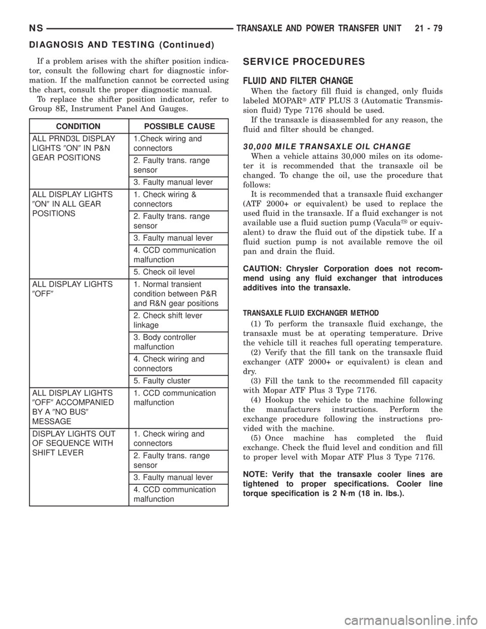
If a problem arises with the shifter position indica-
tor, consult the following chart for diagnostic infor-
mation. If the malfunction cannot be corrected using
the chart, consult the proper diagnostic manual.
To replace the shifter position indicator, refer to
Group 8E, Instrument Panel And Gauges.SERVICE PROCEDURES
FLUID AND FILTER CHANGE
When the factory fill fluid is changed, only fluids
labeled MOPARtATF PLUS 3 (Automatic Transmis-
sion fluid) Type 7176 should be used.
If the transaxle is disassembled for any reason, the
fluid and filter should be changed.
30,000 MILE TRANSAXLE OIL CHANGE
When a vehicle attains 30,000 miles on its odome-
ter it is recommended that the transaxle oil be
changed. To change the oil, use the procedure that
follows:
It is recommended that a transaxle fluid exchanger
(ATF 2000+ or equivalent) be used to replace the
used fluid in the transaxle. If a fluid exchanger is not
available use a fluid suction pump (Vaculayor equiv-
alent) to draw the fluid out of the dipstick tube. If a
fluid suction pump is not available remove the oil
pan and drain the fluid.
CAUTION: Chrysler Corporation does not recom-
mend using any fluid exchanger that introduces
additives into the transaxle.
TRANSAXLE FLUID EXCHANGER METHOD
(1) To perform the transaxle fluid exchange, the
transaxle must be at operating temperature. Drive
the vehicle till it reaches full operating temperature.
(2) Verify that the fill tank on the transaxle fluid
exchanger (ATF 2000+ or equivalent) is clean and
dry.
(3) Fill the tank to the recommended fill capacity
with Mopar ATF Plus 3 Type 7176.
(4) Hookup the vehicle to the machine following
the manufacturers instructions. Perform the
exchange procedure following the instructions pro-
vided with the machine.
(5) Once machine has completed the fluid
exchange. Check the fluid level and condition and fill
to proper level with Mopar ATF Plus 3 Type 7176.
NOTE: Verify that the transaxle cooler lines are
tightened to proper specifications. Cooler line
torque specification is 2 N´m (18 in. lbs.).
CONDITION POSSIBLE CAUSE
ALL PRND3L DISPLAY
LIGHTS9ON9IN P&N
GEAR POSITIONS1.Check wiring and
connectors
2. Faulty trans. range
sensor
3. Faulty manual lever
ALL DISPLAY LIGHTS
9ON9IN ALL GEAR
POSITIONS1. Check wiring &
connectors
2. Faulty trans. range
sensor
3. Faulty manual lever
4. CCD communication
malfunction
5. Check oil level
ALL DISPLAY LIGHTS
9OFF91. Normal transient
condition between P&R
and R&N gear positions
2. Check shift lever
linkage
3. Body controller
malfunction
4. Check wiring and
connectors
5. Faulty cluster
ALL DISPLAY LIGHTS
9OFF9ACCOMPANIED
BY A9NO BUS9
MESSAGE1. CCD communication
malfunction
DISPLAY LIGHTS OUT
OF SEQUENCE WITH
SHIFT LEVER1. Check wiring and
connectors
2. Faulty trans. range
sensor
3. Faulty manual lever
4. CCD communication
malfunction
NSTRANSAXLE AND POWER TRANSFER UNIT 21 - 79
DIAGNOSIS AND TESTING (Continued)