wheel bolts CHRYSLER VOYAGER 1996 Owner's Manual
[x] Cancel search | Manufacturer: CHRYSLER, Model Year: 1996, Model line: VOYAGER, Model: CHRYSLER VOYAGER 1996Pages: 1938, PDF Size: 55.84 MB
Page 87 of 1938
The caliper is a one piece casting with the inboard
side containing a single piston cylinder bore.
The phenolic piston is 60 mm (2.36 inch) in diam-
eter.
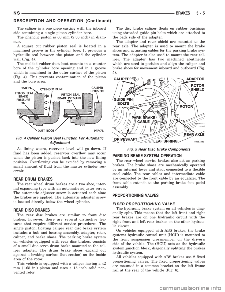
A square cut rubber piston seal is located in a
machined groove in the cylinder bore. It provides a
hydraulic seal between the piston and the cylinder
wall (Fig. 4).
The molded rubber dust boot mounts in a counter
bore of the cylinder bore opening and in a groove
which is machined in the outer surface of the piston
(Fig. 4). This prevents contamination of the piston
and the bore area.
As lining wears, reservoir level will go down. If
fluid has been added, reservoir overflow may occur
when the piston is pushed back into the new lining
position. Overflowing can be avoided by removing a
small amount of fluid from the master cylinder res-
ervoir.
REAR DRUM BRAKES
The rear wheel drum brakes are a two shoe, inter-
nal expanding type with an automatic adjuster screw.
The automatic adjuster screw is actuated each time
the brakes are applied. The automatic adjuster screw
is located directly below the wheel cylinder.
REAR DISC BRAKES
The rear disc brakes are similar to front disc
brakes, however, there are several distinctive fea-
tures that require different service procedures. The
single piston, floating caliper rear disc brake system
includes a hub and bearing assembly, adapter, rotor,
caliper, and brake shoes. The parking brake system
on vehicles equipped with rear disc brakes, consists
of a small duo-servo drum brake mounted to the cal-
iper adapter. The drum brake shoes expand out
against a braking surface (hat section) on the inside
area of the rotor.
This vehicle is equipped with a caliper having a 42
mm (1.65 in.) piston and uses a 15 inch solid non-
vented rotor.The disc brake caliper floats on rubber bushings
using threaded guide pin bolts which are attached to
the back side of the adapter.
The adapter and rotor shield are mounted to the
rear axle. The adapter is used to mount the brake
shoes and actuating cables for the parking brake sys-
tem. The adapter is also used to mount the rear cal-
iper. The adapter has two machined abutments
which are used to position and align the caliper and
brake shoes for movement inboard and outboard (Fig.
5).
PARKING BRAKE SYSTEM OPERATION
The rear wheel service brakes also act as parking
brakes. The brake shoes are mechanically operated
by an internal lever and strut connected to a flexible
steel cable. The rear cables and intermediate cable
are connected to the front cable by an equalizer. The
front cable extends to the parking brake foot pedal
assembly.
PROPORTIONING VALVES
FIXED PROPORTIONING VALVE
The hydraulic brake system on all vehicles is diag-
onally split. This means that the left front and right
rear brakes are on one hydraulic circuit with the
right front and left rear brakes on the other hydrau-
lic circuit.
On vehicles equipped with ABS brakes, the brake
systems hydraulic control unit (HCU) is mounted to
the front suspension crossmember on the driver's
side of the vehicle. The (HCU) acts as the hydraulic
system junction block, diagonally splitting the brakes
hydraulic system.
All vehicles equipped with ABS brakes use 2 fixed
proportioning valves. The fixed proportioning valves
are mounted in a common bracket on the left frame
rail at the rear of the vehicle (Fig. 6).
Fig. 4 Caliper Piston Seal Function For Automatic
Adjustment
Fig. 5 Rear Disc Brake Components
NSBRAKES 5 - 5
DESCRIPTION AND OPERATION (Continued)
Page 91 of 1938

normal. This may indicate:(1)Abnormal loss of
brake fluid in the master cylinder fluid reservoir
resulting from a leak in the hydraulic system.(2)
Brake shoe linings which have worn to a point
requiring replacement.
As the brake fluid drops below the minimum level,
the brake fluid level sensor closes to ground the
brake warning light circuit. This will turn on the red
brake warning light. At this time, master cylinder
fluid reservoir should be checked and filled to the full
mark with DOT 3 brake fluid.If brake fluid level
has dropped below the add line in the master
cylinder fluid reservoir, the entire brake
hydraulic system should be checked for evi-
dence of a leak.
STOP LAMP SWITCH
The stop lamp switch controls operation of the
vehicles stop lamps. Also, if the vehicle is equippedwith speed control, the stop lamp switch will deacti-
vate speed control when the brake pedal is
depressed.
The stop lamp switch controls operation of the
right and left tail, stop and turn signal lamp and
CHMSL lamp, by supplying battery current to these
lamps.
The stop lamp switch controls the lamp operation
by opening and closing the electrical circuit to the
stop lamps.
HUB/BEARING REAR WHEEL
The rear hub and bearing assembly used on this
vehicle is serviceable only as a complete assembly. No
attempt should be made to disassemble a rear hub
and bearing assembly in an effort to repair it.
The rear hub and bearing assembly is attached to
the rear axle using 4 mounting bolts that are remov-
able from the back of the rear hub/bearing.
DIAGNOSIS AND TESTING
BRAKE SYSTEM BASIC DIAGNOSIS GUIDE
SYMPTOMCHART 1
MISC.
COND.CHART 2
WARNING
LIGHTCHART 3
POWER
BRAKESCHART 4
BRAKE
NOISECHART 5
WHEEL
BRAKES
Brake Warning Light On X NO NO
Excessive Pedal Travel 6 X NO O
Pedal Goes To The Floor 6 X
Stop Light On Without Brakes 3
All Brakes Drag 5
Rear Brakes Drag 2 NO NO
Grabby Brakes O X
Spongy Brake Pedal X NO
Premature Rear Brake Lockup 4 NO NO O
Excessive Pedal Effort 1 O
Rough Engine Idle NO O
Brake Chatter (Rough) NO NO X
Surge During Braking NO NO X
Noise During Braking NO NO X
Rattle Or Clunking Noise NO NO X
Pedal Pulsates During Braking NO NO X
Pull To Right Or Left NO NO X
No: Not A Possible Cause X: Most Likely Cause O: Possible Cause
NSBRAKES 5 - 9
DESCRIPTION AND OPERATION (Continued)
Page 99 of 1938
(4) Remove the 2 bolts (Fig. 19) attaching the pro-
portioning valve to the frame rail.
CAUTION: When lowering the proportioning valve,
care must be taken not to kink any of the chassis
brake lines.
(5) Carefully lower the proportioning valve for
clearance to install the proportioning valve test fit-
tings.
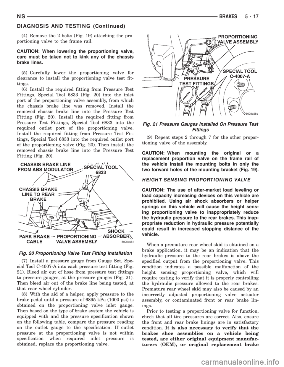
(6) Install the required fitting from Pressure Test
Fittings, Special Tool 6833 (Fig. 20) into the inlet
port of the proportioning valve assembly, from which
the chassis brake line was removed. Install the
removed chassis brake line into the Pressure Test
Fitting (Fig. 20). Install the required fitting from
Pressure Test Fittings, Special Tool 6833 into the
required outlet port of the proportioning valve.
Install the required fitting from Pressure Test Fit-
tings, Special Tool 6833 into the required outlet port
of the proportioning valve (Fig. 20). Then install the
removed chassis brake line into the Pressure Test
Fitting (Fig. 20).
(7) Install a pressure gauge from Gauge Set, Spe-
cial Tool C-4007-A into each pressure test fitting (Fig.
21). Bleed air out of hose from pressure test fittings
to pressure gauges, at the pressure gauges (Fig. 21).
Then bleed air out of the brake line being tested, at
that rear wheel cylinder.
(8) With the aid of a helper, apply pressure to the
brake pedal until a pressure of 6895 kPa (1000 psi) is
obtained on the proportioning valve inlet gauge.
Then based on the type of brake system the vehicle is
equipped with and the pressure specification shown
on the following table, compare the pressure reading
on the outlet gauge to the specification. If outlet
pressure at the proportioning valve is not within
specification when required inlet pressure is
obtained, replace the proportioning valve.(9) Repeat steps 2 through 7 for the other propor-
tioning valve of the assembly.
CAUTION: When mounting the original or a
replacement proportion valve on the frame rail of
the vehicle install the mounting bolts in only the
two forward holes of the mounting bracket (Fig. 19).
HEIGHT SENSING PROPORTIONING VALVE
CAUTION: The use of after-market load leveling or
load capacity increasing devices on this vehicle are
prohibited. Using air shock absorbers or helper
springs on this vehicle will cause the height sens-
ing proportioning valve to inappropriately reduce
the hydraulic pressure to the rear brakes. This inap-
propriate reduction in hydraulic pressure potentially
could result in increased stopping distance of the
vehicle.
When a premature rear wheel skid is obtained on a
brake application, it may be an indication that the
hydraulic pressure to the rear brakes is above the
specified output from the proportioning valve. This
condition indicates a possible malfunction of the
height sensing proportioning valve, which will
require testing to verify that it is properly controlling
the hydraulic pressure allowed to the rear brakes.
Premature rear wheel skid may also be caused by an
incorrectly adjusted proportioning valve actuator
assembly, or contaminated front or rear brake lin-
ings.
Prior to testing a proportioning valve for function,
check that all tire pressures are correct. Also, ensure
the front and rear brake linings are in satisfactory
condition.It is also necessary to verify that the
brakes shoe assemblies on a vehicle being
tested, are either original equipment manufac-
turers (OEM), or original replacement brake
Fig. 20 Proportioning Valve Test Fitting Installation
Fig. 21 Pressure Gauges Installed On Pressure Test
Fittings
NSBRAKES 5 - 17
DIAGNOSIS AND TESTING (Continued)
Page 110 of 1938
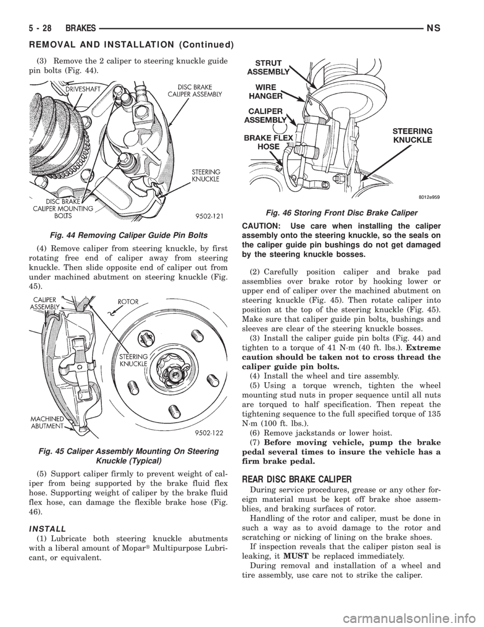
(3) Remove the 2 caliper to steering knuckle guide
pin bolts (Fig. 44).
(4) Remove caliper from steering knuckle, by first
rotating free end of caliper away from steering
knuckle. Then slide opposite end of caliper out from
under machined abutment on steering knuckle (Fig.
45).
(5) Support caliper firmly to prevent weight of cal-
iper from being supported by the brake fluid flex
hose. Supporting weight of caliper by the brake fluid
flex hose, can damage the flexible brake hose (Fig.
46).
INSTALL
(1) Lubricate both steering knuckle abutments
with a liberal amount of MopartMultipurpose Lubri-
cant, or equivalent.CAUTION: Use care when installing the caliper
assembly onto the steering knuckle, so the seals on
the caliper guide pin bushings do not get damaged
by the steering knuckle bosses.
(2) Carefully position caliper and brake pad
assemblies over brake rotor by hooking lower or
upper end of caliper over the machined abutment on
steering knuckle (Fig. 45). Then rotate caliper into
position at the top of the steering knuckle (Fig. 45).
Make sure that caliper guide pin bolts, bushings and
sleeves are clear of the steering knuckle bosses.
(3) Install the caliper guide pin bolts (Fig. 44) and
tighten to a torque of 41 N´m (40 ft. lbs.).Extreme
caution should be taken not to cross thread the
caliper guide pin bolts.
(4) Install the wheel and tire assembly.
(5) Using a torque wrench, tighten the wheel
mounting stud nuts in proper sequence until all nuts
are torqued to half specification. Then repeat the
tightening sequence to the full specified torque of 135
N´m (100 ft. lbs.).
(6) Remove jackstands or lower hoist.
(7)Before moving vehicle, pump the brake
pedal several times to insure the vehicle has a
firm brake pedal.
REAR DISC BRAKE CALIPER
During service procedures, grease or any other for-
eign material must be kept off brake shoe assem-
blies, and braking surfaces of rotor.
Handling of the rotor and caliper, must be done in
such a way as to avoid damage to the rotor and
scratching or nicking of lining on the brake shoes.
If inspection reveals that the caliper piston seal is
leaking, itMUSTbe replaced immediately.
During removal and installation of a wheel and
tire assembly, use care not to strike the caliper.
Fig. 44 Removing Caliper Guide Pin Bolts
Fig. 45 Caliper Assembly Mounting On Steering
Knuckle (Typical)
Fig. 46 Storing Front Disc Brake Caliper
5 - 28 BRAKESNS
REMOVAL AND INSTALLATION (Continued)
Page 111 of 1938
REMOVE
(1) Raise vehicle on jackstands or centered on a
hoist. See Hoisting in the Lubrication and Mainte-
nance section of this manual.
(2) Remove rear wheel and tire assemblies from
vehicle.
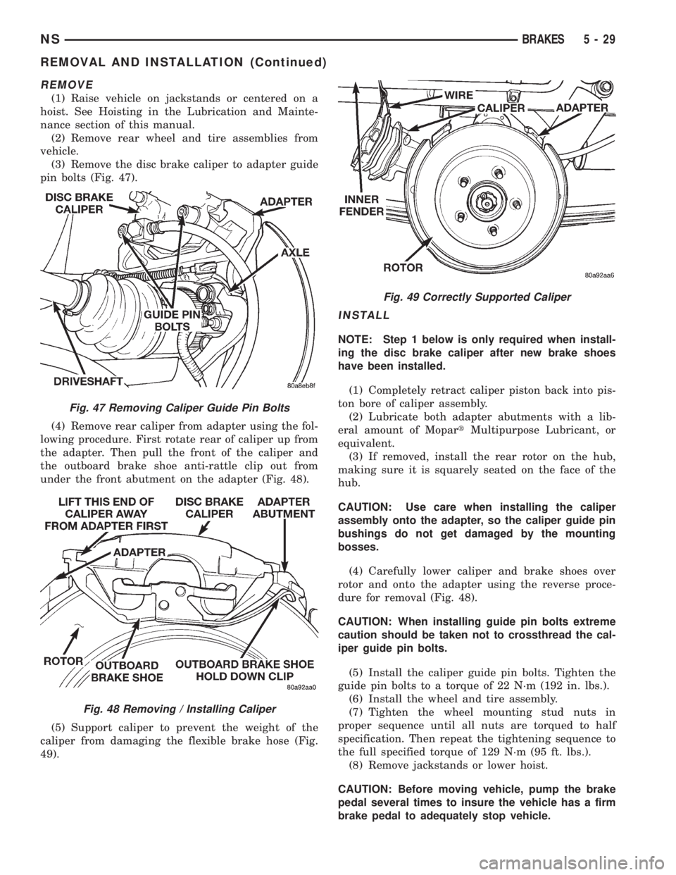
(3) Remove the disc brake caliper to adapter guide
pin bolts (Fig. 47).
(4) Remove rear caliper from adapter using the fol-
lowing procedure. First rotate rear of caliper up from
the adapter. Then pull the front of the caliper and
the outboard brake shoe anti-rattle clip out from
under the front abutment on the adapter (Fig. 48).
(5) Support caliper to prevent the weight of the
caliper from damaging the flexible brake hose (Fig.
49).
INSTALL
NOTE: Step 1 below is only required when install-
ing the disc brake caliper after new brake shoes
have been installed.
(1) Completely retract caliper piston back into pis-
ton bore of caliper assembly.
(2) Lubricate both adapter abutments with a lib-
eral amount of MopartMultipurpose Lubricant, or
equivalent.
(3) If removed, install the rear rotor on the hub,
making sure it is squarely seated on the face of the
hub.
CAUTION: Use care when installing the caliper
assembly onto the adapter, so the caliper guide pin
bushings do not get damaged by the mounting
bosses.
(4) Carefully lower caliper and brake shoes over
rotor and onto the adapter using the reverse proce-
dure for removal (Fig. 48).
CAUTION: When installing guide pin bolts extreme
caution should be taken not to crossthread the cal-
iper guide pin bolts.
(5) Install the caliper guide pin bolts. Tighten the
guide pin bolts to a torque of 22 N´m (192 in. lbs.).
(6) Install the wheel and tire assembly.
(7) Tighten the wheel mounting stud nuts in
proper sequence until all nuts are torqued to half
specification. Then repeat the tightening sequence to
the full specified torque of 129 N´m (95 ft. lbs.).
(8) Remove jackstands or lower hoist.
CAUTION: Before moving vehicle, pump the brake
pedal several times to insure the vehicle has a firm
brake pedal to adequately stop vehicle.
Fig. 47 Removing Caliper Guide Pin Bolts
Fig. 48 Removing / Installing Caliper
Fig. 49 Correctly Supported Caliper
NSBRAKES 5 - 29
REMOVAL AND INSTALLATION (Continued)
Page 113 of 1938
REAR DISC BRAKE SHOES
WARNING: ALTHOUGH FACTORY INSTALLED
BRAKELININGS ARE MADE FROM ASBESTOSFREE MATERIALS, SOME AFTER MARKET BRAKE-
LINING MAY CONTAIN ASBESTOS. THIS SHOULD
BE TAKEN INTO ACCOUNT WHEN SERVICING A
VEHICLE'S BRAKE SYSTEM, WHEN AFTERMARKET
BRAKELININGS MAY HAVE BEEN INSTALLED ON
THE VEHICLE. ALWAYS WEAR A RESPIRATOR
WHEN CLEANING BRAKE COMPONENTS AS
ASBESTOS CAN CAUSE SERIOUS BODILY HARM
SUCH AS ASBESTOSIS AND OR CANCER. NEVER
CLEAN BRAKE COMPONENTS BY USING COM-
PRESSED AIR, USE ONLY A VACUUM CLEANER
SPECIFICALLY DESIGNED FOR THE REMOVAL OF
BRAKE DUST. IF A VACUUM CLEANER IS NOT
AVAILABLE, CLEAN BRAKE PARTS USING ONLY
WATER DAMPENED SHOP TOWELS. DO NOT CRE-
ATE BRAKELINING DUST BY SANDING BRAKE LIN-
INGS WHEN SERVICING A VEHICLE. DISPOSE OF
ALL DUST AND DIRT SUSPECTED OF CONTAINING
ASBESTOS FIBERS USING ONLY SEALED AIR-
TIGHT BAGS OR CONTAINERS. FOLLOW ALL REC-
OMMENDED SAFETY PRACTICES PRESCRIBED BY
THE OCCUPATIONAL SAFETY AND HEALTH ADMIN-
ISTRATION (OSHA) AND THE ENVIRONMENTAL
PROTECTION AGENCY (EPA), FOR HANDLING AND
DISPOSAL OF PRODUCTS CONTAINING ASBES-
TOS.
During service procedures, grease or any other for-
eign material must be kept off brake shoe assem-
blies, and braking surfaces of brake drum and
external surfaces of hub/bearing assembly.
Handling of the braking disc and caliper is to be
done in such a way as to avoid deformation of the
disc and scratching or nicking of brake linings.
If inspection reveals that the square sectioned cal-
iper piston seal is worn or damaged, itMUSTbe
replaced immediately.
During removal and installation of a wheel and
tire assembly, use care not to strike the caliper.
REMOVE
(1) Raise vehicle on jackstands or centered on a
hoist. See Hoisting in the Lubrication and Mainte-
nance section of this manual.
(2) Remove rear wheel and tire assemblies from
vehicle.
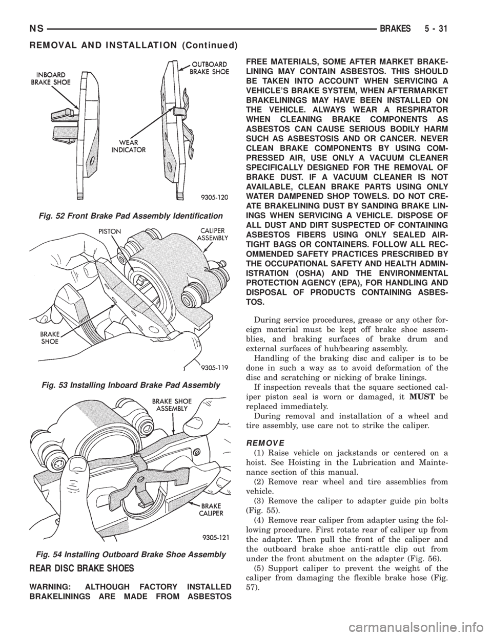
(3) Remove the caliper to adapter guide pin bolts
(Fig. 55).
(4) Remove rear caliper from adapter using the fol-
lowing procedure. First rotate rear of caliper up from
the adapter. Then pull the front of the caliper and
the outboard brake shoe anti-rattle clip out from
under the front abutment on the adapter (Fig. 56).
(5) Support caliper to prevent the weight of the
caliper from damaging the flexible brake hose (Fig.
57).
Fig. 52 Front Brake Pad Assembly Identification
Fig. 53 Installing Inboard Brake Pad Assembly
Fig. 54 Installing Outboard Brake Shoe Assembly
NSBRAKES 5 - 31
REMOVAL AND INSTALLATION (Continued)
Page 114 of 1938
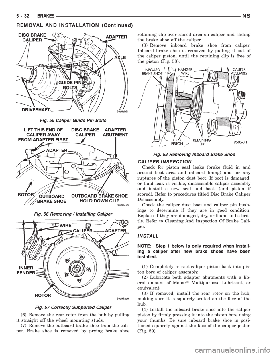
(6) Remove the rear rotor from the hub by pulling
it straight off the wheel mounting studs.
(7) Remove the outboard brake shoe from the cali-
per. Brake shoe is removed by prying brake shoeretaining clip over raised area on caliper and sliding
the brake shoe off the caliper.
(8) Remove inboard brake shoe from caliper.
Inboard brake shoe is removed by pulling it out of
the caliper piston, until the retaining clip is free of
the piston (Fig. 58).
CALIPER INSPECTION
Check for piston seal leaks (brake fluid in and
around boot area and inboard lining) and for any
ruptures of the piston dust boot. If boot is damaged,
or fluid leak is visible, disassemble caliper assembly
and install a new seal and boot, (and piston if
scored). Refer to procedures titled Disc Brake Caliper
Disassembly.
Check the caliper dust boot and caliper pin bush-
ings to determine if they are in good condition.
Replace if they are damaged, dry, or found to be brit-
tle. Refer to Cleaning And Inspection Of Brake Cali-
per.
INSTALL
NOTE: Step 1 below is only required when install-
ing a caliper after new brake shoes have been
installed.
(1) Completely retract caliper piston back into pis-
ton bore of caliper assembly.
(2) Lubricate both adapter abutments with a lib-
eral amount of MopartMultipurpose Lubricant, or
equivalent.
(3) If removed, install the rear rotor on the hub,
making sure it is squarely seated on the face of the
hub.
(4) Install the inboard brake shoe into the caliper
piston by firmly pressing it into the piston bore using
your thumbs. Be sure inboard brake shoe is posi-
tioned squarely against the face of the caliper piston
(Fig. 59).
Fig. 55 Caliper Guide Pin Bolts
Fig. 56 Removing / Installing Caliper
Fig. 57 Correctly Supported Caliper
Fig. 58 Removing Inboard Brake Shoe
5 - 32 BRAKESNS
REMOVAL AND INSTALLATION (Continued)
Page 115 of 1938
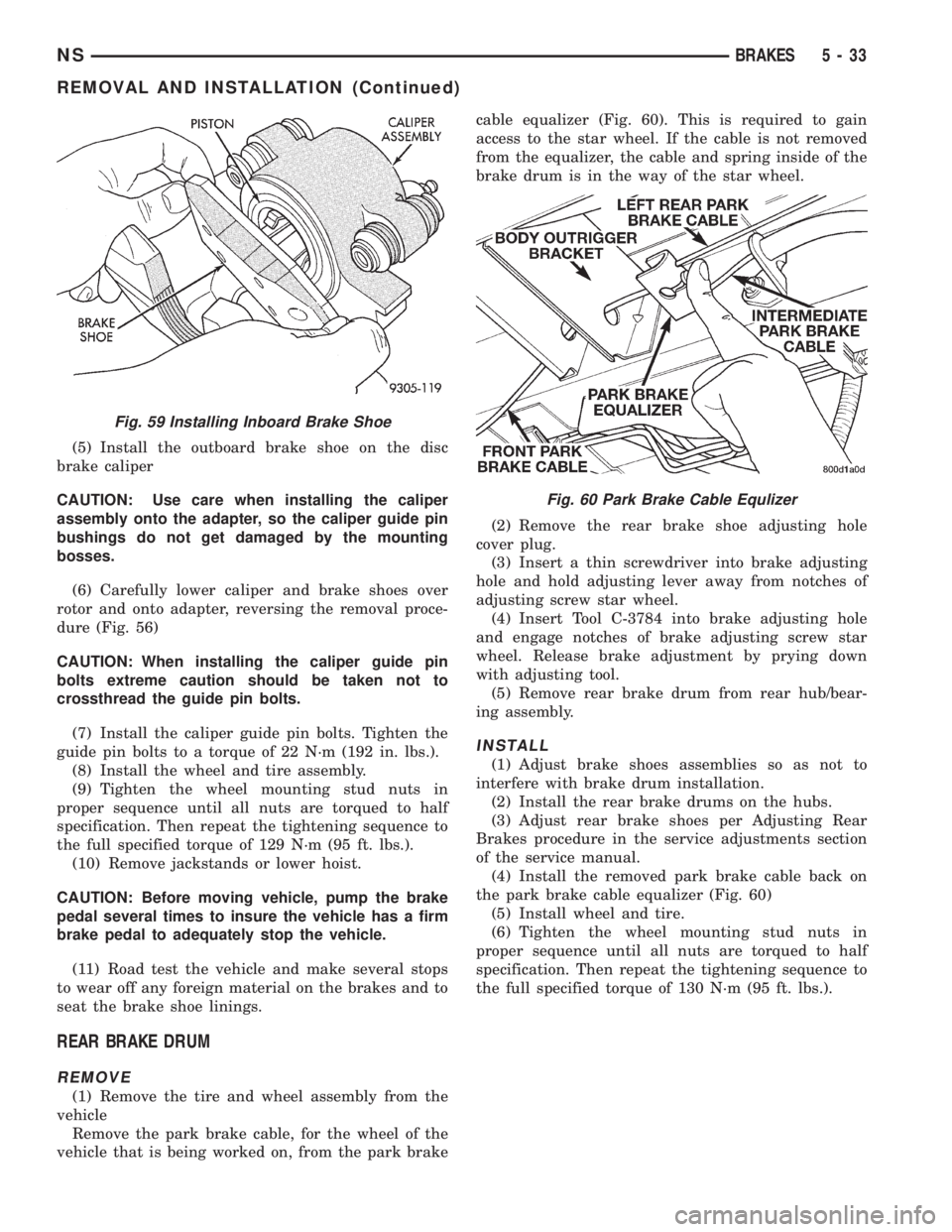
(5) Install the outboard brake shoe on the disc
brake caliper
CAUTION: Use care when installing the caliper
assembly onto the adapter, so the caliper guide pin
bushings do not get damaged by the mounting
bosses.
(6) Carefully lower caliper and brake shoes over
rotor and onto adapter, reversing the removal proce-
dure (Fig. 56)
CAUTION: When installing the caliper guide pin
bolts extreme caution should be taken not to
crossthread the guide pin bolts.
(7) Install the caliper guide pin bolts. Tighten the
guide pin bolts to a torque of 22 N´m (192 in. lbs.).
(8) Install the wheel and tire assembly.
(9) Tighten the wheel mounting stud nuts in
proper sequence until all nuts are torqued to half
specification. Then repeat the tightening sequence to
the full specified torque of 129 N´m (95 ft. lbs.).
(10) Remove jackstands or lower hoist.
CAUTION: Before moving vehicle, pump the brake
pedal several times to insure the vehicle has a firm
brake pedal to adequately stop the vehicle.
(11) Road test the vehicle and make several stops
to wear off any foreign material on the brakes and to
seat the brake shoe linings.
REAR BRAKE DRUM
REMOVE
(1) Remove the tire and wheel assembly from the
vehicle
Remove the park brake cable, for the wheel of the
vehicle that is being worked on, from the park brakecable equalizer (Fig. 60). This is required to gain
access to the star wheel. If the cable is not removed
from the equalizer, the cable and spring inside of the
brake drum is in the way of the star wheel.
(2) Remove the rear brake shoe adjusting hole
cover plug.
(3) Insert a thin screwdriver into brake adjusting
hole and hold adjusting lever away from notches of
adjusting screw star wheel.
(4) Insert Tool C-3784 into brake adjusting hole
and engage notches of brake adjusting screw star
wheel. Release brake adjustment by prying down
with adjusting tool.
(5) Remove rear brake drum from rear hub/bear-
ing assembly.
INSTALL
(1) Adjust brake shoes assemblies so as not to
interfere with brake drum installation.
(2) Install the rear brake drums on the hubs.
(3) Adjust rear brake shoes per Adjusting Rear
Brakes procedure in the service adjustments section
of the service manual.
(4) Install the removed park brake cable back on
the park brake cable equalizer (Fig. 60)
(5) Install wheel and tire.
(6) Tighten the wheel mounting stud nuts in
proper sequence until all nuts are torqued to half
specification. Then repeat the tightening sequence to
the full specified torque of 130 N´m (95 ft. lbs.).
Fig. 59 Installing Inboard Brake Shoe
Fig. 60 Park Brake Cable Equlizer
NSBRAKES 5 - 33
REMOVAL AND INSTALLATION (Continued)
Page 119 of 1938
CAUTION: When installing the tension clip on the
automatic adjuster, it must be located on only the
threaded area of the adjuster assembly (Fig. 66). If
it is located on a non-threaded area of the adjuster,
the function of the automatic adjuster will be
affected.
(7) Install the tension clip (Fig. 66) attaching the
upper return spring to the automatic adjuster assem-
bly.
(8) Install the brake shoe to brake shoe lower
return springs on the brake shoes (Fig. 64) and (Fig.
65).
(9) Install automatic adjustment lever on the lead-
ing brake shoe of the rear brake assembly (Fig. 63).
(10) Install the actuating spring on the automatic
adjustment lever and leading brake shoe assembly
(Fig. 62).
(11) Verify that the automatic adjuster lever has
positive contact with the star wheel on the automatic
adjuster assembly.
(12) When all components of both rear brake
assemblies are correctly and fully installed, remove
the locking pliers from the front park brake cable.
(13) Adjust brake shoes assemblies so as not to
interfere with brake drum installation.
(14) Install the rear brake drums on the hubs.
(15) Adjust rear brake shoes per Adjusting Rear
Brakes procedure in the service adjustments section
of the service manual.
(16) Install the wheel and tire assembly.
(17) Push the park brake pedal to the floor once
and release pedal. This will automatically remove the
slack from and correctly adjust the park brake
cables.
(18) Tighten the wheel mounting stud nuts in
proper sequence until all nuts are torqued to half
specification. Then repeat the tightening sequence to
the full specified torque of 130 N´m (95 ft. lbs.).
(19) Road test vehicle. The automatic adjuster will
continue the brake adjustment during the road test
of the vehicle.
BRAKE SUPPORT PLATE (REAR DRUM BRAKES)
REMOVE
(1) Raise vehicle on jackstands or centered on a
frame contact type hoist. See Hoisting in the Lubri-
cation and Maintenance section of this service man-
ual for required lifting procedure.
(2) Remove wheel and tire.
(3) Remove brake drum from hub/bearing.
(4) Remove brake shoes from brake support plate.
Refer to Rear Brake Shoe Removal in the removal
and installation section in this group of the service
manual for the required procedure.(5) Disconnect the park brake cable from the park
brake actuation lever.
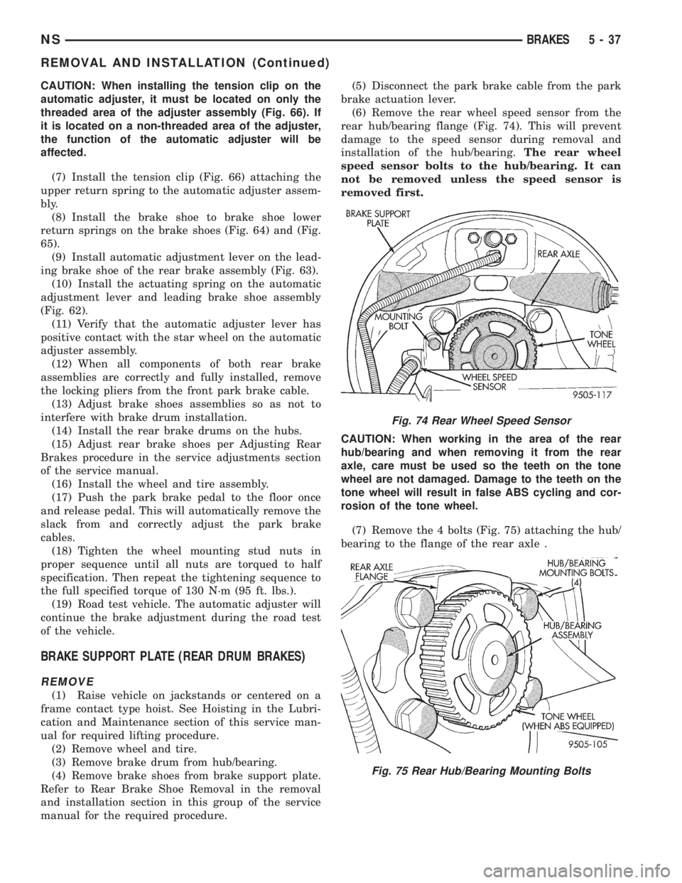
(6) Remove the rear wheel speed sensor from the
rear hub/bearing flange (Fig. 74). This will prevent
damage to the speed sensor during removal and
installation of the hub/bearing.The rear wheel
speed sensor bolts to the hub/bearing. It can
not be removed unless the speed sensor is
removed first.
CAUTION: When working in the area of the rear
hub/bearing and when removing it from the rear
axle, care must be used so the teeth on the tone
wheel are not damaged. Damage to the teeth on the
tone wheel will result in false ABS cycling and cor-
rosion of the tone wheel.
(7) Remove the 4 bolts (Fig. 75) attaching the hub/
bearing to the flange of the rear axle .
Fig. 74 Rear Wheel Speed Sensor
Fig. 75 Rear Hub/Bearing Mounting Bolts
NSBRAKES 5 - 37
REMOVAL AND INSTALLATION (Continued)
Page 120 of 1938
CAUTION: Corrosion may occur between the hub/
bearing and the axle. If this occurs the hub/bearing
will be difficult to remove from the axle. If the hub/
bearing will not come out of the axle by pulling on
it by hand, do not pound on the hub/bearing to
remove it from the axle. Pounding on the hub/bear-
ing to remove it from the axle will damage the hub/
bearing. This damage will result in noise or failure
of the bearing.
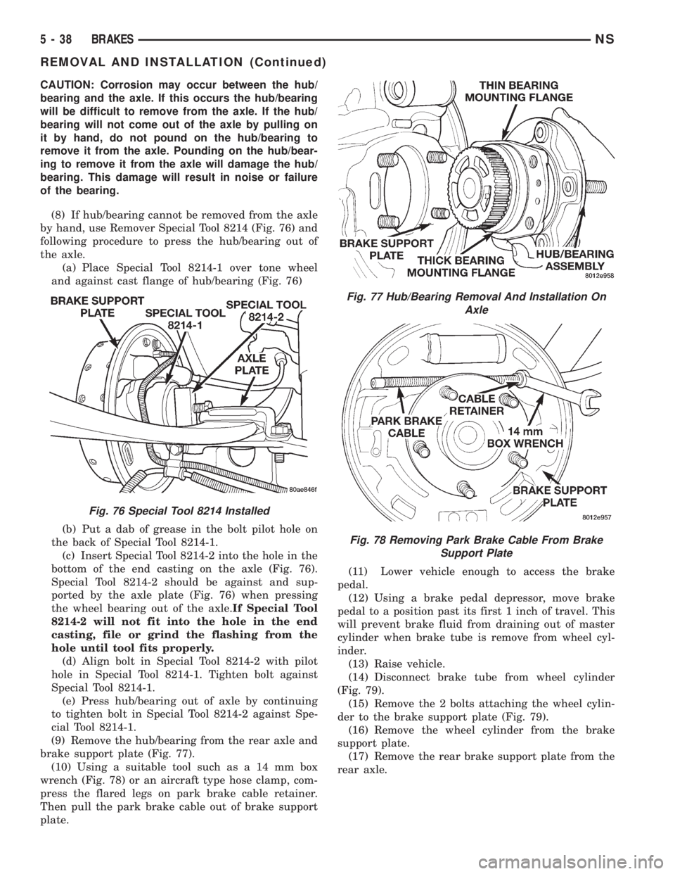
(8) If hub/bearing cannot be removed from the axle
by hand, use Remover Special Tool 8214 (Fig. 76) and
following procedure to press the hub/bearing out of
the axle.
(a) Place Special Tool 8214-1 over tone wheel
and against cast flange of hub/bearing (Fig. 76)
(b) Put a dab of grease in the bolt pilot hole on
the back of Special Tool 8214-1.
(c) Insert Special Tool 8214-2 into the hole in the
bottom of the end casting on the axle (Fig. 76).
Special Tool 8214-2 should be against and sup-
ported by the axle plate (Fig. 76) when pressing
the wheel bearing out of the axle.If Special Tool
8214-2 will not fit into the hole in the end
casting, file or grind the flashing from the
hole until tool fits properly.
(d) Align bolt in Special Tool 8214-2 with pilot
hole in Special Tool 8214-1. Tighten bolt against
Special Tool 8214-1.
(e) Press hub/bearing out of axle by continuing
to tighten bolt in Special Tool 8214-2 against Spe-
cial Tool 8214-1.
(9) Remove the hub/bearing from the rear axle and
brake support plate (Fig. 77).
(10) Using a suitable tool such as a 14 mm box
wrench (Fig. 78) or an aircraft type hose clamp, com-
press the flared legs on park brake cable retainer.
Then pull the park brake cable out of brake support
plate.(11) Lower vehicle enough to access the brake
pedal.
(12) Using a brake pedal depressor, move brake
pedal to a position past its first 1 inch of travel. This
will prevent brake fluid from draining out of master
cylinder when brake tube is remove from wheel cyl-
inder.
(13) Raise vehicle.
(14) Disconnect brake tube from wheel cylinder
(Fig. 79).
(15) Remove the 2 bolts attaching the wheel cylin-
der to the brake support plate (Fig. 79).
(16) Remove the wheel cylinder from the brake
support plate.
(17) Remove the rear brake support plate from the
rear axle.
Fig. 76 Special Tool 8214 Installed
Fig. 77 Hub/Bearing Removal And Installation On
Axle
Fig. 78 Removing Park Brake Cable From Brake
Support Plate
5 - 38 BRAKESNS
REMOVAL AND INSTALLATION (Continued)