wheel bolts CHRYSLER VOYAGER 1996 Workshop Manual
[x] Cancel search | Manufacturer: CHRYSLER, Model Year: 1996, Model line: VOYAGER, Model: CHRYSLER VOYAGER 1996Pages: 1938, PDF Size: 55.84 MB
Page 165 of 1938
BRAKE ACTUATION SYSTEM
ACTUATION:
Vacuum Operated Power Brakes.........Standard
Hydraulic System...........Dual-Diagonally Split
Antilock Brake Sytem (Teves Mark-20)...........
MASTER CYLINDER ASSEMBLY:
Supplier..............................Bosch
Type For Non-ABSAnd
ABS Brakes. . . .Conventional Compensating Port
Type For ABS Brakes
With Traction Control . . .Dual Center Port Design
Body Material...............Anodized Aluminum
Reservoir Material................Polypropelene
MASTER CYLINDER BORE /
STROKE AND SPLIT:
ABS W/Disc/Drum Brakes......23.8 mm x 36 mm
(.937 in. x 1.47 in.)
AWD W/Disc/Disc Brakes........25.4 mm x 39 mm
(1.00 in. x 1.50 in.)
Displacement Split.....................50/50
MASTER CYLINDER FLUID OUTLET PORTS:
Non-ABS And ABS . . .Primary 7/16±24 Secondary 7/
16±24
ABS With Traction Control.......Primary M12 x 1
Secondary M12 x 1
Outlet Fitting Type Non-ABS
AndABS...........Double Wall Inverted Flare
Outlet Fitting Type ABS With
Traction Control...................ISO Flare
ABS HYDRAULIC CONTROL UNIT:
Hydraulic Tube Fitting Type............ISO Flare
BOOSTER:
Make/Type.................Bosch Vacuum Assist
Mounting Studs.....................M8x1.25
Type .........................270 ZLT RSMV
Boost At 20 inches Of
Manifold Vacuum...........3800 N´m (850 lbs.)
PROPORTIONING VALVE:
Material...........................Aluminum
Function....................Hydraulic Pressure
Proportioning To Rear Brakes
BRAKE PEDAL
Pedal Ratio.............................3.36
BRAKE FASTENER TORQUE SPECIFICATIONS
DESCRIPTION TORQUE
BRAKE TUBES:
Tube Nuts To Fittings And
Components..............17N´m(145 in. lbs.)
BRAKE HOSE:
To Caliper Banjo Bolt..........48N´m(35ft.lbs.)
Intermediate Bracket.........12N´m(105 in. lbs.)
MASTER CYLINDER:
To Vacuum Booster
Mounting Nut............25N´m(225 in. lbs.)
FIXED PROPORTIONING VALVE:
To Frame Rail Attaching
Bolts....................14N´m(125 in. lbs.)
HEIGHT SENSING PROPORTIONING VALVE:
To Mounting Bracket
Attaching Bolts...........23N´m(200 in. lbs.)
Actuator Assembly
Adjustment Nut.............5N´m(45in.lbs.)
Mounting Bracket To Frame
Rail Bolts................17N´m(150 in. lbs.)
JUNCTION BLOCK (NON-ABS BRAKES)
To Suspension Cradle
Mounting Bolt............28N´m(250 in. lbs.)
VACUUM BOOSTER:
To Dash Panel Mounting
Nuts....................28N´m(250 in. lbs.)
REAR WHEEL CYLINDER:
To Support Plate Mounting
Bolts.....................8N´m(75in.lbs.)
Bleeder Screw...............10N´m(80in.lbs.)
BRAKE SUPPORT PLATE:
To Rear Axle Mounting Bolts . . .130 N´m (95 ft. lbs.)
DISC BRAKE CALIPER:
Guide Pin Bolts..............41N´m(30ft.lbs.)
Bleeder Screw..............15N´m(125 in. lbs.)
ABS HYDRAULIC CONTROL UNIT:
Mounting Bracket To
Suspension Cradle Bolts.....28N´m(250 in. lbs.)
To Mounting Bracket Isolator
Attaching Bolts............11N´m(97in.lbs.)
CAB To HCU Mounting Screws . . .2 N´m (17 in. lbs.)
WHEEL SPEED SENSOR:
To Axle Or Steering Knuckle
Mounting Bolt............12N´m(105 in. lbs.)
PARKING BRAKE:
Pedal Assembly Mounting
Bolts....................28N´m(250 in. lbs.)
REAR HUB AND BEARING:
To Axle Mounting Bolts........129 N´m (95 ft. lbs.)
WHEEL:
Stud Lug Nut........115±156 N´m (84-115 ft. lbs.)
NSBRAKES 5 - 83
SPECIFICATIONS (Continued)
Page 188 of 1938

(7) Remove the wheel speed sensor cable grommets
from the retaining bracket (Fig. 37).(8) Remove front wheel speed sensor assembly
from the vehicle.
INSTALL
CAUTION: Proper installation of wheel speed sen-
sor cables is critical to continued system operation.
Be sure that cables are installed in retainers. Fail-
ure to install cables in retainers as shown in this
section may result in contact with moving parts
and/or over extension of cables, resulting in an
open circuit.
(1) Connect the front wheel speed sensor cable to
the vehicle wiring harness connector (Fig. 35). Be
sure speed sensor cable connector is fully seated and
locked into vehicle wiring harness connector, then
insert cable and grommet into hole in strut tower
(Fig. 35).
CAUTION: When installing channel bracket, do not
pinch the speed sensor cable under the channel
bracket.
(2) Install the channel bracket and grommet
retainer on the frame rail (Fig. 34).
(3) Install the 2 bolts (Fig. 34) attaching the chan-
nel bracket to frame. Tighten the 2 attaching bolts to
a torque of 11 N´m (95 in. lbs.).
(4) Insert speed sensor cable grommets into inter-
mediate bracket on strut (Fig. 37). Route cable from
strut to steering knuckle on the rearward side of the
stabilizer bar link.
(5) Install the wheel speed sensor to steering
knuckle attaching bolt (Fig. 36). Tighten the speed
sensor attaching bolt to a torque of 12 N´m (105 in.
lbs.)
(6) Check the air gap between the face of the
wheel speed sensor and the top surface of the tone-
wheel. Air gap must be less then the maximum
allowable tolerance of 1.2 mm (.047 in.).
(7) Install the wheel and tire assembly on vehicle.
(8) Road test vehicle to ensure proper operation of
the base and ABS brake systems.
WHEEL SPEED SENSOR (REAR FWD)
REMOVE
(1) Raise vehicle on jack stands or centered on a
frame contact type hoist. See Hoisting in the Lubri-
cation and Maintenance section of this manual, for
the required lifting procedure to be used for this
vehicle.
(2) Remove the tire and wheel assembly from the
vehicle.
Fig. 35 Speed Sensor Cable To Vehicle Wiring
Harness
Fig. 36 Front Wheel Speed Sensor Attaching Bolt
Fig. 37 Front Wheel Speed Sensor Cable Routing
5 - 106 BRAKESNS
REMOVAL AND INSTALLATION (Continued)
Page 192 of 1938

(2) Install the wheel speed sensor head attaching
bolt (Fig. 46). Tighten the attaching bolt to a torque
12 N´m (105 in. lbs.)
(3) Check the air gap between the face of the
wheel speed sensor and the top surface of the tone-
wheel. Air gap must be less then the maximum
allowable tolerance of 1.2 mm (.047 in.).
(4) Install the routing brackets attaching the speed
sensor cable and brake tube to the rear axle (Fig.
45).The rear wheel speed sensor cable should
be routed under the rear brake tube (Fig. 45).
CAUTION: When installing rear wheel speed sen-
sor cable in the routing clips on rear brake flex
hose, be sure not to damage the routing clips.
Routing clips are molded onto the hose and will
require replacement of the brake flex hose if dam-
aged during installation of the wheel speed sensor
cable.
(5) Install speed sensor cable into routing clips on
rear brake flex hose (Fig. 44).
CAUTION: The wheel speed sensor cable connec-
tors for the left and right rear wheel speed sensors
are keyed differently. Therefore, when connecting a
wheel speed sensor cable to the vehicle wiring har-
ness, do not force the connectors together. If the
connectors are forced together, damage to the con-
nectors will occur.
(6) Plug speed sensor cable connector into vehicle
wiring harness (Fig. 43).Be sure speed sensor
cable connector is fully seated and locked into
vehicle wiring harness connector.
(7) Install the speed sensor cable grommet into the
body, being sure the grommet is fully seated into the
body hole.
(8) Install the tire and wheel assembly on vehicle.
(9) Road test vehicle to ensure proper operation of
the base and ABS braking systems.
TONE WHEEL (REAR FWD)
REMOVE
(1) Raise vehicle on jackstands or centered on a
frame contact type hoist. See Hoisting in the Lubri-
cation and Maintenance section of this service man-
ual for required lifting procedure.
(2) Remove the wheel and tire assembly.
(3) Remove rear brake drum from the hub/bearing
assembly.
(4) Remove the rear wheel speed sensor from the
rear hub/bearing flange (Fig. 47). This will prevent
damage to the speed sensor during removal and
installation of the hub/bearing assembly.(5) Remove the 4 bolts (Fig. 48) attaching the hub/
bearing assembly to the flange of the rear axle.
(6) Remove the hub/bearing assembly from the
rear axle and brake support plate (Fig. 49).
Fig. 47 Rear Wheel Speed Sensor
Fig. 48 Rear Hub/Bearing Mounting Bolts
Fig. 49 Removing Rear Hub/Bearing From Axle
5 - 110 BRAKESNS
REMOVAL AND INSTALLATION (Continued)
Page 193 of 1938
(7) Install wheel lug nuts on 3 of the wheel mount-
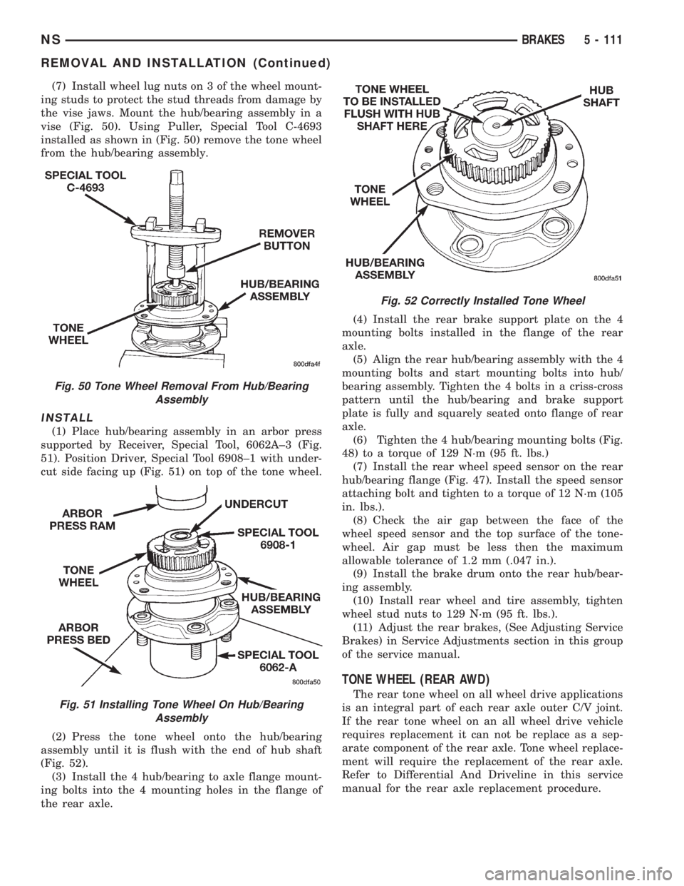
ing studs to protect the stud threads from damage by
the vise jaws. Mount the hub/bearing assembly in a
vise (Fig. 50). Using Puller, Special Tool C-4693
installed as shown in (Fig. 50) remove the tone wheel
from the hub/bearing assembly.
INSTALL
(1) Place hub/bearing assembly in an arbor press
supported by Receiver, Special Tool, 6062A±3 (Fig.
51). Position Driver, Special Tool 6908±1 with under-
cut side facing up (Fig. 51) on top of the tone wheel.
(2) Press the tone wheel onto the hub/bearing
assembly until it is flush with the end of hub shaft
(Fig. 52).
(3) Install the 4 hub/bearing to axle flange mount-
ing bolts into the 4 mounting holes in the flange of
the rear axle.(4) Install the rear brake support plate on the 4
mounting bolts installed in the flange of the rear
axle.
(5) Align the rear hub/bearing assembly with the 4
mounting bolts and start mounting bolts into hub/
bearing assembly. Tighten the 4 bolts in a criss-cross
pattern until the hub/bearing and brake support
plate is fully and squarely seated onto flange of rear
axle.
(6) Tighten the 4 hub/bearing mounting bolts (Fig.
48) to a torque of 129 N´m (95 ft. lbs.)
(7) Install the rear wheel speed sensor on the rear
hub/bearing flange (Fig. 47). Install the speed sensor
attaching bolt and tighten to a torque of 12 N´m (105
in. lbs.).
(8) Check the air gap between the face of the
wheel speed sensor and the top surface of the tone-
wheel. Air gap must be less then the maximum
allowable tolerance of 1.2 mm (.047 in.).
(9) Install the brake drum onto the rear hub/bear-
ing assembly.
(10) Install rear wheel and tire assembly, tighten
wheel stud nuts to 129 N´m (95 ft. lbs.).
(11) Adjust the rear brakes, (See Adjusting Service
Brakes) in Service Adjustments section in this group
of the service manual.
TONE WHEEL (REAR AWD)
The rear tone wheel on all wheel drive applications
is an integral part of each rear axle outer C/V joint.
If the rear tone wheel on an all wheel drive vehicle
requires replacement it can not be replace as a sep-
arate component of the rear axle. Tone wheel replace-
ment will require the replacement of the rear axle.
Refer to Differential And Driveline in this service
manual for the rear axle replacement procedure.
Fig. 50 Tone Wheel Removal From Hub/Bearing
Assembly
Fig. 51 Installing Tone Wheel On Hub/Bearing
Assembly
Fig. 52 Correctly Installed Tone Wheel
NSBRAKES 5 - 111
REMOVAL AND INSTALLATION (Continued)
Page 194 of 1938
SPECIFICATIONS
SPEED SENSOR TONE WHEEL RUNOUT
The total indicator runout allowed for both the
front and rear tone wheel measured using a dial indi-
cator is 0.15 mm (.006 in.).
WHEEL SPEED SENSOR TO TONE WHEEL
CLEARANCE
FRONT WHEEL
Minimum Clearance .35mm (.014 in.)
Maxamum Clearance 1.2 mm (.047 in.)
REAR WHEEL
Minimum Clearance .40mm (.016 in.)
Maxamum Clearance 1.2 mm (.047 in.)
BRAKE FASTENER TORQUE SPECIFICATIONS
DESCRIPTION TORQUE
BRAKE TUBES:
Tube Nuts To Fittings And
Components..............17N´m(145 in. lbs.)
BRAKE HOSE:
To Caliper Banjo Bolt..........48N´m(35ft.lbs.)
Intermediate Bracket.........12N´m(105 in. lbs.)
MASTER CYLINDER:
To Vacuum Booster
Mounting Nut............25N´m(225 in. lbs.)
FIXED PROPORTIONING VALVE:
To Frame Rail Attaching
Bolts....................14N´m(125 in. lbs.)
HEIGHT SENSING PROPORTIONING VALVE:
To Mounting Bracket
Attaching Bolts...........23N´m(200 in. lbs.)
Actuator Assembly
Adjustment Nut.............5N´m(45in.lbs.)
Mounting Bracket To
Frame Rail Bolts..........17N´m(150 in. lbs.)
JUNCTION BLOCK (NON-ABS BRAKES)
To Suspension Cradle
Mounting Bolt............28N´m(250 in. lbs.)
VACUUM BOOSTER:
To Dash Panel Mounting
Nuts....................28N´m(250 in. lbs.)DESCRIPTION TORQUE
REAR WHEEL CYLINDER:
To Support Plate Mounting
Bolts.....................8N´m(75in.lbs.)
Bleeder Screw...............10N´m(80in.lbs.)
BRAKE SUPPORT PLATE:
To Rear Axle Mounting Bolts . . .130 N´m (95 ft. lbs.)
DISC BRAKE CALIPER:
Guide Pin Bolts..............41N´m(30ft.lbs.)
Bleeder Screw..............15N´m(125 in. lbs.)
ABS HYDRAULIC CONTROL UNIT:
Mounting Bracket To
Suspension Cradle Bolts.....28N´m(250 in. lbs.)
To Mounting Bracket Isolator
Attaching Bolts............11N´m(97in.lbs.)
CAB To HCU Mounting Screws . . .2 N´m (17 in. lbs.)
WHEEL SPEED SENSOR:
To Axle Or Steering Knuckle
Mounting Bolt............12N´m(105 in. lbs.)
PARKING BRAKE:
Pedal Assembly Mounting
Bolts....................28N´m(250 in. lbs.)
REAR HUB AND BEARING:
To Axle Mounting Bolts........129 N´m (95 ft. lbs.)
WHEEL:
Stud Lug Nut........115±156 N´m (84-115 ft. lbs.)
5 - 112 BRAKESNS
Page 196 of 1938
Upon application of the brake pedal, the lever
should move down, turning the star wheel. A definite
rotation of the star wheel should be seen if the auto-
matic adjuster is working properly. If no rotation of
the star wheel is observed when the pedal is consec-
utively pressed and released, the respective drum
will have to be removed and the adjuster serviced.
MASTER CYLINDER FLUID LEVEL CHECK
The master cylinder used in this vehicle has the
same fluid level markings as the master cylinders
used in other brake systems on the side of the fluid
resevoir. Refer to the Master Cylinder Fluid Level
Check in the Diagnosis and Testing section of group
5 for more information
REMOVAL AND INSTALLATION
FRONT PARK BRAKE CABLE AND LEVER
ASSEMBLY-RHD&LHD VEHICLES
REMOVE
(1) Raise vehicle on jackstands or centered on a
hoist. See Hoisting in the Lubrication and Mainte-
nance group of this service manual.
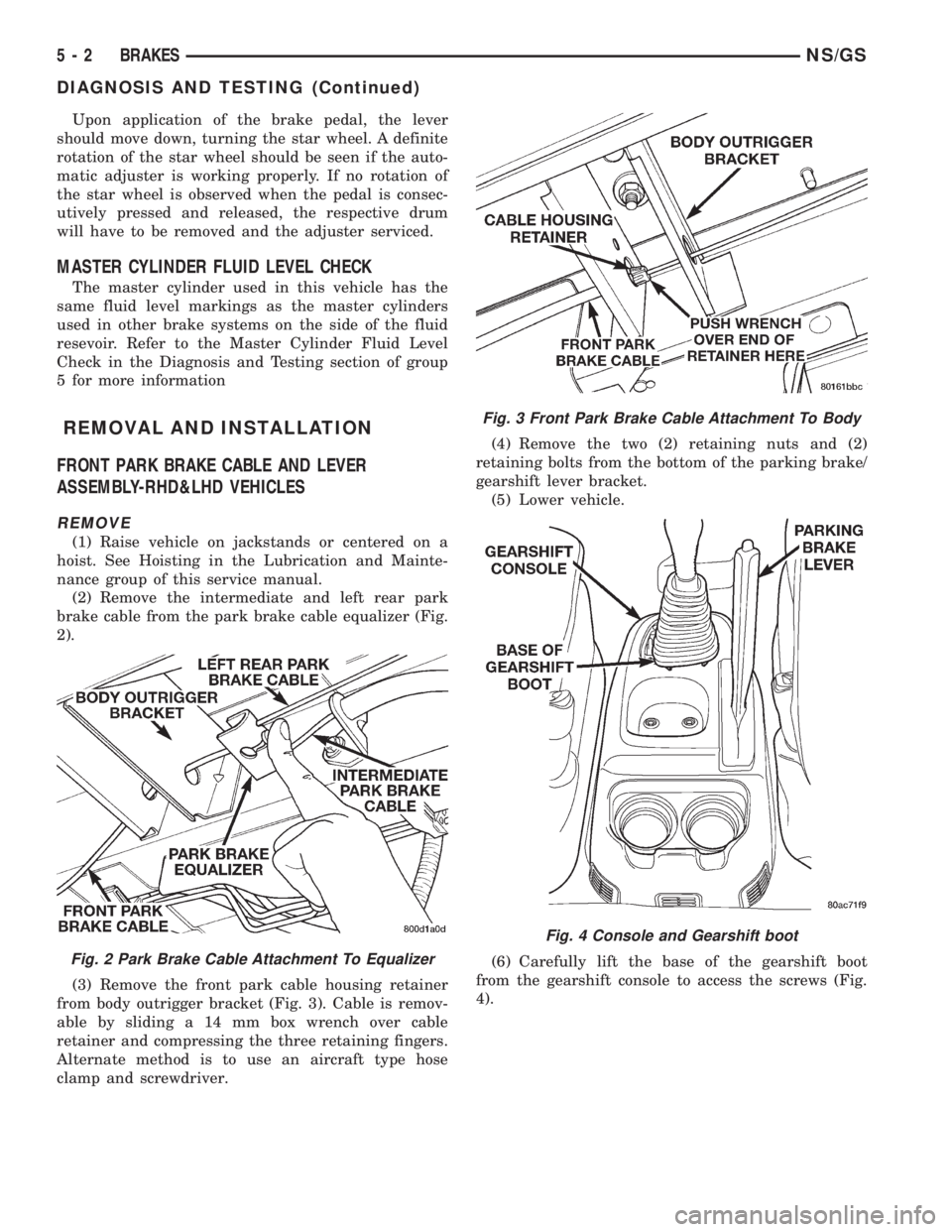
(2) Remove the intermediate and left rear park
brake cable from the park brake cable equalizer (Fig.
2).
(3) Remove the front park cable housing retainer
from body outrigger bracket (Fig. 3). Cable is remov-
able by sliding a 14 mm box wrench over cable
retainer and compressing the three retaining fingers.
Alternate method is to use an aircraft type hose
clamp and screwdriver.(4) Remove the two (2) retaining nuts and (2)
retaining bolts from the bottom of the parking brake/
gearshift lever bracket.
(5) Lower vehicle.
(6) Carefully lift the base of the gearshift boot
from the gearshift console to access the screws (Fig.
4).
Fig. 2 Park Brake Cable Attachment To Equalizer
Fig. 3 Front Park Brake Cable Attachment To Body
Fig. 4 Console and Gearshift boot
5 - 2 BRAKESNS/GS
DIAGNOSIS AND TESTING (Continued)
Page 205 of 1938
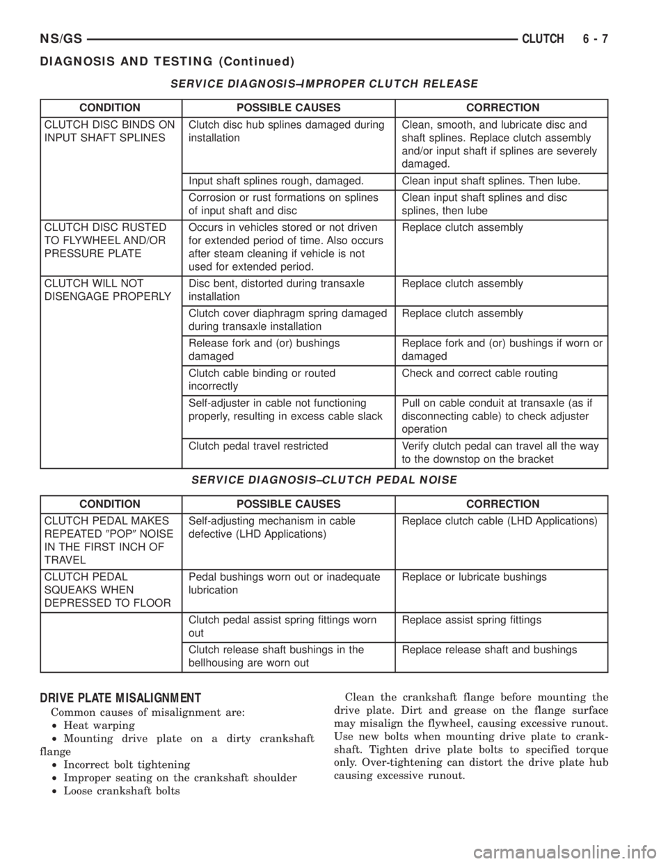
SERVICE DIAGNOSIS±IMPROPER CLUTCH RELEASE
CONDITION POSSIBLE CAUSES CORRECTION
CLUTCH DISC BINDS ON
INPUT SHAFT SPLINESClutch disc hub splines damaged during
installationClean, smooth, and lubricate disc and
shaft splines. Replace clutch assembly
and/or input shaft if splines are severely
damaged.
Input shaft splines rough, damaged. Clean input shaft splines. Then lube.
Corrosion or rust formations on splines
of input shaft and discClean input shaft splines and disc
splines, then lube
CLUTCH DISC RUSTED
TO FLYWHEEL AND/OR
PRESSURE PLATEOccurs in vehicles stored or not driven
for extended period of time. Also occurs
after steam cleaning if vehicle is not
used for extended period.Replace clutch assembly
CLUTCH WILL NOT
DISENGAGE PROPERLYDisc bent, distorted during transaxle
installationReplace clutch assembly
Clutch cover diaphragm spring damaged
during transaxle installationReplace clutch assembly
Release fork and (or) bushings
damagedReplace fork and (or) bushings if worn or
damaged
Clutch cable binding or routed
incorrectlyCheck and correct cable routing
Self-adjuster in cable not functioning
properly, resulting in excess cable slackPull on cable conduit at transaxle (as if
disconnecting cable) to check adjuster
operation
Clutch pedal travel restricted Verify clutch pedal can travel all the way
to the downstop on the bracket
SERVICE DIAGNOSIS±CLUTCH PEDAL NOISE
CONDITION POSSIBLE CAUSES CORRECTION
CLUTCH PEDAL MAKES
REPEATED9POP9NOISE
IN THE FIRST INCH OF
TRAVELSelf-adjusting mechanism in cable
defective (LHD Applications)Replace clutch cable (LHD Applications)
CLUTCH PEDAL
SQUEAKS WHEN
DEPRESSED TO FLOORPedal bushings worn out or inadequate
lubricationReplace or lubricate bushings
Clutch pedal assist spring fittings worn
outReplace assist spring fittings
Clutch release shaft bushings in the
bellhousing are worn outReplace release shaft and bushings
DRIVE PLATE MISALIGNMENT
Common causes of misalignment are:
²Heat warping
²Mounting drive plate on a dirty crankshaft
flange
²Incorrect bolt tightening
²Improper seating on the crankshaft shoulder
²Loose crankshaft boltsClean the crankshaft flange before mounting the
drive plate. Dirt and grease on the flange surface
may misalign the flywheel, causing excessive runout.
Use new bolts when mounting drive plate to crank-
shaft. Tighten drive plate bolts to specified torque
only. Over-tightening can distort the drive plate hub
causing excessive runout.
NS/GSCLUTCH 6 - 7
DIAGNOSIS AND TESTING (Continued)
Page 211 of 1938
INSTALLATION
1. Position the slave cylinder assembly to the tran-
saxle deck and secure with the nut and washer
assemblies (2) and tighten to specifications (Fig. 14).
2. Make sure the slave cylinder pushrod is prop-
erly seated in the cup end of the clutch release lever.
3. Connect the quick connect coupling. Refer to the
ªQuick Connect Couplingº removal and installation
procedure in this section.
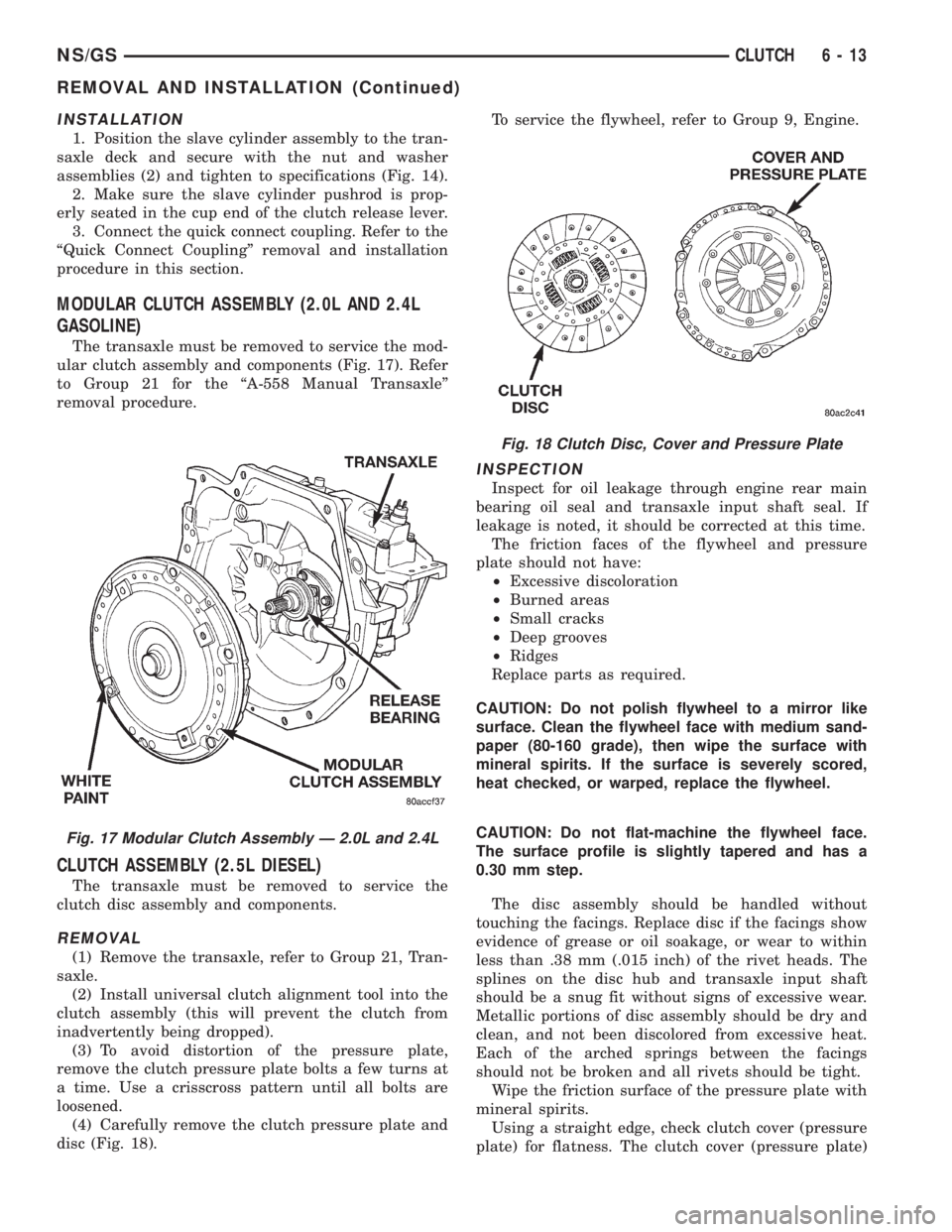
MODULAR CLUTCH ASSEMBLY (2.0L AND 2.4L
GASOLINE)
The transaxle must be removed to service the mod-
ular clutch assembly and components (Fig. 17). Refer
to Group 21 for the ªA-558 Manual Transaxleº
removal procedure.
CLUTCH ASSEMBLY (2.5L DIESEL)
The transaxle must be removed to service the
clutch disc assembly and components.
REMOVAL
(1) Remove the transaxle, refer to Group 21, Tran-
saxle.
(2) Install universal clutch alignment tool into the
clutch assembly (this will prevent the clutch from
inadvertently being dropped).
(3) To avoid distortion of the pressure plate,
remove the clutch pressure plate bolts a few turns at
a time. Use a crisscross pattern until all bolts are
loosened.
(4) Carefully remove the clutch pressure plate and
disc (Fig. 18).To service the flywheel, refer to Group 9, Engine.
INSPECTION
Inspect for oil leakage through engine rear main
bearing oil seal and transaxle input shaft seal. If
leakage is noted, it should be corrected at this time.
The friction faces of the flywheel and pressure
plate should not have:
²Excessive discoloration
²Burned areas
²Small cracks
²Deep grooves
²Ridges
Replace parts as required.
CAUTION: Do not polish flywheel to a mirror like
surface. Clean the flywheel face with medium sand-
paper (80-160 grade), then wipe the surface with
mineral spirits. If the surface is severely scored,
heat checked, or warped, replace the flywheel.
CAUTION: Do not flat-machine the flywheel face.
The surface profile is slightly tapered and has a
0.30 mm step.
The disc assembly should be handled without
touching the facings. Replace disc if the facings show
evidence of grease or oil soakage, or wear to within
less than .38 mm (.015 inch) of the rivet heads. The
splines on the disc hub and transaxle input shaft
should be a snug fit without signs of excessive wear.
Metallic portions of disc assembly should be dry and
clean, and not been discolored from excessive heat.
Each of the arched springs between the facings
should not be broken and all rivets should be tight.
Wipe the friction surface of the pressure plate with
mineral spirits.
Using a straight edge, check clutch cover (pressure
plate) for flatness. The clutch cover (pressure plate)
Fig. 17 Modular Clutch Assembly Ð 2.0L and 2.4L
Fig. 18 Clutch Disc, Cover and Pressure Plate
NS/GSCLUTCH 6 - 13
REMOVAL AND INSTALLATION (Continued)
Page 212 of 1938
friction area should be slightly concave, with the
inner diameter 0.02 mm to 0.1 mm (.0008 in. to .0039
in.) below the outer diameter. It should also be free
from discoloration, burned areas, cracks, grooves, or
ridges.
Using a surface plate, test cover for flatness. All
sections around attaching bolt holes should be in con-
tact with surface plate within .015 inch.
The cover should be a snug fit on flywheel dowels.
If the clutch assembly does not meet these require-
ments, it should be replaced.
INSTALLATION
(1) Position the clutch and pressure plate onto the
flywheel.
(2) Insert the universal clutch alignment tool into
the clutch disc.
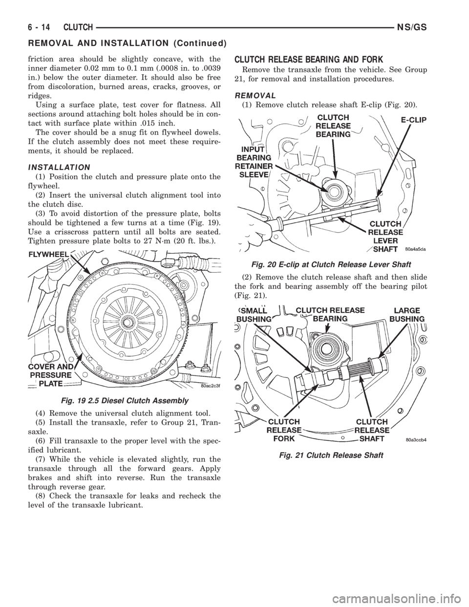
(3) To avoid distortion of the pressure plate, bolts
should be tightened a few turns at a time (Fig. 19).
Use a crisscross pattern until all bolts are seated.
Tighten pressure plate bolts to 27 N´m (20 ft. lbs.).
(4) Remove the universal clutch alignment tool.
(5) Install the transaxle, refer to Group 21, Tran-
saxle.
(6) Fill transaxle to the proper level with the spec-
ified lubricant.
(7) While the vehicle is elevated slightly, run the
transaxle through all the forward gears. Apply
brakes and shift into reverse. Run the transaxle
through reverse gear.
(8) Check the transaxle for leaks and recheck the
level of the transaxle lubricant.
CLUTCH RELEASE BEARING AND FORK
Remove the transaxle from the vehicle. See Group
21, for removal and installation procedures.
REMOVAL
(1) Remove clutch release shaft E-clip (Fig. 20).
(2) Remove the clutch release shaft and then slide
the fork and bearing assembly off the bearing pilot
(Fig. 21).
Fig. 19 2.5 Diesel Clutch Assembly
Fig. 20 E-clip at Clutch Release Lever Shaft
Fig. 21 Clutch Release Shaft
6 - 14 CLUTCHNS/GS
REMOVAL AND INSTALLATION (Continued)
Page 214 of 1938
ADJUSTMENTS
CLUTCH CABLE Ð LHD
The manual transaxle clutch release system has a
unique self-adjusting mechanism to compensate for
clutch disc wear. This adjuster mechanism is located
within the clutch cable assembly. The preload spring
maintains tension on the cable. This tension keeps
the clutch release bearing continuously loaded
against the fingers of the clutch cover assembly.
ADJUSTER MECHANISM FUNCTION CHECK Ð
LHD
(1) With slight pressure, pull the clutch release
lever end of the cable to draw the cable taut. Push
the clutch cable housing toward the dash panel (With
less than 20 lbs. of effort, the cable housing should
move 30-50mm.). This indicates proper adjuster
mechanism function. If the cable does not adjust,
determine if the mechanism is properly seated on the
bracket.
(2) If the adjust mechanism functions properly,
route cable to the transaxle.
(3) Insert cable into transaxle and through clutch
release lever. Ensure the cable is routed through the
smaller hole in the transaxle deck (Fig. 10).
(4) Pull down on cable and insert cable retaining
clip onto clutch cable end.
(5) Check clutch pedal position switch operation.
CLUTCH PEDAL POSITION SWITCH
The clutch pedal position switch is mounted to a
bracket located behind the clutch pedal. The switch
is held in place by four plastic wing tabs.
The clutch pedal position switch IS NOT adjust-
able. The pedal blade contacts the switch in the down
position.
SPECIFICATIONS
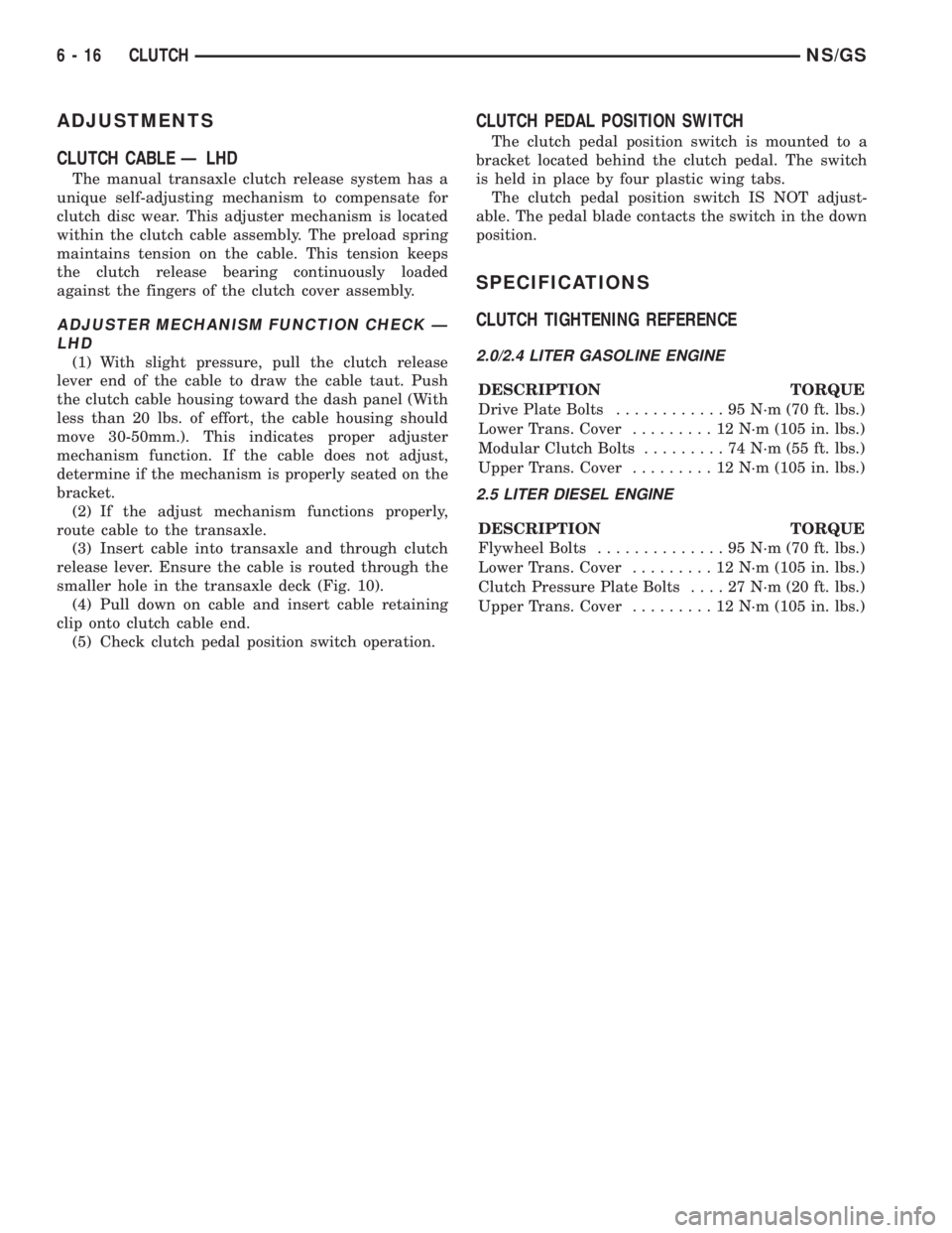
CLUTCH TIGHTENING REFERENCE
2.0/2.4 LITER GASOLINE ENGINE
DESCRIPTION TORQUE
Drive Plate Bolts............95N´m(70ft.lbs.)
Lower Trans. Cover.........12N´m(105 in. lbs.)
Modular Clutch Bolts.........74N´m(55ft.lbs.)
Upper Trans. Cover.........12N´m(105 in. lbs.)
2.5 LITER DIESEL ENGINE
DESCRIPTION TORQUE
Flywheel Bolts..............95N´m(70ft.lbs.)
Lower Trans. Cover.........12N´m(105 in. lbs.)
Clutch Pressure Plate Bolts....27N´m(20ft.lbs.)
Upper Trans. Cover.........12N´m(105 in. lbs.)
6 - 16 CLUTCHNS/GS