OBD port CHRYSLER VOYAGER 1996 Service Manual
[x] Cancel search | Manufacturer: CHRYSLER, Model Year: 1996, Model line: VOYAGER, Model: CHRYSLER VOYAGER 1996Pages: 1938, PDF Size: 55.84 MB
Page 287 of 1938

CHARGING SYSTEM
CONTENTS
page page
GENERAL INFORMATION
OVERVIEW............................. 1
DESCRIPTION AND OPERATION
BATTERY TEMPERATURE SENSOR.......... 2
CHARGING SYSTEM OPERATION........... 1
ELECTRONIC VOLTAGE REGULATOR......... 2
GENERATOR............................ 2
DIAGNOSIS AND TESTING
CHARGING SYSTEM RESISTANCE TESTS..... 4
CHARGING SYSTEM...................... 2CURRENT OUTPUT TEST.................. 4
ON-BOARD DIAGNOSTIC SYSTEM TEST...... 7
REMOVAL AND INSTALLATION
GENERATORÐ2.4L ENGINE................ 9
GENERATORÐ3.0L ENGINE................ 9
GENERATORÐ3.3/3.8 L ENGINE........... 10
SPECIFICATIONS
GENERATOR........................... 11
TORQUE.............................. 11
GENERAL INFORMATION
OVERVIEW
The battery, starting, and charging systems oper-
ate with one another, and must be tested as a com-
plete system. In order for the vehicle to start and
charge properly, all of the components involved in
these systems must perform within specifications.
Group 8A covers the battery, Group 8B covers the
starting system, and Group 8C covers the charging
system. Refer to Group 8W - Wiring Diagrams for
complete circuit descriptions and diagrams. We have
separated these systems to make it easier to locate
the information you are seeking within this Service
Manual. However, when attempting to diagnose any
of these systems, it is important that you keep their
interdependency in mind.
The diagnostic procedures used in these groups
include the most basic conventional diagnostic meth-
ods to the more sophisticated On-Board Diagnostics
(OBD) built into the Powertrain Control Module
(PCM). Use of an induction ammeter, volt/ohmmeter,
battery charger, carbon pile rheostat (load tester),
and 12-volt test lamp may be required.
All OBD-sensed systems are monitored by the
PCM. Each monitored circuit is assigned a Diagnos-
tic Trouble Code (DTC). The PCM will store a DTC in
electronic memory for any failure it detects. See the
On-Board Diagnostics Test in Group 8C - Charging
System for more information.
DESCRIPTION AND OPERATION
CHARGING SYSTEM OPERATION
The charging system consists of:
²Generator
²Electronic Voltage Regulator (EVR) circuitry
within the Powertrain Control Module (PCM)
²Ignition switch (refer to Group 8D, Ignition Sys-
tem for information)
²Battery (refer to Group 8A, Battery for informa-
tion)
²Temperature is measured by a sensor in the
PCM circuitry
²Wiring harness and connections (refer to Group
8W, Wiring for information)
The charging system is turned on and off with the
ignition switch. When the ignition switch is turned to
the ON position, battery voltage is applied to the
generator rotor through one of the two field termi-
nals to produce a magnetic field. The generator is
driven by the engine through a serpentine belt and
pulley arrangement.
The amount of DC current produced by the gener-
ator is controlled by the EVR (field control) circuitry,
contained within the PCM. This circuitry is con-
nected in series with the second rotor field terminal
and ground.
All vehicles are equipped with On-Board Diagnos-
tics (OBD). All OBD-sensed systems, including the
EVR (field control) circuitry, are monitored by the
PCM. Each monitored circuit is assigned a Diagnos-
tic Trouble Code (DTC). The PCM will store a DTC in
electronic memory for any failure it detects. See On-
Board Diagnostic System Test in this group for more
information.
NSCHARGING SYSTEM 8C - 1
Page 293 of 1938

TEST
(1) Perform the previous test Preparation.
(2) Fully engage the parking brake.
(3) Start engine.
(4) Bring engine speed to 2500 rpm.
(5) With engine speed held at 2500 rpm, slowly
adjust the rheostat control (load) on the tester to
obtain the highest amperage reading. Do not allow
voltage to drop below 12 volts. Record the reading.
This load test must be performed within 15 sec-
onds to prevent damage to test equipment.On
certain brands of test equipment, this load will be
applied automatically. Refer to the operating manual
supplied with test equipment.
(6) The ammeter reading must meet the Minimum
Test Amps specifications as displayed in the Genera-tor Ratings chart. This can be found in the Specifica-
tions section at the end of this group. A label stating
a part reference number is attached to the generator
case. On some engines this label may be located on
the bottom of the case. Compare this reference num-
ber to the Generator Ratings chart.
(7) Rotate the load control to the OFF position.
(8) Continue holding engine speed at 2500. If EVR
circuitry is OK, amperage should drop below 15±20
amps. With all electrical accessories and vehicle
lighting off, this could take several minutes of engine
operation. If amperage did not drop, refer to the
appropriate Powertrain Diagnostic Procedures man-
ual for testing.
(9) Remove volt/amp tester.
If minimum amperage could not be met, refer to
the appropriate Powertrain Diagnostic Procedures
manual for testing.
ON-BOARD DIAGNOSTIC SYSTEM TEST
GENERAL INFORMATION
The Powertrain Control Module (PCM) monitors
critical input and output circuits of the charging sys-
tem, making sure they are operational. A Diagnostic
Trouble Code (DTC) is assigned to each input and
output circuit monitored by the OBD system. Some
circuits are checked continuously and some are
checked only under certain conditions.
If the OBD system senses that a monitored circuit
is bad, it will put a DTC into electronic memory. The
DTC will stay in electronic memory as long as the
circuit continues to be bad. The PCM is programmed
to clear the memory after 50 engine starts if the
problem does not occur again.
DIAGNOSTIC TROUBLE CODES
Refer to Group 25, On Board Diagnostic for more
information. A DTC description can be read using the
DRB scan tool. Refer to the appropriate Powertrain
Diagnostic Procedures manual for information.
A DTC does not identify which component in a cir-
cuit is bad. Thus, a DTC should be treated as a
symptom, not as the cause for the problem. In some
cases, because of the design of the diagnostic test
procedure, a DTC can be the reason for another DTC
to be set. Therefore, it is important that the test pro-
cedures be followed in sequence, to understand what
caused a DTC to be set.
ERASING DIAGNOSTIC TROUBLE CODES
The DRB Scan Tool must be used to erase a DTC.
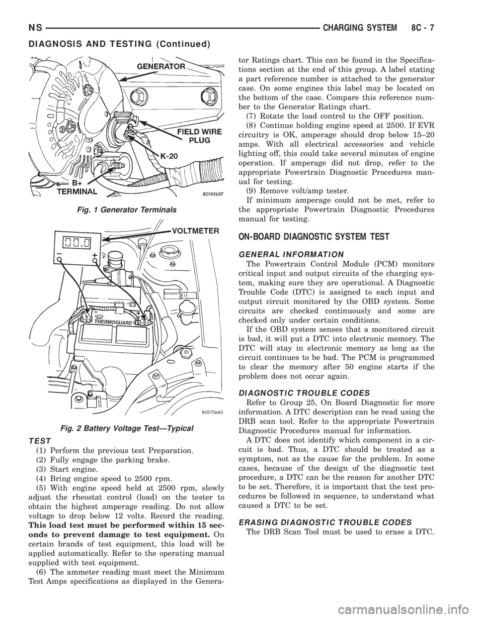
Fig. 1 Generator Terminals
Fig. 2 Battery Voltage TestÐTypical
NSCHARGING SYSTEM 8C - 7
DIAGNOSIS AND TESTING (Continued)