display CHRYSLER VOYAGER 1996 Service Manual
[x] Cancel search | Manufacturer: CHRYSLER, Model Year: 1996, Model line: VOYAGER, Model: CHRYSLER VOYAGER 1996Pages: 1938, PDF Size: 55.84 MB
Page 4 of 1938
INTRODUCTION
CONTENTS
page page
GENERAL INFORMATION
BODY CODE PLATE...................... 1
FASTENER IDENTIFICATION................ 4
INTERNATIONAL VEHICLE CONTROL AND
DISPLAY SYMBOLS..................... 4METRIC SYSTEM........................ 7
TORQUE REFERENCES................... 7
VEHICLE IDENTIFICATION NUMBER.......... 1
VEHICLE SAFETY CERTIFICATION LABEL..... 1
VIN CHECK DIGIT........................ 1
GENERAL INFORMATION
VEHICLE SAFETY CERTIFICATION LABEL
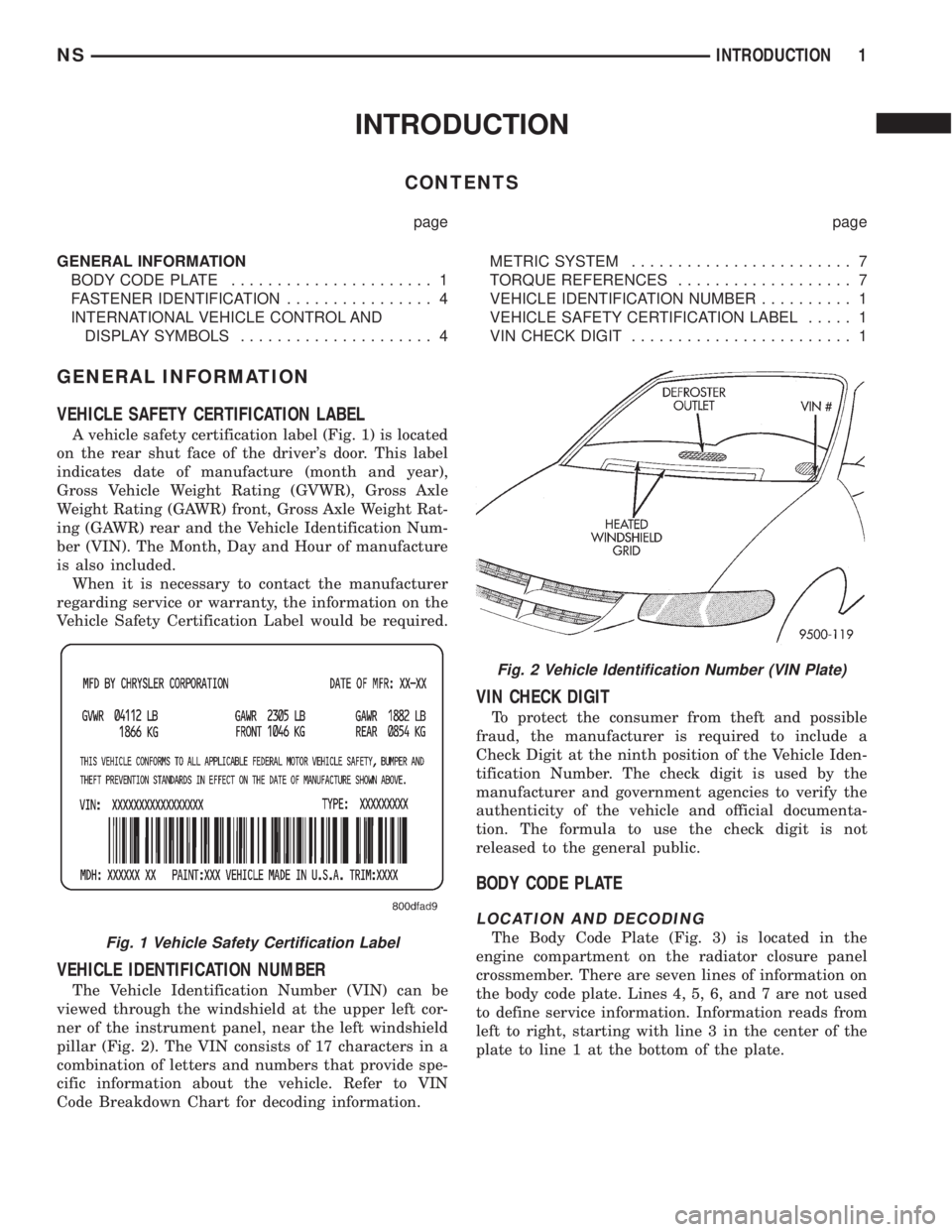
A vehicle safety certification label (Fig. 1) is located
on the rear shut face of the driver's door. This label
indicates date of manufacture (month and year),
Gross Vehicle Weight Rating (GVWR), Gross Axle
Weight Rating (GAWR) front, Gross Axle Weight Rat-
ing (GAWR) rear and the Vehicle Identification Num-
ber (VIN). The Month, Day and Hour of manufacture
is also included.
When it is necessary to contact the manufacturer
regarding service or warranty, the information on the
Vehicle Safety Certification Label would be required.
VEHICLE IDENTIFICATION NUMBER
The Vehicle Identification Number (VIN) can be
viewed through the windshield at the upper left cor-
ner of the instrument panel, near the left windshield
pillar (Fig. 2). The VIN consists of 17 characters in a
combination of letters and numbers that provide spe-
cific information about the vehicle. Refer to VIN
Code Breakdown Chart for decoding information.
VIN CHECK DIGIT
To protect the consumer from theft and possible
fraud, the manufacturer is required to include a
Check Digit at the ninth position of the Vehicle Iden-
tification Number. The check digit is used by the
manufacturer and government agencies to verify the
authenticity of the vehicle and official documenta-
tion. The formula to use the check digit is not
released to the general public.
BODY CODE PLATE
LOCATION AND DECODING
The Body Code Plate (Fig. 3) is located in the
engine compartment on the radiator closure panel
crossmember. There are seven lines of information on
the body code plate. Lines 4, 5, 6, and 7 are not used
to define service information. Information reads from
left to right, starting with line 3 in the center of the
plate to line 1 at the bottom of the plate.Fig. 1 Vehicle Safety Certification Label
Fig. 2 Vehicle Identification Number (VIN Plate)
NSINTRODUCTION 1
Page 7 of 1938
INTERNATIONAL VEHICLE CONTROL AND DISPLAY
SYMBOLS INTERNATIONAL VEHICLE CONTROL
AND DISPLAY SYMBOLS
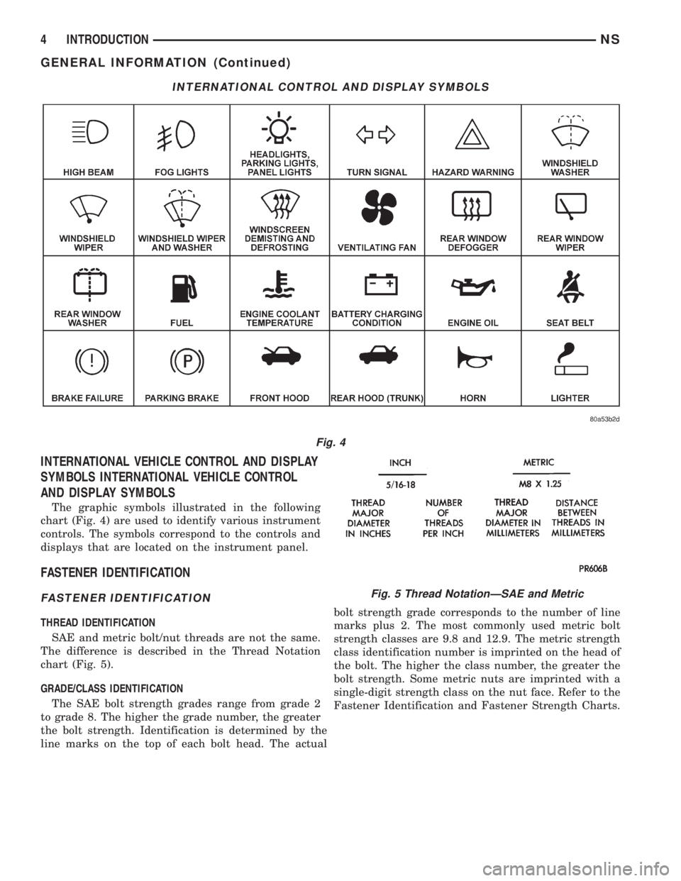
The graphic symbols illustrated in the following
chart (Fig. 4) are used to identify various instrument
controls. The symbols correspond to the controls and
displays that are located on the instrument panel.
FASTENER IDENTIFICATION
FASTENER IDENTIFICATION
THREAD IDENTIFICATION
SAE and metric bolt/nut threads are not the same.
The difference is described in the Thread Notation
chart (Fig. 5).
GRADE/CLASS IDENTIFICATION
The SAE bolt strength grades range from grade 2
to grade 8. The higher the grade number, the greater
the bolt strength. Identification is determined by the
line marks on the top of each bolt head. The actualbolt strength grade corresponds to the number of line
marks plus 2. The most commonly used metric bolt
strength classes are 9.8 and 12.9. The metric strength
class identification number is imprinted on the head of
the bolt. The higher the class number, the greater the
bolt strength. Some metric nuts are imprinted with a
single-digit strength class on the nut face. Refer to the
Fastener Identification and Fastener Strength Charts.
INTERNATIONAL CONTROL AND DISPLAY SYMBOLS
Fig. 4
Fig. 5 Thread NotationÐSAE and Metric
4 INTRODUCTIONNS
GENERAL INFORMATION (Continued)
Page 173 of 1938
The primary functions of the (CAB) are:
(1) Detect wheel locking or wheel slipping tenden-
cies by monitoring the speed of all four wheels of the
vehicle.
(2) Illuminate the TRAC lamp in the message cen-
ter on the instrument panel when a traction control
event is occurring.
(3) Control fluid modulation to the wheel brakes
while the system is in an ABS mode or the traction
control system is activated.
(4) Monitor the system for proper operation.
(5) Provide communication to the DRB Scan Tool
while in diagnostic mode.
(6) Store diagnostic information.
(7)The CAB continuously communicates with
the body controller by sending out a message to
the body controller on the CCD Bus. This mes-
sage is used for illumination of the yellow
antilock warning lamp. This is used if the ABS
controller communication is lost in the hard
wire between the body controller and the yel-
low antilock warning lamp. If the body control-
ler does not receive this message from the CAB,
the body controller will illuminate the antilock
yellow warning lamp.
The CAB continuously monitors the speed of each
wheel through the signals generated by the wheel
speed sensors to determine if any wheel is beginning
to lock. When a wheel locking tendency is detected,
the CAB commands the CAB command coils to actu-
ate. The CAB command coils then open and close the
valves in the HCU which modulate brake fluid pres-
sure in some or all of the hydraulic circuits. The CAB
continues to control pressure in individual hydraulic
circuits until a locking tendency is no longer present.
The ABS system is constantly monitored by the
CAB for proper operation. If the CAB detects a fault,
it will turn on the Amber ABS Warning Lamp anddisable the ABS braking system. The normal base
braking system will remain operational.
The CAB contains a self-diagnostic program which
will turn on the Amber ABS Warning Lamp when a
ABS system fault is detected. Faults are then stored
in a diagnostic program memory. There are multiple
fault messages which may be stored in the CAB and
displayed through the DRB Scan Tool. These fault
messages will remain in the CAB memory even after
the ignition has been turned off. The fault messages
can be read and or cleared from the CAB memory by
a technician using the DRB Scan Tool. The fault
occurrence and the fault code will also be automati-
cally cleared from the CAB memory after the identi-
cal fault has not been seen during the next 3500
miles of vehicle operation. Mileage though of the last
fault occurrence will not be automatically cleared.CONTROLLER ANTILOCK BRAKE INPUTS
²Four wheel speed sensors.
²Stop lamp switch.
²Ignition switch.
²System relay voltage.
²Ground.
²Traction Control Switch (If Equipped).
²Diagnostics Communications (CCD)
CONTROLLER ANTILOCK BRAKE OUTPUTS
²C2D Communication To Body Controller And
Instrument Cluster
²ABS warning lamp actuation.
²Traction Control Light (If Equipped).
²Diagnostic communication. (CCD)
ABS WARNING LAMP (YELLOW)
The ABS system uses a yellow colored ABS Warn-
ing Lamp. The ABS warning lamp is located on the
right side of the message center located at the top of
the instrument panel. The purpose of the warning
lamp is discussed in detail below.
The ABS warning lamp will turn on when the CAB
detects a condition which results in a shutdown of
ABS function or when the body controller does not
receive C2D messages from the CAB. When the igni-
tion key is turned to the on position, the ABS Warn-
ing Lamp is on until the CAB completes its self tests
and turns the lamp off (approximately 4 seconds
after the ignition switch is turned on). Under most
conditions, when the ABS warning lamp is on, only
the ABS function of the brake system is affected. The
standard brake system and the ability to stop the car
will not be affected when only the ABS warning lamp
is on.
The ABS warning lamp is controlled by the CAB
and the body controller through a diode located in
the wiring harness junction block. The junction block
is located under the instrument panel to the left of
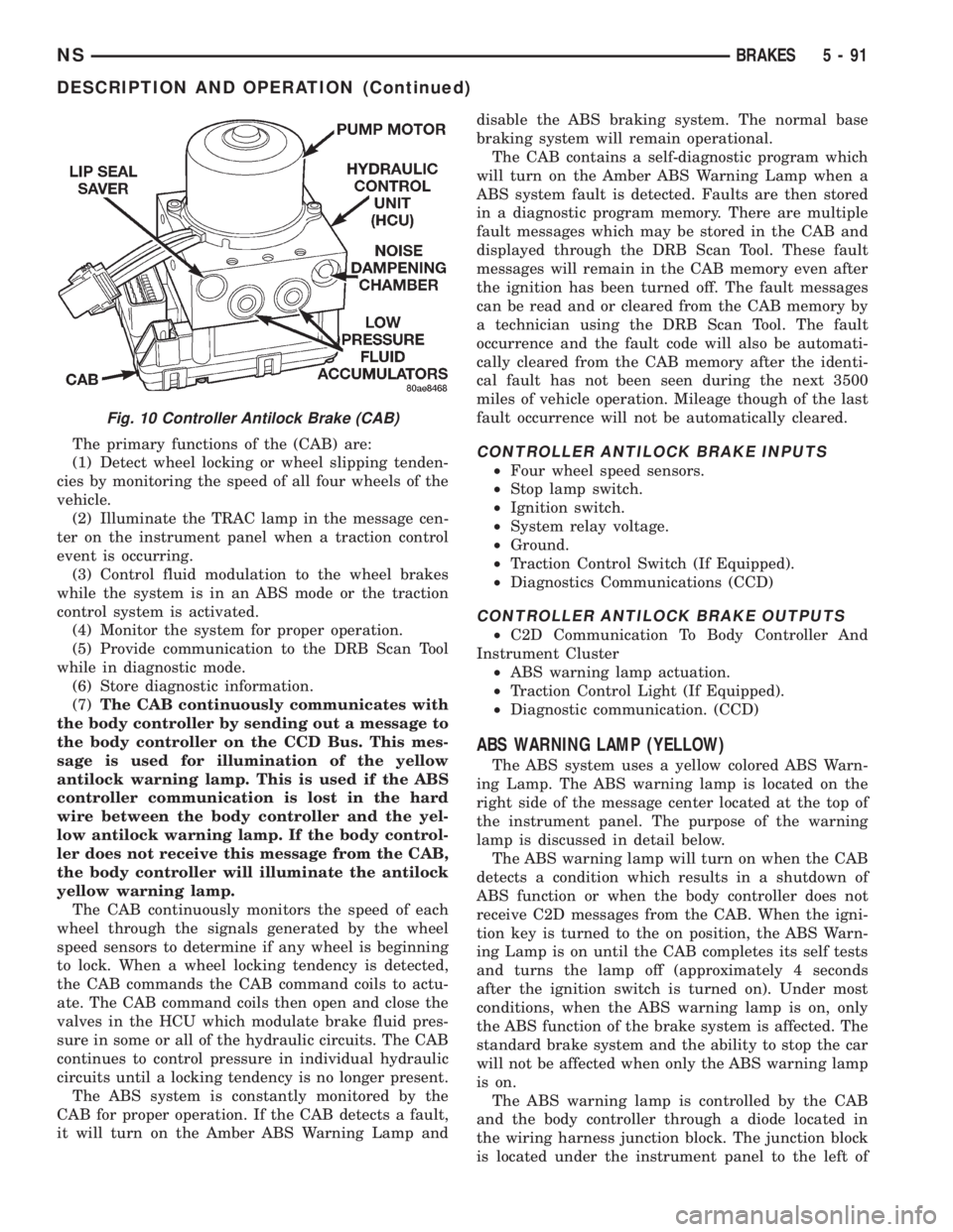
Fig. 10 Controller Antilock Brake (CAB)
NSBRAKES 5 - 91
DESCRIPTION AND OPERATION (Continued)
Page 293 of 1938
TEST
(1) Perform the previous test Preparation.
(2) Fully engage the parking brake.
(3) Start engine.
(4) Bring engine speed to 2500 rpm.
(5) With engine speed held at 2500 rpm, slowly
adjust the rheostat control (load) on the tester to
obtain the highest amperage reading. Do not allow
voltage to drop below 12 volts. Record the reading.
This load test must be performed within 15 sec-
onds to prevent damage to test equipment.On
certain brands of test equipment, this load will be
applied automatically. Refer to the operating manual
supplied with test equipment.
(6) The ammeter reading must meet the Minimum
Test Amps specifications as displayed in the Genera-tor Ratings chart. This can be found in the Specifica-
tions section at the end of this group. A label stating
a part reference number is attached to the generator
case. On some engines this label may be located on
the bottom of the case. Compare this reference num-
ber to the Generator Ratings chart.
(7) Rotate the load control to the OFF position.
(8) Continue holding engine speed at 2500. If EVR
circuitry is OK, amperage should drop below 15±20
amps. With all electrical accessories and vehicle
lighting off, this could take several minutes of engine
operation. If amperage did not drop, refer to the
appropriate Powertrain Diagnostic Procedures man-
ual for testing.
(9) Remove volt/amp tester.
If minimum amperage could not be met, refer to
the appropriate Powertrain Diagnostic Procedures
manual for testing.
ON-BOARD DIAGNOSTIC SYSTEM TEST
GENERAL INFORMATION
The Powertrain Control Module (PCM) monitors
critical input and output circuits of the charging sys-
tem, making sure they are operational. A Diagnostic
Trouble Code (DTC) is assigned to each input and
output circuit monitored by the OBD system. Some
circuits are checked continuously and some are
checked only under certain conditions.
If the OBD system senses that a monitored circuit
is bad, it will put a DTC into electronic memory. The
DTC will stay in electronic memory as long as the
circuit continues to be bad. The PCM is programmed
to clear the memory after 50 engine starts if the
problem does not occur again.
DIAGNOSTIC TROUBLE CODES
Refer to Group 25, On Board Diagnostic for more
information. A DTC description can be read using the
DRB scan tool. Refer to the appropriate Powertrain
Diagnostic Procedures manual for information.
A DTC does not identify which component in a cir-
cuit is bad. Thus, a DTC should be treated as a
symptom, not as the cause for the problem. In some
cases, because of the design of the diagnostic test
procedure, a DTC can be the reason for another DTC
to be set. Therefore, it is important that the test pro-
cedures be followed in sequence, to understand what
caused a DTC to be set.
ERASING DIAGNOSTIC TROUBLE CODES
The DRB Scan Tool must be used to erase a DTC.
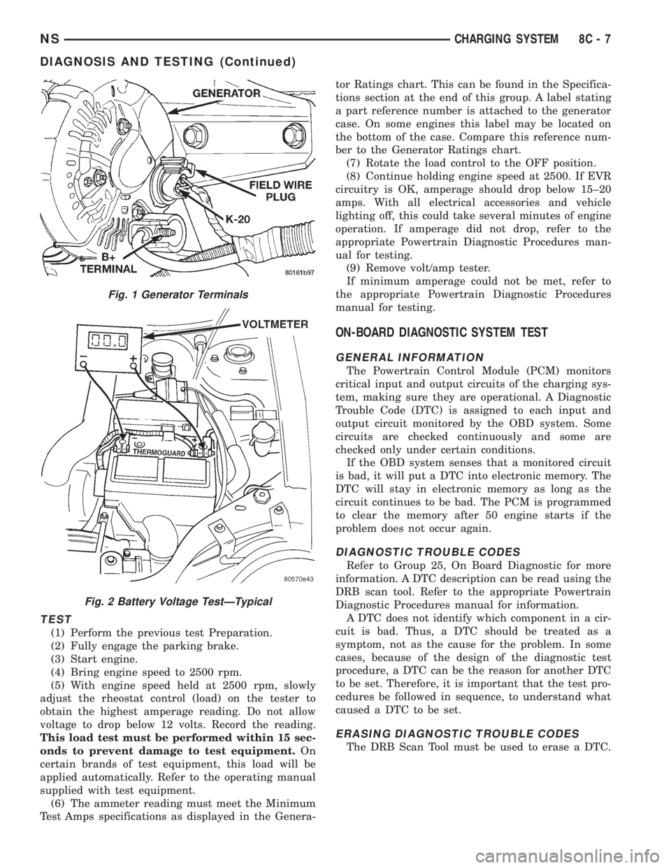
Fig. 1 Generator Terminals
Fig. 2 Battery Voltage TestÐTypical
NSCHARGING SYSTEM 8C - 7
DIAGNOSIS AND TESTING (Continued)
Page 300 of 1938
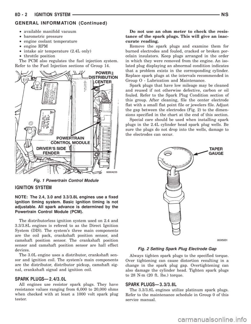
²available manifold vacuum
²barometric pressure
²engine coolant temperature
²engine RPM
²intake air temperature (2.4L only)
²throttle position
The PCM also regulates the fuel injection system.
Refer to the Fuel Injection sections of Group 14.
IGNITION SYSTEM
NOTE: The 2.4, 3.0 and 3.3/3.8L engines use a fixed
ignition timing system. Basic ignition timing is not
adjustable. All spark advance is determined by the
Powertrain Control Module (PCM).
The distributorless ignition system used on 2.4 and
3.3/3.8L engines is refered to as the Direct Ignition
System (DIS). The system's three main components
are the coil pack, crankshaft position sensor, and
camshaft position sensor. The crankshaft position
sensor and camshaft position sensor are hall effect
devices.
The 3.0L engine uses a distributor, crankshaft sen-
sor and ignition coil. The system's main components
are the distributor, distributor pickup, camshaft sig-
nal, crankshaft signal and ignition coil.
SPARK PLUGSÐ2.4/3.0L
All engines use resistor spark plugs. They have
resistance values ranging from 6,000 to 20,000 ohms
when checked with at least a 1000 volt spark plug
tester.Do not use an ohm meter to check the resis-
tance of the spark plugs. This will give an inac-
curate reading.
Remove the spark plugs and examine them for
burned electrodes and fouled, cracked or broken por-
celain insulators. Keep plugs arranged in the order
in which they were removed from the engine. An iso-
lated plug displaying an abnormal condition indicates
that a problem exists in the corresponding cylinder.
Replace spark plugs at the intervals recommended in
Group O - Lubrication and Maintenance.
Spark plugs that have low mileage may be cleaned
and reused if not otherwise defective, carbon or oil
fouled. Refer to the Spark Plug Condition section of
this group. After cleaning, file the center electrode
flat with a small flat point file or jewelers file. Adjust
the gap between the electrodes (Fig. 2) to the dimen-
sions specified in the chart at the end of this section.
Special care should be used when installing spark
plugs in the 2.4L cylinder head spark plug wells. Be
sure the plugs do not drop into the wells, damage to
the electrodes can occur.
Always tighten spark plugs to the specified torque.
Over tightening can cause distortion resulting in a
change in the spark plug gap. Overtightening can
also damage the cylinder head. Tighten spark plugs
to 28 N´m (20 ft. lbs.) torque.SPARK PLUGSÐ3.3/3.8L
The 3.3/3.8L engines utilize platinum spark plugs.
Refer to the maintenance schedule in Group 0 of this
service manual.
Fig. 1 Powertrain Control Module
Fig. 2 Setting Spark Plug Electrode Gap
8D - 2 IGNITION SYSTEMNS
GENERAL INFORMATION (Continued)
Page 301 of 1938
All engines use resistor spark plugs. They have
resistance values ranging from 6,000 to 20,000 ohms
when checked with at least a 1000 volt spark plug
tester.
Do not use an ohm meter to check the resis-
tance of the spark plugs. This will give an inac-
curate reading.
Remove the spark plugs and examine them for
burned electrodes and fouled, cracked or broken por-
celain insulators. Keep plugs arranged in the order
in which they were removed from the engine. An iso-
lated plug displaying an abnormal condition indicates
that a problem exists in the corresponding cylinder.
Replace spark plugs at the intervals recommended in
Group O - Lubrication and Maintenance.
Spark plugs that have low mileage may be cleaned
and reused if not otherwise defective, carbon or oil
fouled. Refer to the Spark Plug Condition section of
this group.
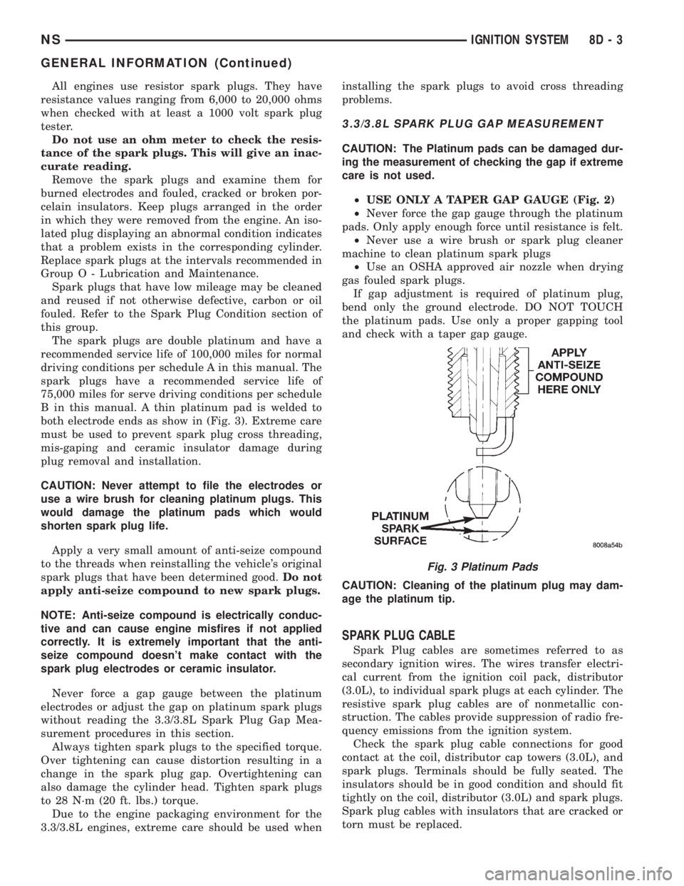
The spark plugs are double platinum and have a
recommended service life of 100,000 miles for normal
driving conditions per schedule A in this manual. The
spark plugs have a recommended service life of
75,000 miles for serve driving conditions per schedule
B in this manual. A thin platinum pad is welded to
both electrode ends as show in (Fig. 3). Extreme care
must be used to prevent spark plug cross threading,
mis-gaping and ceramic insulator damage during
plug removal and installation.
CAUTION: Never attempt to file the electrodes or
use a wire brush for cleaning platinum plugs. This
would damage the platinum pads which would
shorten spark plug life.
Apply a very small amount of anti-seize compound
to the threads when reinstalling the vehicle's original
spark plugs that have been determined good.Do not
apply anti-seize compound to new spark plugs.
NOTE: Anti-seize compound is electrically conduc-
tive and can cause engine misfires if not applied
correctly. It is extremely important that the anti-
seize compound doesn't make contact with the
spark plug electrodes or ceramic insulator.
Never force a gap gauge between the platinum
electrodes or adjust the gap on platinum spark plugs
without reading the 3.3/3.8L Spark Plug Gap Mea-
surement procedures in this section.
Always tighten spark plugs to the specified torque.
Over tightening can cause distortion resulting in a
change in the spark plug gap. Overtightening can
also damage the cylinder head. Tighten spark plugs
to 28 N´m (20 ft. lbs.) torque.
Due to the engine packaging environment for the
3.3/3.8L engines, extreme care should be used wheninstalling the spark plugs to avoid cross threading
problems.
3.3/3.8L SPARK PLUG GAP MEASUREMENT
CAUTION: The Platinum pads can be damaged dur-
ing the measurement of checking the gap if extreme
care is not used.
²USE ONLY A TAPER GAP GAUGE (Fig. 2)
²Never force the gap gauge through the platinum
pads. Only apply enough force until resistance is felt.
²Never use a wire brush or spark plug cleaner
machine to clean platinum spark plugs
²Use an OSHA approved air nozzle when drying
gas fouled spark plugs.
If gap adjustment is required of platinum plug,
bend only the ground electrode. DO NOT TOUCH
the platinum pads. Use only a proper gapping tool
and check with a taper gap gauge.
CAUTION: Cleaning of the platinum plug may dam-
age the platinum tip.
SPARK PLUG CABLE
Spark Plug cables are sometimes referred to as
secondary ignition wires. The wires transfer electri-
cal current from the ignition coil pack, distributor
(3.0L), to individual spark plugs at each cylinder. The
resistive spark plug cables are of nonmetallic con-
struction. The cables provide suppression of radio fre-
quency emissions from the ignition system.
Check the spark plug cable connections for good
contact at the coil, distributor cap towers (3.0L), and
spark plugs. Terminals should be fully seated. The
insulators should be in good condition and should fit
tightly on the coil, distributor (3.0L) and spark plugs.
Spark plug cables with insulators that are cracked or
torn must be replaced.
Fig. 3 Platinum Pads
NSIGNITION SYSTEM 8D - 3
GENERAL INFORMATION (Continued)
Page 304 of 1938

cylinder 4 crankshaft timing marks follow. One cam-
shaft pulse after the 3 pulses indicates cylinder 5.
The 2 camshaft pulses after cylinder 5 signals cylin-
der 6 (Fig. 10). The PCM can synchronize on cylin-
ders1or4.
When metal aligns with the sensor, voltage goes
low (less than 0.3 volts). When a notch aligns with
the sensor, voltage switches high (5.0 volts). As a
group of notches pass under the sensor, the voltage
switches from low (metal) to high (notch) then back
to low. The number of notches determine the amount
of pulses. If available, an oscilloscope can display the
square wave patterns of each timing event.
Top Dead Center (TDC) does not occur when
notches on the camshaft sprocket pass below the cyl-
inder. TDC occurs after the camshaft pulse (or
pulses) and after the 4 crankshaft pulses associated
with the particular cylinder. The arrows and cylinder
call outs on Figure 4 represent which cylinder the
flat spot and notches identify, they do not indicate
TDC position.
The camshaft position sensor is mounted in the
front of the timing case cover (Fig. 11).
MANIFOLD ABSOLUTE PRESSURE (MAP) SENSOR
The MAP sensor reacts to absolute pressure in the
intake manifold and provides an input voltage to the
Powertrain Control Module (PCM). As engine load
changes, manifold pressure varies. The changes in
engine load cause the MAP sensors resistance to
change. The change in MAP sensor resistance results
in a different input voltage to the PCM.
The input voltage level supplies the PCM with
information relating to ambient barometric pressure
during engine start-up (cranking) and engine load
while its operating. Based on MAP sensor voltage
and inputs from other sensors, the PCM adjusts
spark advance and the air-fuel mixture.
ENGINE COOLANT TEMPERATURE (ECT) SENSOR
The ECT sensor is located next to the thermostat
housing (Fig. 12). The sensor provides an input volt-
age to the Powertrain Control Module (PCM). Thesensor is a variable resistance (thermistor) with a
range of -40ÉF to 265ÉF. As coolant temperature var-
ies, the sensors resistance changes, resulting in a dif-
ferent input voltage to the PCM.
The PCM contains different spark advance sched-
ules for cold and warm engine operation. The sched-
ules reduce engine emission and improve driveability.
When the engine is cold, the PCM will demand
slightly richer air-fuel mixtures and higher idle
speeds until normal operating temperatures are
reached.
The ECT sensor input is also used for cooling fan
control.
Fig. 9 Camshaft Position Sensor
Fig. 10 Camshaft Sprocket
Fig. 11 Camshaft Position Sensor Location
8D - 6 IGNITION SYSTEMNS
GENERAL INFORMATION (Continued)
Page 314 of 1938
2.4L ENGINE
INDEX
page page
DESCRIPTION AND OPERATION
CAMSHAFT POSITION SENSOR............ 17
CRANKSHAFT POSITION SENSOR.......... 16
FIRING ORDERÐ2.4L.................... 16
INTAKE AIR TEMPERATURE SENSORÐ2.4L . . . 17
REMOVAL AND INSTALLATION
CAMSHAFT POSITION SENSOR............ 19
CRANKSHAFT POSITION SENSOR.......... 19
ENGINE COOLANT TEMPERATURE SENSORÐ
2.4L................................. 20
IGNITION COILÐ2.4L..................... 18
INTAKE AIR TEMPERATURE SENSORÐ2.4L . . . 21KNOCK SENSORÐ2.4L................... 21
MANIFOLD ABSOLUTE PRESSURE (MAP)
SENSORÐ2.4/3.3/3.8L.................. 20
SPARK PLUG CABLE SERVICEÐ2.4L........ 18
SPARK PLUG SERVICE................... 18
THROTTLE POSITION SENSOR............ 20
SPECIFICATIONS
IGNITION COIL......................... 22
SPARK PLUG CABLE RESISTANCEÐ2.4L..... 22
SPARK PLUG........................... 22
TORQUE.............................. 22
DESCRIPTION AND OPERATION
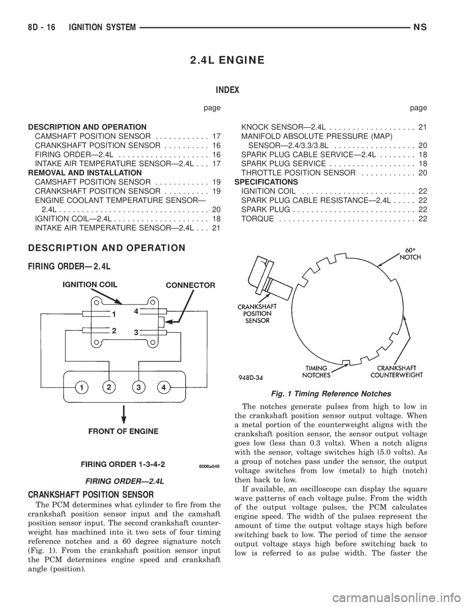
FIRING ORDERÐ2.4L
CRANKSHAFT POSITION SENSOR
The PCM determines what cylinder to fire from the
crankshaft position sensor input and the camshaft
position sensor input. The second crankshaft counter-
weight has machined into it two sets of four timing
reference notches and a 60 degree signature notch
(Fig. 1). From the crankshaft position sensor input
the PCM determines engine speed and crankshaft
angle (position).The notches generate pulses from high to low in
the crankshaft position sensor output voltage. When
a metal portion of the counterweight aligns with the
crankshaft position sensor, the sensor output voltage
goes low (less than 0.3 volts). When a notch aligns
with the sensor, voltage switches high (5.0 volts). As
a group of notches pass under the sensor, the output
voltage switches from low (metal) to high (notch)
then back to low.
If available, an oscilloscope can display the square
wave patterns of each voltage pulse. From the width
of the output voltage pulses, the PCM calculates
engine speed. The width of the pulses represent the
amount of time the output voltage stays high before
switching back to low. The period of time the sensor
output voltage stays high before switching back to
low is referred to as pulse width. The faster the
FIRING ORDERÐ2.4L
Fig. 1 Timing Reference Notches
8D - 16 IGNITION SYSTEMNS
Page 337 of 1938
INSTRUMENT PANEL AND SYSTEMS
CONTENTS
page page
GENERAL INFORMATION
INTRODUCTION......................... 1
DESCRIPTION AND OPERATION
INSTRUMENT CLUSTER................... 1
DIAGNOSIS AND TESTING
DIAGNOSTIC PROCEDURES................ 2
HEADLAMP SWITCH..................... 2
SELF DIAGNOSTIC TEST.................. 2
TRACTION CONTROL SWITCH............. 17
REMOVAL AND INSTALLATION
BODY CONTROL MODULE (BCM).......... 18
CONVENIENCE BIN - CUP HOLDER......... 17
CONVENIENCE BIN LAMP................ 17
CONVENIENCE BIN TRACK............... 18
GLOVE BOX LAMP AND SWITCH.......... 19
GLOVE BOX LOCK STRIKER.............. 20
GLOVE BOX........................... 19
HEADLAMP SWITCH LAMP(S)............ 21
HEADLAMP SWITCH.................... 20
HVAC CONTROL LAMP.................. 21
INSTRUMENT CLUSTER BACK PANEL...... 21
INSTRUMENT CLUSTER BEZEL............ 21
INSTRUMENT CLUSTER ELECTRONIC
ODOMETER AND TRANSMISSION RANGE
INDICATOR.......................... 19
INSTRUMENT CLUSTER LAMPS........... 22
INSTRUMENT CLUSTER LENS - MECHANICAL
TRANSMISSION RANGE INDICATOR
(PRND21)........................... 19
INSTRUMENT CLUSTER LENS............. 22INSTRUMENT CLUSTER PRINTED CIRCUIT
BOARD.............................. 23
INSTRUMENT CLUSTER SUBDIAL.......... 23
INSTRUMENT CLUSTER SUBDIALÐ
MECHANICAL TRANSMISSION RANGE
INDICATOR.......................... 23
INSTRUMENT CLUSTER WITH ELECTRONIC
TRANSMISSION RANGE INDICATOR...... 23
INSTRUMENT CLUSTER WITH MECHANICAL
TRANSMISSION RANGE INDICATOR...... 24
INSTRUMENT PANEL LEFT END COVER..... 27
INSTRUMENT PANEL LOUVERS........... 27
INSTRUMENT PANEL RIGHT END COVER.... 29
INSTRUMENT PANEL TOP COVER.......... 29
INSTRUMENT PANEL.................... 25
JUNCTION BLOCK...................... 30
KNEE BLOCKER REINFORCEMENT......... 30
LOWER CONSOLE...................... 30
LOWER INSTRUMENT PANEL............. 31
LOWER STEERING COLUMN COVER........ 31
MECHANICAL TRANSMISSION RANGE
INDICATOR.......................... 32
MESSAGE CENTER LAMP................ 32
MESSAGE CENTER...................... 32
OUTLET (12 VOLT) BASE................. 32
OVER STEERING COLUMN BEZEL.......... 32
POWER MIRROR SWITCH LAMP.......... 34
POWER MIRROR SWITCH................ 34
RADIO BEZEL AND HVAC CONTROL........ 34
REAR HEATER-A/C SWITCH LAMP......... 35
REAR HEATER-A/C SWITCH............... 35
TRACTION CONTROL SWITCH............. 35
GENERAL INFORMATION
INTRODUCTION
The instrumentation gauges on NS vehicles are
contained in a subdial assemblies within the instru-
ment cluster. The individual gauges are not serviced
separately. If one of the cluster gauges becomes
faulty the entire subdial would require replacement
and all gauges will have to be calibrated. Refer to the
proper Body Diagnostic Procedure Manual for cali-
bration procedures.
DESCRIPTION AND OPERATION
INSTRUMENT CLUSTER
The mechanical instrument cluster with a tachom-
eter is equipped with a electronic vacuum fluorescent
transmission range indicator (PRND3L), odometer,
and trip odometer display.
The mechanical instrument cluster without a
tachometer is equipped with a cable operated trans-
mission range indicator (PRND21).
NSINSTRUMENT PANEL AND SYSTEMS 8E - 1
Page 338 of 1938
The instrument cluster is equipped with the follow-
ing warning lamps.
²Lift Gate Ajar
²Low Fuel Level
²Low Windshield Washer Fluid Level
²Cruise
²Battery Voltage
²Fasten Seat Belt
²Door Ajar
DIAGNOSIS AND TESTING
DIAGNOSTIC PROCEDURES
NS vehicle instrument clusters are equipped with a
self diagnostic test feature to help identify electronic
problems. Prior to any test, perform Self Diagnostic
Test. The self diagnostic system monitors the CCD
bus messages. If an electronic problem occurs, a
Diagnostic Trouble Code (DTC) will be displayed in
the odometer window of the cluster.
The following CCD bus messages are continuously
monitored by the diagnostic system:
²Body Control Module
²Powertrain Control Module
²Transmission Control Module, if equipped
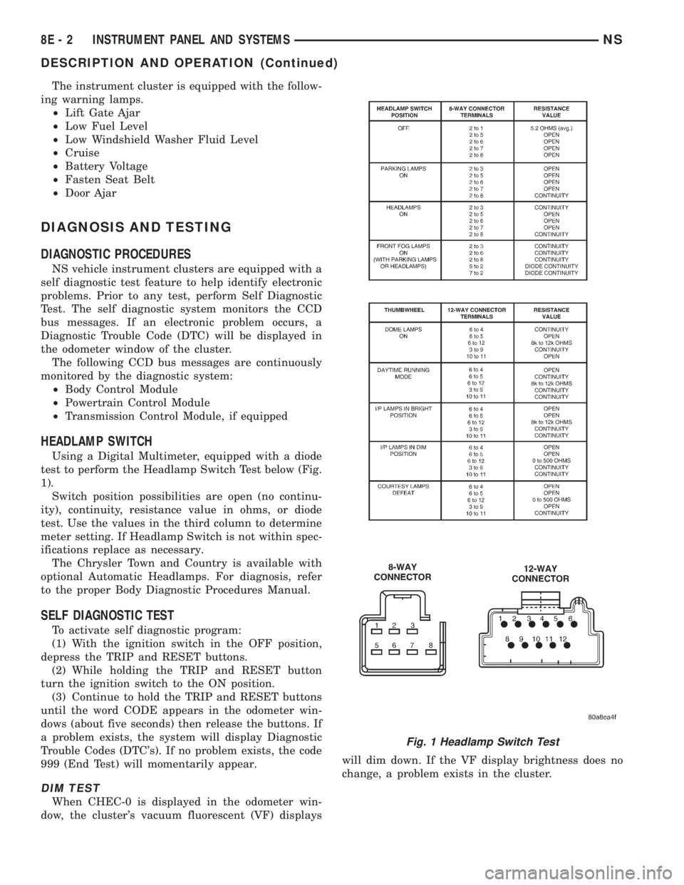
HEADLAMP SWITCH
Using a Digital Multimeter, equipped with a diode
test to perform the Headlamp Switch Test below (Fig.
1).
Switch position possibilities are open (no continu-
ity), continuity, resistance value in ohms, or diode
test. Use the values in the third column to determine
meter setting. If Headlamp Switch is not within spec-
ifications replace as necessary.
The Chrysler Town and Country is available with
optional Automatic Headlamps. For diagnosis, refer
to the proper Body Diagnostic Procedures Manual.
SELF DIAGNOSTIC TEST
To activate self diagnostic program:
(1) With the ignition switch in the OFF position,
depress the TRIP and RESET buttons.
(2) While holding the TRIP and RESET button
turn the ignition switch to the ON position.
(3) Continue to hold the TRIP and RESET buttons
until the word CODE appears in the odometer win-
dows (about five seconds) then release the buttons. If
a problem exists, the system will display Diagnostic
Trouble Codes (DTC's). If no problem exists, the code
999 (End Test) will momentarily appear.
DIM TEST
When CHEC-0 is displayed in the odometer win-
dow, the cluster's vacuum fluorescent (VF) displayswill dim down. If the VF display brightness does no
change, a problem exists in the cluster.
Fig. 1 Headlamp Switch Test
8E - 2 INSTRUMENT PANEL AND SYSTEMSNS
DESCRIPTION AND OPERATION (Continued)