ESP CHRYSLER VOYAGER 1996 Service Manual
[x] Cancel search | Manufacturer: CHRYSLER, Model Year: 1996, Model line: VOYAGER, Model: CHRYSLER VOYAGER 1996Pages: 1938, PDF Size: 55.84 MB
Page 7 of 1938
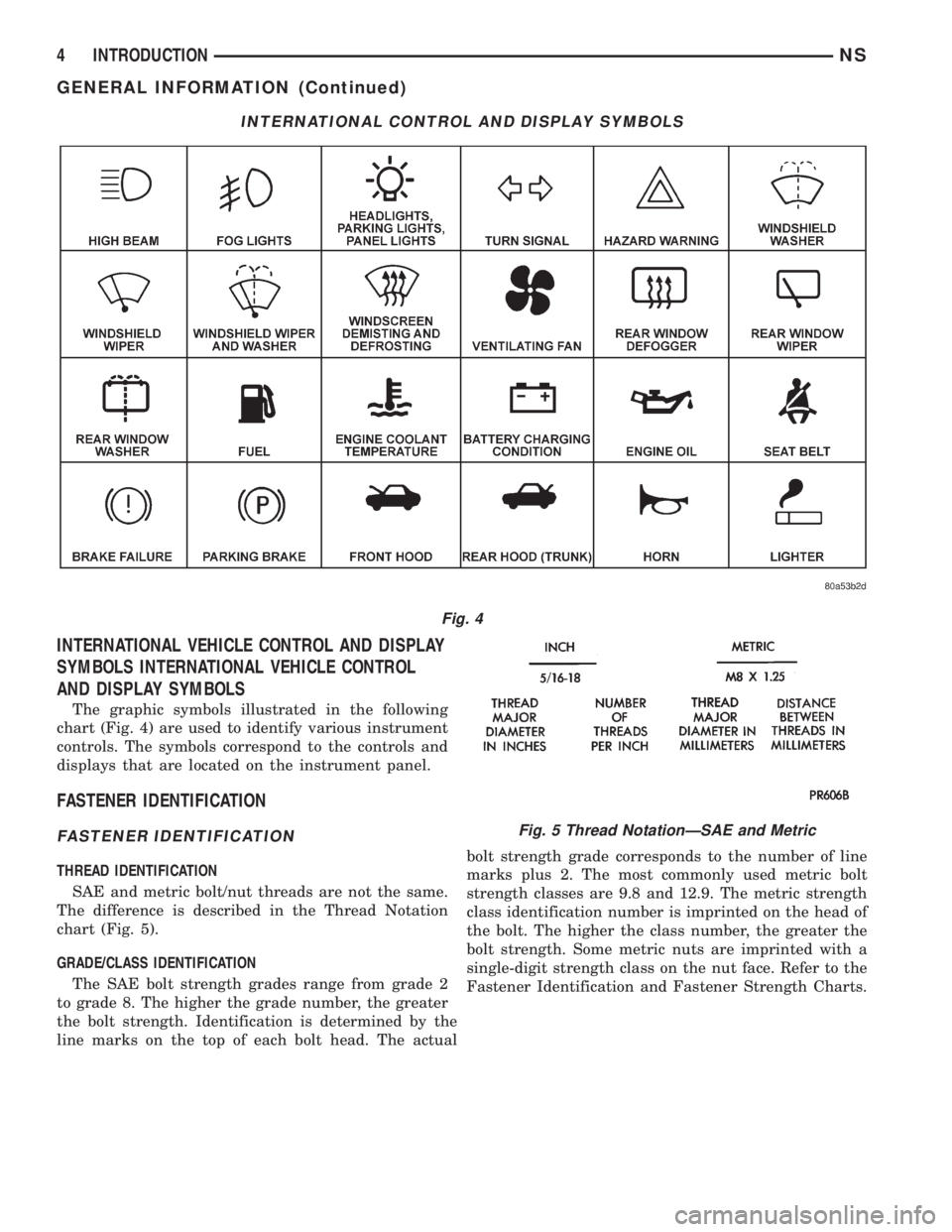
INTERNATIONAL VEHICLE CONTROL AND DISPLAY
SYMBOLS INTERNATIONAL VEHICLE CONTROL
AND DISPLAY SYMBOLS
The graphic symbols illustrated in the following
chart (Fig. 4) are used to identify various instrument
controls. The symbols correspond to the controls and
displays that are located on the instrument panel.
FASTENER IDENTIFICATION
FASTENER IDENTIFICATION
THREAD IDENTIFICATION
SAE and metric bolt/nut threads are not the same.
The difference is described in the Thread Notation
chart (Fig. 5).
GRADE/CLASS IDENTIFICATION
The SAE bolt strength grades range from grade 2
to grade 8. The higher the grade number, the greater
the bolt strength. Identification is determined by the
line marks on the top of each bolt head. The actualbolt strength grade corresponds to the number of line
marks plus 2. The most commonly used metric bolt
strength classes are 9.8 and 12.9. The metric strength
class identification number is imprinted on the head of
the bolt. The higher the class number, the greater the
bolt strength. Some metric nuts are imprinted with a
single-digit strength class on the nut face. Refer to the
Fastener Identification and Fastener Strength Charts.
INTERNATIONAL CONTROL AND DISPLAY SYMBOLS
Fig. 4
Fig. 5 Thread NotationÐSAE and Metric
4 INTRODUCTIONNS
GENERAL INFORMATION (Continued)
Page 96 of 1938
ADJUSTER REAR DRUM BRAKE (AUTOMATIC)
The rear drum brakes on this vehicle automatically
adjust, when required, during the normal operation
of the vehicle every time the brakes are applied. Use
the following procedure to test the operation of the
automatic adjuster.
Place the vehicle on a hoist with a helper in the
driver's seat to apply the brakes. Remove the access
plug from the adjustment hole in each brake support
plate to provide visual access of the brake adjuster
star wheel.
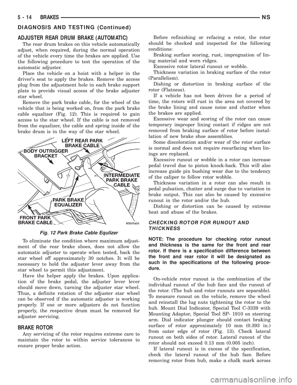
Remove the park brake cable, for the wheel of the
vehicle that is being worked on, from the park brake
cable equalizer (Fig. 12). This is required to gain
access to the star wheel. If the cable is not removed
from the equalizer, the cable and spring inside of the
brake drum is in the way of the star wheel.
To eliminate the condition where maximum adjust-
ment of the rear brake shoes, does not allow the
automatic adjuster to operate when tested, back the
star wheel off approximately 30 notches. It will be
necessary to hold the adjuster lever away from the
star wheel to permit this adjustment.
Have the helper apply the brakes. Upon applica-
tion of the brake pedal, the adjuster lever lever
should move down, turning the adjuster star wheel.
Thus, a definite rotation of the adjuster star wheel
can be observed if the automatic adjuster is working
properly. If one or more adjusters do not function
properly, the respective drum must be removed for
adjuster servicing.
BRAKE ROTOR
Any servicing of the rotor requires extreme care to
maintain the rotor to within service tolerances to
ensure proper brake action.Before refinishing or refacing a rotor, the rotor
should be checked and inspected for the following
conditions:
Braking surface scoring, rust, impregnation of lin-
ing material and worn ridges.
Excessive rotor lateral runout or wobble.
Thickness variation in braking surface of the rotor
(Parallelism).
Dishing or distortion in braking surface of the
rotor (Flatness).
If a vehicle has not been driven for a period of
time, the rotors will rust in the area not covered by
the brake lining and cause noise and chatter when
the brakes are applied.
Excessive wear and scoring of the rotor can cause
temporary improper lining contact if ridges are not
removed from braking surface of rotor before instal-
lation of new brake shoe assemblies.
Some discoloration and/or wear of the rotor surface
is normal and does not require resurfacing when lin-
ings are replaced.
Excessive runout or wobble in a rotor can increase
pedal travel due to piston knock-back. This will also
increase guide pin bushing wear due to the tendency
of the caliper to follow rotor wobble.
Thickness variation in a rotor can also result in
pedal pulsation, chatter and surge due to variation in
brake output. This can also be caused by excessive
runout in the rotor and/or the hub.
Dishing or distortion can be caused by extreme
heat and abuse of the brakes.
CHECKING ROTOR FOR RUNOUT AND
THICKNESS
NOTE: The procedure for checking rotor runout
and thickness is the same for the front and rear
rotor. If there is a specification difference between
the front and rear rotor it will be designated as
such in the specifications of the following proce-
dure.
On-vehicle rotor runout is the combination of the
individual runout of the hub face and the runout of
the rotor. (The hub and rotor runouts are separable).
To measure runout on the vehicle, remove the wheel
and reinstall the lug nuts tightening the rotor to the
hub. Mount Dial Indicator, Special Tool C-3339 with
Mounting Adaptor, Special Tool SP- 1910 on steering
arm. Dial indicator plunger should contact braking
surface of rotor approximately 10 mm (0.393 in.)
from outer edge of rotor (Fig. 13). Check lateral
runout on both sides of rotor. Lateral runout of the
rotor should not exceed 0.13 mm (0.005 inch).
If lateral runout is in excess of the specification,
check the lateral runout of the hub face. Before
removing rotor from hub, make a chalk mark across
Fig. 12 Park Brake Cable Equlizer
5 - 14 BRAKESNS
DIAGNOSIS AND TESTING (Continued)
Page 109 of 1938
(4) Remove the locking pliers from the front park
brake cable. This will allow the adjuster in the park
brake pedal mechanism to rotate around to its stop.
This will remove the tension from the adjuster and
front park brake cable.
Use the following procedure to reset the auto
adjuster in the park brake pedal mechanism.
(5) Grasp the exposed section of the front park
brake cable and pull rearward on it. While holding
the park brake in this position, install a pair of lock-
ing pliers on the front park brake cable just rearward
of the second body outrigger bracket (Fig. 42).
(6) Install the equalizer on the front park brake
cable.
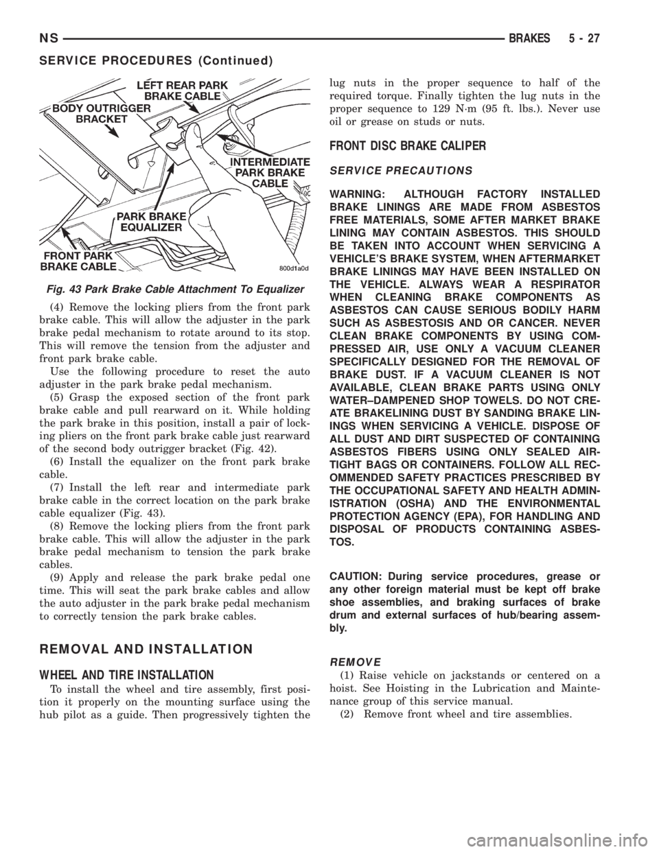
(7) Install the left rear and intermediate park
brake cable in the correct location on the park brake
cable equalizer (Fig. 43).
(8) Remove the locking pliers from the front park
brake cable. This will allow the adjuster in the park
brake pedal mechanism to tension the park brake
cables.
(9) Apply and release the park brake pedal one
time. This will seat the park brake cables and allow
the auto adjuster in the park brake pedal mechanism
to correctly tension the park brake cables.
REMOVAL AND INSTALLATION
WHEEL AND TIRE INSTALLATION
To install the wheel and tire assembly, first posi-
tion it properly on the mounting surface using the
hub pilot as a guide. Then progressively tighten thelug nuts in the proper sequence to half of the
required torque. Finally tighten the lug nuts in the
proper sequence to 129 N´m (95 ft. lbs.). Never use
oil or grease on studs or nuts.
FRONT DISC BRAKE CALIPER
SERVICE PRECAUTIONS
WARNING: ALTHOUGH FACTORY INSTALLED
BRAKE LININGS ARE MADE FROM ASBESTOS
FREE MATERIALS, SOME AFTER MARKET BRAKE
LINING MAY CONTAIN ASBESTOS. THIS SHOULD
BE TAKEN INTO ACCOUNT WHEN SERVICING A
VEHICLE'S BRAKE SYSTEM, WHEN AFTERMARKET
BRAKE LININGS MAY HAVE BEEN INSTALLED ON
THE VEHICLE. ALWAYS WEAR A RESPIRATOR
WHEN CLEANING BRAKE COMPONENTS AS
ASBESTOS CAN CAUSE SERIOUS BODILY HARM
SUCH AS ASBESTOSIS AND OR CANCER. NEVER
CLEAN BRAKE COMPONENTS BY USING COM-
PRESSED AIR, USE ONLY A VACUUM CLEANER
SPECIFICALLY DESIGNED FOR THE REMOVAL OF
BRAKE DUST. IF A VACUUM CLEANER IS NOT
AVAILABLE, CLEAN BRAKE PARTS USING ONLY
WATER±DAMPENED SHOP TOWELS. DO NOT CRE-
ATE BRAKELINING DUST BY SANDING BRAKE LIN-
INGS WHEN SERVICING A VEHICLE. DISPOSE OF
ALL DUST AND DIRT SUSPECTED OF CONTAINING
ASBESTOS FIBERS USING ONLY SEALED AIR-
TIGHT BAGS OR CONTAINERS. FOLLOW ALL REC-
OMMENDED SAFETY PRACTICES PRESCRIBED BY
THE OCCUPATIONAL SAFETY AND HEALTH ADMIN-
ISTRATION (OSHA) AND THE ENVIRONMENTAL
PROTECTION AGENCY (EPA), FOR HANDLING AND
DISPOSAL OF PRODUCTS CONTAINING ASBES-
TOS.
CAUTION: During service procedures, grease or
any other foreign material must be kept off brake
shoe assemblies, and braking surfaces of brake
drum and external surfaces of hub/bearing assem-
bly.
REMOVE
(1) Raise vehicle on jackstands or centered on a
hoist. See Hoisting in the Lubrication and Mainte-
nance group of this service manual.
(2) Remove front wheel and tire assemblies.
Fig. 43 Park Brake Cable Attachment To Equalizer
NSBRAKES 5 - 27
SERVICE PROCEDURES (Continued)
Page 112 of 1938
(9) Road test the vehicle and make several stops to
wear off any foreign material on the brakes and to
seat the brake shoe linings.
FRONT DISC BRAKE PADS
REMOVE
WARNING: ALTHOUGH FACTORY INSTALLED
BRAKE LININGS ARE MADE FROM ASBESTOS
FREE MATERIALS, SOME AFTERMARKET BRAKE
LININGS MAY CONTAIN ASBESTOS. THIS SHOULD
BE TAKEN INTO ACCOUNT WHEN SERVICING A
VEHICLE'S BRAKE SYSTEM, WHEN AFTERMARKET
BRAKE LININGS MAY HAVE BEEN INSTALLED ON
THE VEHICLE. ALWAYS WEAR A RESPIRATOR
WHEN CLEANING BRAKE COMPONENTS AS
ASBESTOS CAN CAUSE SERIOUS BODILY HARM
SUCH AS ASBESTOSIS AND OR CANCER. NEVER
CLEAN BRAKE COMPONENTS BY USING COM-
PRESSED AIR, USE ONLY A VACUUM CLEANER
SPECIFICALLY DESIGNED FOR THE REMOVAL OF
BRAKE DUST. IF A VACUUM CLEANER IS NOT
AVAILABLE, CLEAN BRAKE PARTS USING ONLY
WATER±DAMPENED SHOP TOWELS. DO NOT CRE-
ATE BRAKELINING DUST BY SANDING BRAKE LIN-
INGS WHEN SERVICING A VEHICLE. DISPOSE OF
ALL DUST AND DIRT SUSPECTED OF CONTAINING
ASBESTOS FIBERS USING ONLY SEALED AIR-
TIGHT BAGS OR CONTAINERS. FOLLOW ALL REC-
OMMENDED SAFETY PRACTICES PRESCRIBED BY
THE OCCUPATIONAL SAFETY AND HEALTH ADMIN-
ISTRATION (OSHA) AND THE ENVIRONMENTAL
PROTECTION AGENCY (EPA), FOR HANDLING AND
DISPOSAL OF PRODUCTS CONTAINING ASBES-
TOS.
CAUTION: During service procedures, grease or
any other foreign material must be kept off brake
shoe assemblies, and braking surfaces of brake
drum and external surfaces of hub/bearing assem-
bly.
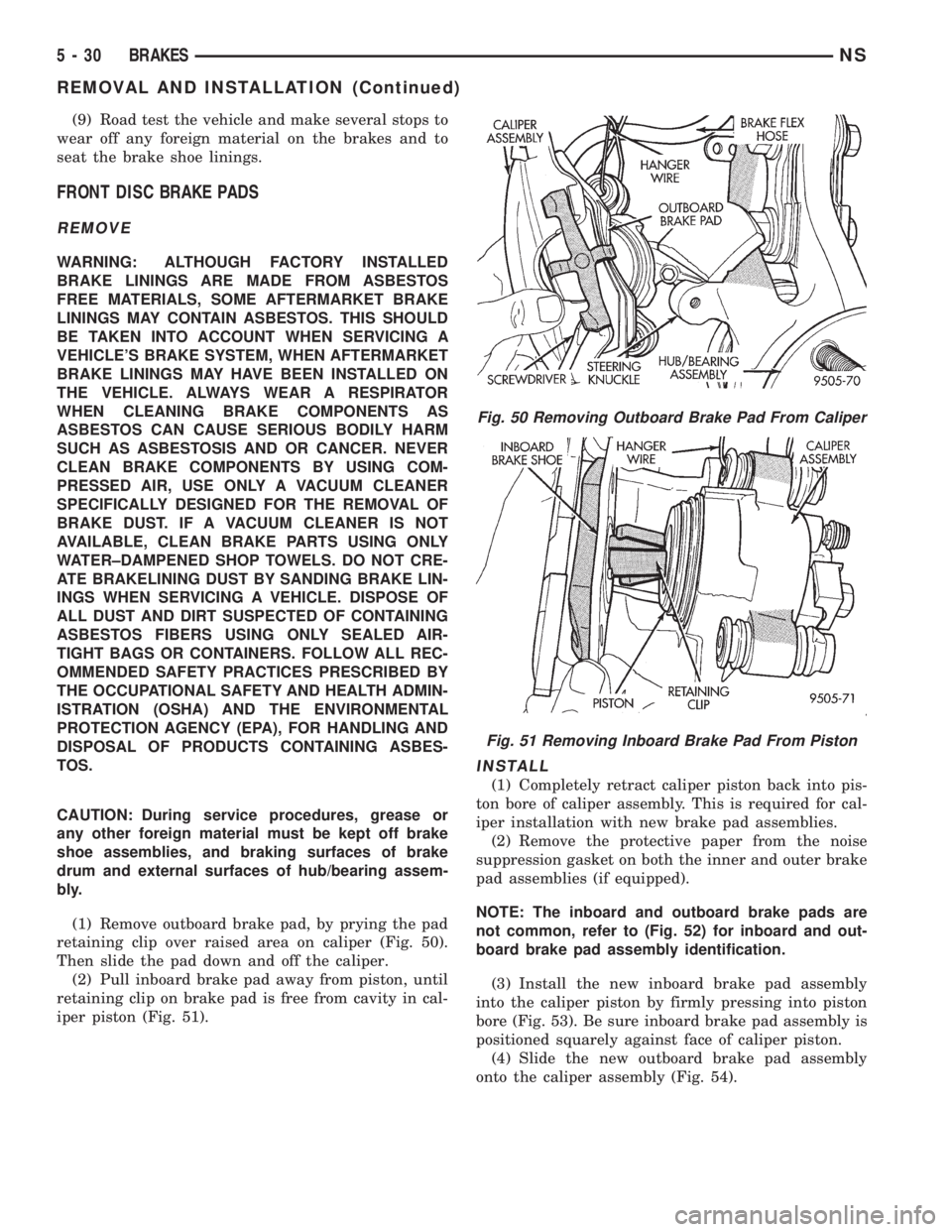
(1) Remove outboard brake pad, by prying the pad
retaining clip over raised area on caliper (Fig. 50).
Then slide the pad down and off the caliper.
(2) Pull inboard brake pad away from piston, until
retaining clip on brake pad is free from cavity in cal-
iper piston (Fig. 51).
INSTALL
(1) Completely retract caliper piston back into pis-
ton bore of caliper assembly. This is required for cal-
iper installation with new brake pad assemblies.
(2) Remove the protective paper from the noise
suppression gasket on both the inner and outer brake
pad assemblies (if equipped).
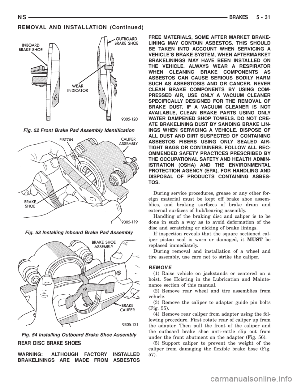
NOTE: The inboard and outboard brake pads are
not common, refer to (Fig. 52) for inboard and out-
board brake pad assembly identification.
(3) Install the new inboard brake pad assembly
into the caliper piston by firmly pressing into piston
bore (Fig. 53). Be sure inboard brake pad assembly is
positioned squarely against face of caliper piston.
(4) Slide the new outboard brake pad assembly
onto the caliper assembly (Fig. 54).
Fig. 50 Removing Outboard Brake Pad From Caliper
Fig. 51 Removing Inboard Brake Pad From Piston
5 - 30 BRAKESNS
REMOVAL AND INSTALLATION (Continued)
Page 113 of 1938
REAR DISC BRAKE SHOES
WARNING: ALTHOUGH FACTORY INSTALLED
BRAKELININGS ARE MADE FROM ASBESTOSFREE MATERIALS, SOME AFTER MARKET BRAKE-
LINING MAY CONTAIN ASBESTOS. THIS SHOULD
BE TAKEN INTO ACCOUNT WHEN SERVICING A
VEHICLE'S BRAKE SYSTEM, WHEN AFTERMARKET
BRAKELININGS MAY HAVE BEEN INSTALLED ON
THE VEHICLE. ALWAYS WEAR A RESPIRATOR
WHEN CLEANING BRAKE COMPONENTS AS
ASBESTOS CAN CAUSE SERIOUS BODILY HARM
SUCH AS ASBESTOSIS AND OR CANCER. NEVER
CLEAN BRAKE COMPONENTS BY USING COM-
PRESSED AIR, USE ONLY A VACUUM CLEANER
SPECIFICALLY DESIGNED FOR THE REMOVAL OF
BRAKE DUST. IF A VACUUM CLEANER IS NOT
AVAILABLE, CLEAN BRAKE PARTS USING ONLY
WATER DAMPENED SHOP TOWELS. DO NOT CRE-
ATE BRAKELINING DUST BY SANDING BRAKE LIN-
INGS WHEN SERVICING A VEHICLE. DISPOSE OF
ALL DUST AND DIRT SUSPECTED OF CONTAINING
ASBESTOS FIBERS USING ONLY SEALED AIR-
TIGHT BAGS OR CONTAINERS. FOLLOW ALL REC-
OMMENDED SAFETY PRACTICES PRESCRIBED BY
THE OCCUPATIONAL SAFETY AND HEALTH ADMIN-
ISTRATION (OSHA) AND THE ENVIRONMENTAL
PROTECTION AGENCY (EPA), FOR HANDLING AND
DISPOSAL OF PRODUCTS CONTAINING ASBES-
TOS.
During service procedures, grease or any other for-
eign material must be kept off brake shoe assem-
blies, and braking surfaces of brake drum and
external surfaces of hub/bearing assembly.
Handling of the braking disc and caliper is to be
done in such a way as to avoid deformation of the
disc and scratching or nicking of brake linings.
If inspection reveals that the square sectioned cal-
iper piston seal is worn or damaged, itMUSTbe
replaced immediately.
During removal and installation of a wheel and
tire assembly, use care not to strike the caliper.
REMOVE
(1) Raise vehicle on jackstands or centered on a
hoist. See Hoisting in the Lubrication and Mainte-
nance section of this manual.
(2) Remove rear wheel and tire assemblies from
vehicle.
(3) Remove the caliper to adapter guide pin bolts
(Fig. 55).
(4) Remove rear caliper from adapter using the fol-
lowing procedure. First rotate rear of caliper up from
the adapter. Then pull the front of the caliper and
the outboard brake shoe anti-rattle clip out from
under the front abutment on the adapter (Fig. 56).
(5) Support caliper to prevent the weight of the
caliper from damaging the flexible brake hose (Fig.
57).
Fig. 52 Front Brake Pad Assembly Identification
Fig. 53 Installing Inboard Brake Pad Assembly
Fig. 54 Installing Outboard Brake Shoe Assembly
NSBRAKES 5 - 31
REMOVAL AND INSTALLATION (Continued)
Page 116 of 1938
REAR DRUM BRAKE SHOES
REMOVE
WARNING: ALTHOUGH FACTORY INSTALLED
BRAKE LININGS ARE MADE FROM ASBESTOS
FREE MATERIALS, SOME AFTERMARKET BRAK-
LINING MAY CONTAIN ASBESTOS. THIS SHOULD
BE TAKEN INTO ACCOUNT WHEN SERVICING A
VEHICLE'S BRAKE SYSTEM, WHEN AFTERMARKET
BRAKE LININGS MAY HAVE BEEN INSTALLED ON
THE VEHICLE. ALWAYS WEAR A RESPIRATOR
WHEN CLEANING BRAKE COMPONENTS AS
ASBESTOS CAN CAUSE SERIOUS BODILY HARM
SUCH AS ASBESTOSIS AND OR CANCER. NEVER
CLEAN BRAKE COMPONENTS BY USING COM-
PRESSED AIR, USE ONLY A VACUUM CLEANER
SPECIFICALLY DESIGNED FOR THE REMOVAL OF
BRAKE DUST. IF A VACUUM CLEANER IS NOT
AVAILABLE, CLEAN BRAKE PARTS USING ONLY
WATER±DAMPENED SHOP TOWELS. DO NOT CRE-
ATE BRAKE LINING DUST BY SANDING BRAKE
LININGS WHEN SERVICING A VEHICLE. DISPOSE
OF ALL DUST AND DIRT SUSPECTED OF CONTAIN-
ING ASBESTOS FIBERS USING ONLY SEALED AIR-
TIGHT BAGS OR CONTAINERS. FOLLOW ALL
RECOMMENDED SAFETY PRACTICES PRE-
SCRIBED BY THE OCCUPATIONAL SAFETY AND
HEALTH ADMINISTRATION (OSHA) AND THE ENVI-
RONMENTAL PROTECTION AGENCY (EPA), FOR
HANDLING AND DISPOSAL OF PRODUCTS CON-
TAINING ASBESTOS.
(1) Raise vehicle on jackstands or centered on a
hoist. See Hoisting in the Lubrication and Mainte-
nance section of this manual.
(2) Remove the rear wheel and tire assemblies
from the vehicle.
(3) Remove rear brake drum to hub retaining nuts
(if equipped). Then remove rear brake drums from
hub and bearing assemblies.
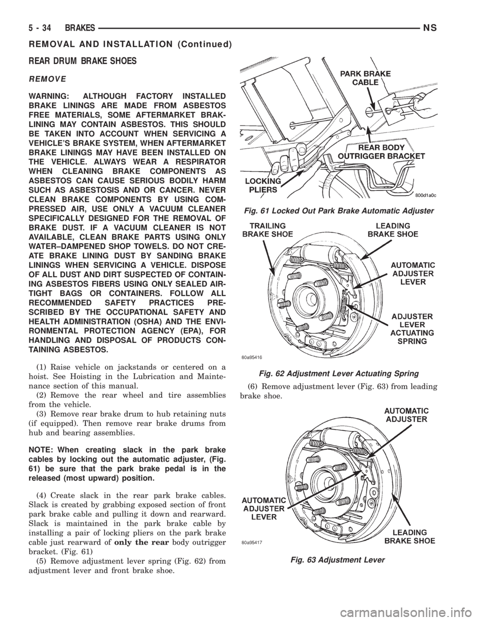
NOTE: When creating slack in the park brake
cables by locking out the automatic adjuster, (Fig.
61) be sure that the park brake pedal is in the
released (most upward) position.
(4) Create slack in the rear park brake cables.
Slack is created by grabbing exposed section of front
park brake cable and pulling it down and rearward.
Slack is maintained in the park brake cable by
installing a pair of locking pliers on the park brake
cable just rearward ofonly the rearbody outrigger
bracket. (Fig. 61)
(5) Remove adjustment lever spring (Fig. 62) from
adjustment lever and front brake shoe.(6) Remove adjustment lever (Fig. 63) from leading
brake shoe.
Fig. 61 Locked Out Park Brake Automatic Adjuster
Fig. 62 Adjustment Lever Actuating Spring
Fig. 63 Adjustment Lever
5 - 34 BRAKESNS
REMOVAL AND INSTALLATION (Continued)
Page 196 of 1938

Upon application of the brake pedal, the lever
should move down, turning the star wheel. A definite
rotation of the star wheel should be seen if the auto-
matic adjuster is working properly. If no rotation of
the star wheel is observed when the pedal is consec-
utively pressed and released, the respective drum
will have to be removed and the adjuster serviced.
MASTER CYLINDER FLUID LEVEL CHECK
The master cylinder used in this vehicle has the
same fluid level markings as the master cylinders
used in other brake systems on the side of the fluid
resevoir. Refer to the Master Cylinder Fluid Level
Check in the Diagnosis and Testing section of group
5 for more information
REMOVAL AND INSTALLATION
FRONT PARK BRAKE CABLE AND LEVER
ASSEMBLY-RHD&LHD VEHICLES
REMOVE
(1) Raise vehicle on jackstands or centered on a
hoist. See Hoisting in the Lubrication and Mainte-
nance group of this service manual.
(2) Remove the intermediate and left rear park
brake cable from the park brake cable equalizer (Fig.
2).
(3) Remove the front park cable housing retainer
from body outrigger bracket (Fig. 3). Cable is remov-
able by sliding a 14 mm box wrench over cable
retainer and compressing the three retaining fingers.
Alternate method is to use an aircraft type hose
clamp and screwdriver.(4) Remove the two (2) retaining nuts and (2)
retaining bolts from the bottom of the parking brake/
gearshift lever bracket.
(5) Lower vehicle.
(6) Carefully lift the base of the gearshift boot
from the gearshift console to access the screws (Fig.
4).
Fig. 2 Park Brake Cable Attachment To Equalizer
Fig. 3 Front Park Brake Cable Attachment To Body
Fig. 4 Console and Gearshift boot
5 - 2 BRAKESNS/GS
DIAGNOSIS AND TESTING (Continued)
Page 300 of 1938
²available manifold vacuum
²barometric pressure
²engine coolant temperature
²engine RPM
²intake air temperature (2.4L only)
²throttle position
The PCM also regulates the fuel injection system.
Refer to the Fuel Injection sections of Group 14.
IGNITION SYSTEM
NOTE: The 2.4, 3.0 and 3.3/3.8L engines use a fixed
ignition timing system. Basic ignition timing is not
adjustable. All spark advance is determined by the
Powertrain Control Module (PCM).
The distributorless ignition system used on 2.4 and
3.3/3.8L engines is refered to as the Direct Ignition
System (DIS). The system's three main components
are the coil pack, crankshaft position sensor, and
camshaft position sensor. The crankshaft position
sensor and camshaft position sensor are hall effect
devices.
The 3.0L engine uses a distributor, crankshaft sen-
sor and ignition coil. The system's main components
are the distributor, distributor pickup, camshaft sig-
nal, crankshaft signal and ignition coil.
SPARK PLUGSÐ2.4/3.0L
All engines use resistor spark plugs. They have
resistance values ranging from 6,000 to 20,000 ohms
when checked with at least a 1000 volt spark plug
tester.Do not use an ohm meter to check the resis-
tance of the spark plugs. This will give an inac-
curate reading.
Remove the spark plugs and examine them for
burned electrodes and fouled, cracked or broken por-
celain insulators. Keep plugs arranged in the order
in which they were removed from the engine. An iso-
lated plug displaying an abnormal condition indicates
that a problem exists in the corresponding cylinder.
Replace spark plugs at the intervals recommended in
Group O - Lubrication and Maintenance.
Spark plugs that have low mileage may be cleaned
and reused if not otherwise defective, carbon or oil
fouled. Refer to the Spark Plug Condition section of
this group. After cleaning, file the center electrode
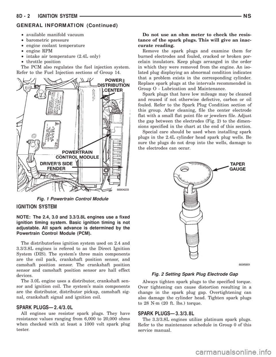
flat with a small flat point file or jewelers file. Adjust
the gap between the electrodes (Fig. 2) to the dimen-
sions specified in the chart at the end of this section.
Special care should be used when installing spark
plugs in the 2.4L cylinder head spark plug wells. Be
sure the plugs do not drop into the wells, damage to
the electrodes can occur.
Always tighten spark plugs to the specified torque.
Over tightening can cause distortion resulting in a
change in the spark plug gap. Overtightening can
also damage the cylinder head. Tighten spark plugs
to 28 N´m (20 ft. lbs.) torque.SPARK PLUGSÐ3.3/3.8L
The 3.3/3.8L engines utilize platinum spark plugs.
Refer to the maintenance schedule in Group 0 of this
service manual.
Fig. 1 Powertrain Control Module
Fig. 2 Setting Spark Plug Electrode Gap
8D - 2 IGNITION SYSTEMNS
GENERAL INFORMATION (Continued)
Page 301 of 1938
All engines use resistor spark plugs. They have
resistance values ranging from 6,000 to 20,000 ohms
when checked with at least a 1000 volt spark plug
tester.
Do not use an ohm meter to check the resis-
tance of the spark plugs. This will give an inac-
curate reading.
Remove the spark plugs and examine them for
burned electrodes and fouled, cracked or broken por-
celain insulators. Keep plugs arranged in the order
in which they were removed from the engine. An iso-
lated plug displaying an abnormal condition indicates
that a problem exists in the corresponding cylinder.
Replace spark plugs at the intervals recommended in
Group O - Lubrication and Maintenance.
Spark plugs that have low mileage may be cleaned
and reused if not otherwise defective, carbon or oil
fouled. Refer to the Spark Plug Condition section of
this group.
The spark plugs are double platinum and have a
recommended service life of 100,000 miles for normal
driving conditions per schedule A in this manual. The
spark plugs have a recommended service life of
75,000 miles for serve driving conditions per schedule
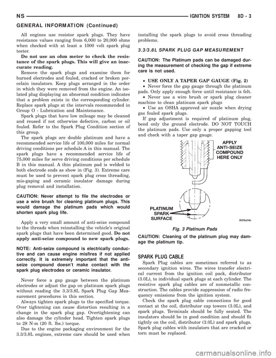
B in this manual. A thin platinum pad is welded to
both electrode ends as show in (Fig. 3). Extreme care
must be used to prevent spark plug cross threading,
mis-gaping and ceramic insulator damage during
plug removal and installation.
CAUTION: Never attempt to file the electrodes or
use a wire brush for cleaning platinum plugs. This
would damage the platinum pads which would
shorten spark plug life.
Apply a very small amount of anti-seize compound
to the threads when reinstalling the vehicle's original
spark plugs that have been determined good.Do not
apply anti-seize compound to new spark plugs.
NOTE: Anti-seize compound is electrically conduc-
tive and can cause engine misfires if not applied
correctly. It is extremely important that the anti-
seize compound doesn't make contact with the
spark plug electrodes or ceramic insulator.
Never force a gap gauge between the platinum
electrodes or adjust the gap on platinum spark plugs
without reading the 3.3/3.8L Spark Plug Gap Mea-
surement procedures in this section.
Always tighten spark plugs to the specified torque.
Over tightening can cause distortion resulting in a
change in the spark plug gap. Overtightening can
also damage the cylinder head. Tighten spark plugs
to 28 N´m (20 ft. lbs.) torque.
Due to the engine packaging environment for the
3.3/3.8L engines, extreme care should be used wheninstalling the spark plugs to avoid cross threading
problems.
3.3/3.8L SPARK PLUG GAP MEASUREMENT
CAUTION: The Platinum pads can be damaged dur-
ing the measurement of checking the gap if extreme
care is not used.
²USE ONLY A TAPER GAP GAUGE (Fig. 2)
²Never force the gap gauge through the platinum
pads. Only apply enough force until resistance is felt.
²Never use a wire brush or spark plug cleaner
machine to clean platinum spark plugs
²Use an OSHA approved air nozzle when drying
gas fouled spark plugs.
If gap adjustment is required of platinum plug,
bend only the ground electrode. DO NOT TOUCH
the platinum pads. Use only a proper gapping tool
and check with a taper gap gauge.
CAUTION: Cleaning of the platinum plug may dam-
age the platinum tip.
SPARK PLUG CABLE
Spark Plug cables are sometimes referred to as
secondary ignition wires. The wires transfer electri-
cal current from the ignition coil pack, distributor
(3.0L), to individual spark plugs at each cylinder. The
resistive spark plug cables are of nonmetallic con-
struction. The cables provide suppression of radio fre-
quency emissions from the ignition system.
Check the spark plug cable connections for good
contact at the coil, distributor cap towers (3.0L), and
spark plugs. Terminals should be fully seated. The
insulators should be in good condition and should fit
tightly on the coil, distributor (3.0L) and spark plugs.
Spark plug cables with insulators that are cracked or
torn must be replaced.
Fig. 3 Platinum Pads
NSIGNITION SYSTEM 8D - 3
GENERAL INFORMATION (Continued)
Page 305 of 1938

THROTTLE POSITION SENSOR (TPS)
The TPS mounts to the side of the throttle body
(Fig. 13).
The TPS connects to the throttle blade shaft. The
TPS is a variable resistor that provides the Power-
train Control Module (PCM) with an input signal
(voltage). The signal represents throttle blade posi-
tion. As the position of the throttle blade changes,
the resistance of the TPS changes.
The PCM supplies approximately 5 volts to the
TPS. The TPS output voltage (input signal to the
powertrain control module) represents throttle blade
position. The TPS output voltage to the PCM varies
from approximately 0.40 volt at minimum throttle
opening (idle) to a maximum of 3.80 volts at wide
open throttle.
Along with inputs from other sensors, the PCM
uses the TPS input to determine current engine oper-
ating conditions. The PCM also adjusts fuel injector
pulse width and ignition timing based on these
inputs.
LOCK KEY CYLINDER
The lock cylinder is inserted in the end of the
housing opposite the ignition switch. The ignition key
rotates the cylinder to 5 different detents (Fig. 14):
²Accessory
²Off (lock)
²Unlock
²On/Run
²Start
KNOCK SENSOR
The knock sensor threads into the side of the cyl-
inder block in front of the starter motor. When the
knock sensor detects a knock in one of the cylinders,
it sends an input signal to the PCM. In response, the
PCM retards ignition timing for all cylinders by a
scheduled amount.
Knock sensors contain a piezoelectric material
which constantly vibrates and sends an input voltage
(signal) to the PCM while the engine operates. As the
intensity of the crystal's vibration increase, the knock
sensor output voltage also increases.
Fig. 12 Engine Coolant Temperature SensorÐ3.3/
3.8LFig. 13 Throttle Position Sensor and Idle Air Control
Motor
Fig. 14 Ignition Lock Cylinder Detents
NSIGNITION SYSTEM 8D - 7
GENERAL INFORMATION (Continued)