instrument cluster CHRYSLER VOYAGER 2001 Service Manual
[x] Cancel search | Manufacturer: CHRYSLER, Model Year: 2001, Model line: VOYAGER, Model: CHRYSLER VOYAGER 2001Pages: 4284, PDF Size: 83.53 MB
Page 1842 of 4284
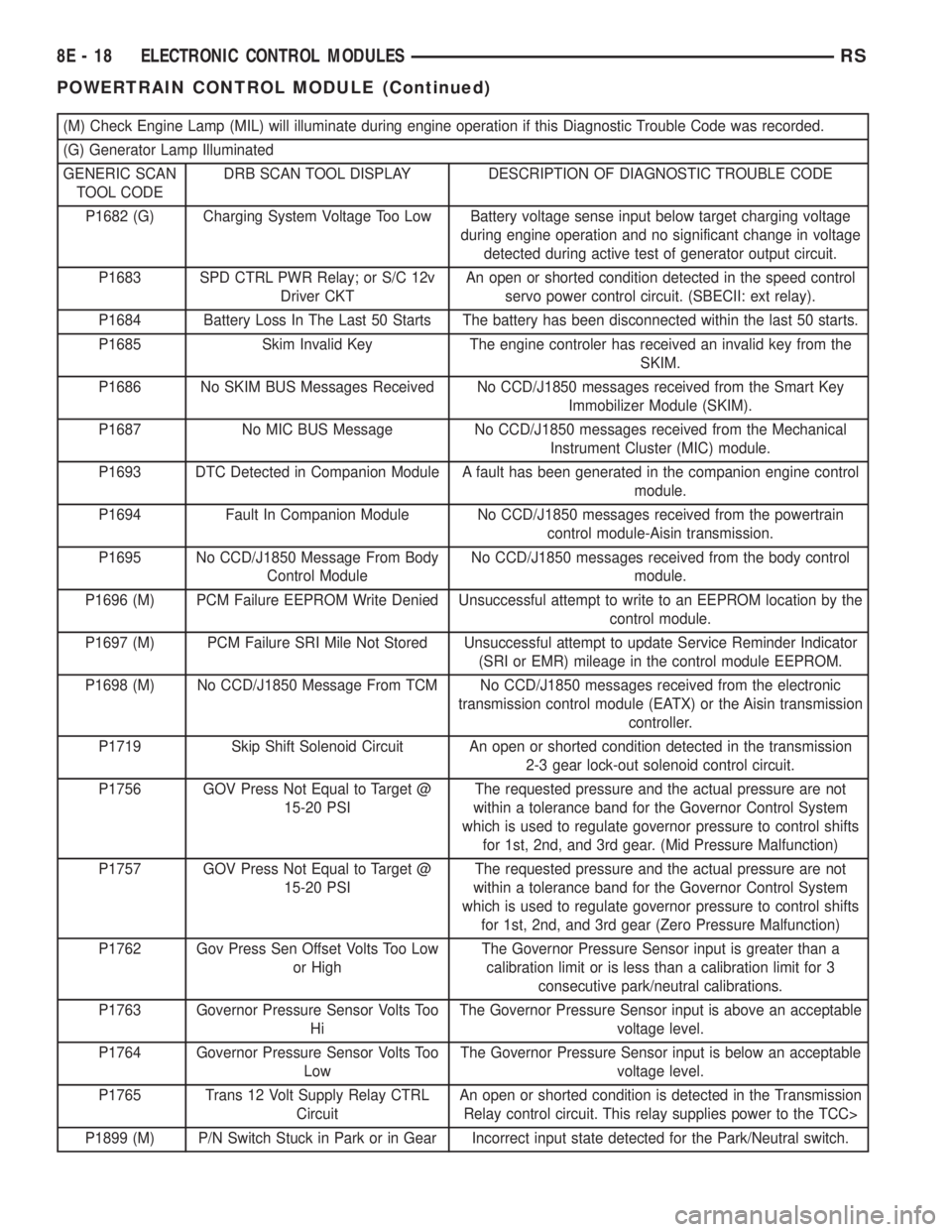
(M) Check Engine Lamp (MIL) will illuminate during engine operation if this Diagnostic Trouble Code was recorded.
(G) Generator Lamp Illuminated
GENERIC SCAN
TOOL CODEDRB SCAN TOOL DISPLAY DESCRIPTION OF DIAGNOSTIC TROUBLE CODE
P1682 (G) Charging System Voltage Too Low Battery voltage sense input below target charging voltage
during engine operation and no significant change in voltage
detected during active test of generator output circuit.
P1683 SPD CTRL PWR Relay; or S/C 12v
Driver CKTAn open or shorted condition detected in the speed control
servo power control circuit. (SBECII: ext relay).
P1684 Battery Loss In The Last 50 Starts The battery has been disconnected within the last 50 starts.
P1685 Skim Invalid Key The engine controler has received an invalid key from the
SKIM.
P1686 No SKIM BUS Messages Received No CCD/J1850 messages received from the Smart Key
Immobilizer Module (SKIM).
P1687 No MIC BUS Message No CCD/J1850 messages received from the Mechanical
Instrument Cluster (MIC) module.
P1693 DTC Detected in Companion Module A fault has been generated in the companion engine control
module.
P1694 Fault In Companion Module No CCD/J1850 messages received from the powertrain
control module-Aisin transmission.
P1695 No CCD/J1850 Message From Body
Control ModuleNo CCD/J1850 messages received from the body control
module.
P1696 (M) PCM Failure EEPROM Write Denied Unsuccessful attempt to write to an EEPROM location by the
control module.
P1697 (M) PCM Failure SRI Mile Not Stored Unsuccessful attempt to update Service Reminder Indicator
(SRI or EMR) mileage in the control module EEPROM.
P1698 (M) No CCD/J1850 Message From TCM No CCD/J1850 messages received from the electronic
transmission control module (EATX) or the Aisin transmission
controller.
P1719 Skip Shift Solenoid Circuit An open or shorted condition detected in the transmission
2-3 gear lock-out solenoid control circuit.
P1756 GOV Press Not Equal to Target @
15-20 PSIThe requested pressure and the actual pressure are not
within a tolerance band for the Governor Control System
which is used to regulate governor pressure to control shifts
for 1st, 2nd, and 3rd gear. (Mid Pressure Malfunction)
P1757 GOV Press Not Equal to Target @
15-20 PSIThe requested pressure and the actual pressure are not
within a tolerance band for the Governor Control System
which is used to regulate governor pressure to control shifts
for 1st, 2nd, and 3rd gear (Zero Pressure Malfunction)
P1762 Gov Press Sen Offset Volts Too Low
or HighThe Governor Pressure Sensor input is greater than a
calibration limit or is less than a calibration limit for 3
consecutive park/neutral calibrations.
P1763 Governor Pressure Sensor Volts Too
HiThe Governor Pressure Sensor input is above an acceptable
voltage level.
P1764 Governor Pressure Sensor Volts Too
LowThe Governor Pressure Sensor input is below an acceptable
voltage level.
P1765 Trans 12 Volt Supply Relay CTRL
CircuitAn open or shorted condition is detected in the Transmission
Relay control circuit. This relay supplies power to the TCC>
P1899 (M) P/N Switch Stuck in Park or in Gear Incorrect input state detected for the Park/Neutral switch.
8E - 18 ELECTRONIC CONTROL MODULESRS
POWERTRAIN CONTROL MODULE (Continued)
Page 1869 of 4284
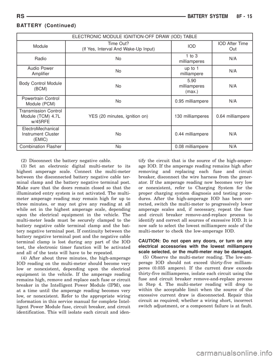
ELECTRONIC MODULE IGNITION-OFF DRAW (IOD) TABLE
ModuleTime Out?
(If Yes, Interval And Wake-Up Input)IODIOD After Time
Out
Radio No1to3
milliamperesN/A
Audio Power
AmplifierNoup to 1
milliampereN/A
Body Control Module
(BCM)No5.90
milliamperes
(max.)N/A
Powertrain Control
Module (PCM)No 0.95 milliampere N/A
Transmission Control
Module (TCM) 4.7L
w/45RFEYES (20 minutes, ignition on) 130 milliamperes 0.64 milliampere
ElectroMechanical
Instrument Cluster
(EMIC)No 0.44 milliampere N/A
Combination Flasher No 0.08 milliampere N/A
(2) Disconnect the battery negative cable.
(3) Set an electronic digital multi-meter to its
highest amperage scale. Connect the multi-meter
between the disconnected battery negative cable ter-
minal clamp and the battery negative terminal post.
Make sure that the doors remain closed so that the
illuminated entry system is not activated. The multi-
meter amperage reading may remain high for up to
three minutes, or may not give any reading at all
while set in the highest amperage scale, depending
upon the electrical equipment in the vehicle. The
multi-meter leads must be securely clamped to the
battery negative cable terminal clamp and the bat-
tery negative terminal post. If continuity between the
battery negative terminal post and the negative cable
terminal clamp is lost during any part of the IOD
test, the electronic timer function will be activated
and all of the tests will have to be repeated.
(4) After about three minutes, the high-amperage
IOD reading on the multi-meter should become very
low or nonexistent, depending upon the electrical
equipment in the vehicle. If the amperage reading
remains high, remove and replace each fuse or circuit
breaker in the Intelligent Power Module (IPM), one
at a time until the amperage reading becomes very
low, or nonexistent. Refer to the appropriate wiring
information in this service manual for complete Intel-
ligent Power Module fuse, circuit breaker, and circuit
identification. This will isolate each circuit and iden-tify the circuit that is the source of the high-amper-
age IOD. If the amperage reading remains high after
removing and replacing each fuse and circuit
breaker, disconnect the wire harness from the gener-
ator. If the amperage reading now becomes very low
or nonexistent, refer to Charging System for the
proper charging system diagnosis and testing proce-
dures. After the high-amperage IOD has been cor-
rected, switch the multi-meter to progressively lower
amperage scales and, if necessary, repeat the fuse
and circuit breaker remove-and-replace process to
identify and correct all sources of excessive IOD. It is
now safe to select the lowest milliampere scale of the
multi-meter to check the low-amperage IOD.
CAUTION: Do not open any doors, or turn on any
electrical accessories with the lowest milliampere
scale selected, or the multi-meter may be damaged.
(5) Observe the multi-meter reading. The low-am-
perage IOD should not exceed thirty-five milliam-
peres (0.035 ampere). If the current draw exceeds
thirty-five milliamperes, isolate each circuit using the
fuse and circuit breaker remove-and-replace process
in Step 4. The multi-meter reading will drop to
within the acceptable limit when the source of the
excessive current draw is disconnected. Repair this
circuit as required; whether a wiring short, incorrect
switch adjustment, or a component failure is at fault.
RSBATTERY SYSTEM8F-15
BATTERY (Continued)
Page 1875 of 4284

CHARGING
TABLE OF CONTENTS
page page
CHARGING
DESCRIPTION...........................21
OPERATION.............................21
DIAGNOSIS AND TESTING.................22
ON-BOARD DIAGNOSTIC SYSTEM.........22
SPECIFICATIONS........................22
SPECIAL TOOLS.........................23
BATTERY TEMPERATURE SENSOR
DESCRIPTION...........................23
OPERATION.............................23
REMOVAL..............................23
GENERATOR
DESCRIPTION...........................23
OPERATION.............................23REMOVAL..............................23
INSTALLATION...........................24
GENERATOR DECOUPLER PULLEY
DESCRIPTION...........................25
OPERATION.............................25
DIAGNOSIS AND TESTING.................25
GENERATOR DECOUPLER...............25
REMOVAL..............................25
INSTALLATION...........................26
VOLTAGE REGULATOR
DESCRIPTION...........................26
OPERATION.............................26
REMOVAL..............................26
CHARGING
DESCRIPTION - CHARGING SYSTEM
The charging system consists of:
²Generator
²Decoupler Pulley (If equipped)
²Electronic Voltage Regulator (EVR) circuitry
within the Powertrain Control Module (PCM)
²Ignition switch (refer to the Ignition System sec-
tion for information)
²Battery (refer to the Battery section for informa-
tion)
²Battery temperature sensor
²Voltmeter (refer to the Instrument Cluster sec-
tion for information)
²Wiring harness and connections (refer to the
Wiring section for information)
²Accessory drive belt (refer to the Cooling section
for more information)
OPERATION - CHARGING SYSTEM
The charging system is turned on and off with the
ignition switch. The system is on when the engine is
running and the ASD relay is energized. When the
ASD relay is on, voltage is supplied to the ASD relay
sense circuit at the PCM. This voltage is connected
through the PCM and supplied to one of the genera-
tor field terminals (Gen. Source +) at the back of the
generator.
The generator is driven by the engine through a
serpentine belt and pulley or decoupler pulley
arrangement.The amount of DC current produced by the gener-
ator is controlled by the EVR (field control) circuitry
contained within the PCM. This circuitry is con-
nected in series with the second rotor field terminal
and ground.
A battery temperature sensor is used to sense bat-
tery temperature. This temperature data, along with
data from monitored line voltage, is used by the PCM
to vary the battery charging rate. This is done by
cycling the ground path to control the strength of the
rotor magnetic field. The PCM then compensates and
regulates generator current output accordingly to
maintain system voltage at the targeted system volt-
age based on battery temperature.
All vehicles are equipped with On-Board Diagnos-
tics (OBD). All OBD-sensed systems, including EVR
(field control) circuitry, are monitored by the PCM.
Each monitored circuit is assigned a Diagnostic Trou-
ble Code (DTC). The PCM will store a DTC in elec-
tronic memory for certain failures it detects. Refer to
On-Board Diagnostics in the Electronic Control Mod-
ules(Refer to 8 - ELECTRICAL/ELECTRONIC CON-
TROL MODULES/POWERTRAIN CONTROL
MODULE - DESCRIPTION) section for more DTC
information.
The Check Gauges Lamp (if equipped) monitors:
charging system voltage,engine coolant tempera-
ture and engine oil pressure. If an extreme condition
is indicated, the lamp will be illuminated. This is
done as reminder to check the three gauges. The sig-
nal to activate the lamp is sent via the PCI bus cir-
cuits. The lamp is located on the instrument panel.
Refer to the Instrument Cluster section for additional
information.
RSCHARGING8F-21
Page 1927 of 4284
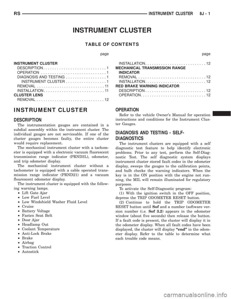
INSTRUMENT CLUSTER
TABLE OF CONTENTS
page page
INSTRUMENT CLUSTER
DESCRIPTION............................1
OPERATION.............................1
DIAGNOSIS AND TESTING..................1
INSTRUMENT CLUSTER..................1
REMOVAL..............................11
INSTALLATION...........................11
CLUSTER LENS
REMOVAL..............................12INSTALLATION...........................12
MECHANICAL TRANSMISSION RANGE
INDICATOR
REMOVAL..............................12
INSTALLATION...........................12
RED BRAKE WARNING INDICATOR
DESCRIPTION...........................12
OPERATION.............................12
INSTRUMENT CLUSTER
DESCRIPTION
The instrumentation gauges are contained in a
subdial assembly within the instrument cluster. The
individual gauges are not serviceable. If one of the
cluster gauges becomes faulty, the entire cluster
would require replacement.
The mechanical instrument cluster with a tachom-
eter is equipped with a electronic vacuum fluorescent
transmission range indicator (PRND3L), odometer,
and trip odometer display.
The mechanical instrument cluster without a
tachometer is equipped with a cable operated trans-
mission range indicator (PRND21) and a vacuum
flourescent odometer display.
The instrument cluster is equipped with the follow-
ing warning lamps.
²Lift Gate Ajar
²Low Fuel Level
²Low Windshield Washer Fluid Level
²Cruise
²Battery Voltage
²Fasten Seat Belt
²Door Ajar
²Headlamp Out
²Coolant Temperature
²Anti-Lock Brake
²Brake
²Airbag
²Traction Control
²Autostick
OPERATION
Refer to the vehicle Owner's Manual for operation
instructions and conditions for the Instrument Clus-
ter Gauges.
DIAGNOSIS AND TESTING - SELF-
DIAGNOSTICS
The instrument clusters are equipped with a self
diagnostic test feature to help identify electronic
problems. Prior to any test, perform the Self-Diag-
nostic Test. The self diagnostic system displays
instrument cluster stored fault codes in the odometer
display, sweeps the gauges to the calibration points,
and bulb checks the warning indicators. When the
key is in the ON position with the engine not run-
ning, the MIL will remain illuminated for regulatory
purposes.
To activate the Self-Diagnostic program:
(1) With the ignition switch in the OFF position,
depress the TRIP ODOMETER RESET button.
(2) Continue to hold the TRIP ODOMETER
RESET button untilSofand a number (software ver-
sion number (i.e.Sof 3.2) appears in the odometer
window (about five seconds) then release the button.
If a fault code is present, the cluster will display it in
the odometer display. When all fault codes have been
displayed, the cluster will displayªendºin the odom-
eter display. Refer to the table to determine what
each trouble code means.
RSINSTRUMENT CLUSTER8J-1
Page 1928 of 4284

INSTRUMENT CLUSTER DTC'S
DTC DESCRIPTION
100.00 LOOP-BACK FAILURE
100.1 ABS COMMUNICATION FAULT
100.2 BCM COMMUNICATION FAULT
100.3 EATX COMMUNICATION FAULT
100.4 PCM COMMUNICATION FAULT
100.5 ORC COMMUNICATION FAULT
100.6 SBEC/DEC/MCM COMMUNICATION
FAULT
200.0 AIRBAG LED SHORT
200.1 AIRBAG LED OPEN
200.2 ABS LED SHORT
200.3 ABS LED OPEN
200.6 EL INVERTER TIME-OUT
200.7 EATX MISMATCH
DIM TEST
When CHEC-0 is displayed in the odometer win-
dow, the cluster's Vacuum Fluorescent (VF) displays
will dim down. If the VF display brightness does not
change, a problem exists in the cluster.
CALIBRATION TEST
When CHEC-1 is displayed in the odometer win-
dow, each of the cluster's gauge pointers will move
sequentially through each calibration point. The
table contains the proper calibration points for each
gauge. If the gauge pointers are not calibrated, a
problem exists in the cluster. If any gauge is out of
calibration, replace the cluster.
CLUSTER CALIBRATION
SPEEDOMETER CALIBRATION POINT
1 0 MPH (0 KM/H)
2 20 MPH (40 KM/H)
3 60 MPH (100 KM/H)
4 100 MPH (160 KM/H)
TACHOMETER
1 0 RPM
2 1000 RPM
3 3000 RPM
4 6000 RPM
FUEL GAUGE
1 EMPTY
2 1/4 FILLED
3 1/2 FILLED
4 FULL
TEMPERATURE
GAUGE
1 COLD
2 1/4
3 3/4
4 HOT
ODOMETER SEGMENT TEST
When CHEC-2 is displayed in the odometer win-
dow, each digit of the odometer will illuminate
sequentially. If a segment in the odometer does not
illuminate normally, a problem exists in the display.
ELECTRONIC TRANSMISSION RANGE INDICATOR
SEGMENT TEST
When CHEC-3 is displayed in the odometer win-
dow, each segment of the transmission range indica-
tor will illuminate sequentially. If a segment in the
transmission range indicator does not illuminate nor-
mally, a problem exists in the display board.
8J - 2 INSTRUMENT CLUSTERRS
INSTRUMENT CLUSTER (Continued)
Page 1929 of 4284

CONDITIONS
Refer to the following tables for possible problems,
causes, and corrections.
²INSTRUMENT CLUSTER
²SPEEDOMETER DIAGNOSIS
²TACHOMETER DIAGNOSIS
²FUEL GAUGE DIAGNOSIS
²TEMPERATURE GAUGE DIAGNOSIS²ODOMETER DIAGNOSIS
²ELECTRONIC GEAR INDICATOR DISPLAY
DIAGNOSIS
²MECHANICAL TRANSMISSION RANGE INDI-
CATOR (PRND21) DIAGNOSIS
NOTE: Always check the functionality of the cluster
by running the self test prior to troubleshooting.
INSTRUMENT CLUSTER
CONDITION POSSIBLE CAUSES CORRECTION
INSTRUMENT CLUSTER
INOPERATIVE.
NO RESPONSE FROM
INSTRUMENT CLUSTER.NO PCI BUS MESSAGES
FROM THE BCM.1. USE A DRB IIITSCAN TOOL TO CHECK THE
BCM. IF OK, LOOK FOR ANOTHER POSSIBLE
CAUSE FOR CLUSTER FAILURE. IF NOT OK,
REFER TO THE PROPER BODY DIAGNOSTIC
PROCEDURES MANUAL.
SPREAD TERMINAL(S)
ON WIRING HARNESS
CLUSTER CONNECTOR.1. REMOVE CLUSTER FROM INSTRUMENT PANEL
AND CHECK WIRING HARNESS CONNECTOR FOR
SPREAD TERMINAL. IF OK, LOOK FOR ANOTHER
POSSIBLE CAUSE FOR THE CLUSTER FAILURE. IF
NOT OK, REPAIR CONNECTOR.
BCM IS NOT RECEIVING
PROPER INPUT FROM
THE IGNITION SWITCH.1. USE A DRB IIITSCAN TOOL TO VERIFY IGNITION
SWITCH STATUS INTO THE BCM. IF NOT OK, GO
TO STEP (2). IF OK, LOOK AT ANOTHER POSSIBLE
CAUSE OF FAILURE.
2. CHECK IGNITION SWITCH FUNCTION AND
WIRING.
INTERNAL CLUSTER
FAILURE.1. REPLACE CLUSTER.
WAKE UP CIRCUIT
FAULTY.VERIFY CONTINUITY OF WAKE UP CIRCUIT FROM
BCM TO MIC. CIRCUIT SHALL BE LOW WHENEVER
BCM IS AWAKE.
POWER OR GROUND
MISSING.IF NO RESPONSE FROM THE MIC, CHECK FOR
POWER AND GROUND AT THE MIC CONNECTOR.
REFER TO WIRING DIAGRAMS FOR CONNECTOR
CALL OUTS.
RSINSTRUMENT CLUSTER8J-3
INSTRUMENT CLUSTER (Continued)
Page 1930 of 4284
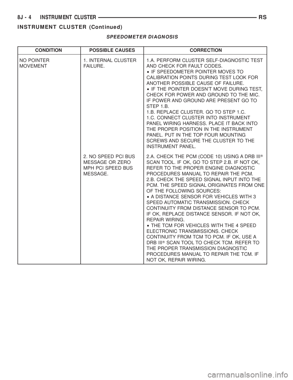
SPEEDOMETER DIAGNOSIS
CONDITION POSSIBLE CAUSES CORRECTION
NO POINTER
MOVEMENT1. INTERNAL CLUSTER
FAILURE.1.A. PERFORM CLUSTER SELF-DIAGNOSTIC TEST
AND CHECK FOR FAULT CODES.
²IF SPEEDOMETER POINTER MOVES TO
CALIBRATION POINTS DURING TEST LOOK FOR
ANOTHER POSSIBLE CAUSE OF FAILURE.
²IF THE POINTER DOESN'T MOVE DURING TEST,
CHECK FOR POWER AND GROUND TO THE MIC.
IF POWER AND GROUND ARE PRESENT GO TO
STEP 1.B.
1.B. REPLACE CLUSTER. GO TO STEP 1.C.
1.C. CONNECT CLUSTER INTO INSTRUMENT
PANEL WIRING HARNESS. PLACE IT BACK INTO
THE PROPER POSITION IN THE INSTRUMENT
PANEL. PUT IN THE TOP FOUR MOUNTING
SCREWS AND SECURE THE CLUSTER TO THE
INSTRUMENT PANEL.
2. NO SPEED PCI BUS
MESSAGE OR ZERO
MPH PCI SPEED BUS
MESSAGE.2.A. CHECK THE PCM (CODE 10) USING A DRB IIIT
SCAN TOOL. IF OK, GO TO STEP 2.B. IF NOT OK,
REFER TO THE PROPER ENGINE DIAGNOSTIC
PROCEDURES MANUAL TO REPAIR THE PCM.
2.B. CHECK THE SPEED SIGNAL INPUT INTO THE
PCM. THE SPEED SIGNAL ORIGINATES FROM ONE
OF THE FOLLOWING SOURCES:
²A DISTANCE SENSOR FOR VEHICLES WITH 3
SPEED AUTOMATIC TRANSMISSION. CHECK
CONTINUITY FROM DISTANCE SENSOR TO PCM.
IF OK, REPLACE DISTANCE SENSOR. IF NOT OK,
REPAIR WIRING.
²THE TCM FOR VEHICLES WITH THE 4 SPEED
ELECTRONIC TRANSMISSIONS. CHECK
CONTINUITY FROM TCM TO PCM. IF OK, USE A
DRB IIITSCAN TOOL TO CHECK TCM. REFER TO
THE PROPER TRANSMISSION DIAGNOSTIC
PROCEDURES MANUAL TO REPAIR THE TCM. IF
NOT OK, REPAIR WIRING.
8J - 4 INSTRUMENT CLUSTERRS
INSTRUMENT CLUSTER (Continued)
Page 1931 of 4284
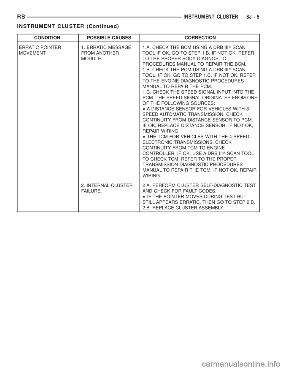
CONDITION POSSIBLE CAUSES CORRECTION
ERRATIC POINTER
MOVEMENT1. ERRATIC MESSAGE
FROM ANOTHER
MODULE.1.A. CHECK THE BCM USING A DRB IIITSCAN
TOOL IF OK, GO TO STEP 1.B. IF NOT OK, REFER
TO THE PROPER BODY DIAGNOSTIC
PROCEDURES MANUAL TO REPAIR THE BCM.
1.B. CHECK THE PCM USING A DRB IIITSCAN
TOOL. IF OK, GO TO STEP 1.C. IF NOT OK, REFER
TO THE ENGINE DIAGNOSTIC PROCEDURES
MANUAL TO REPAIR THE PCM.
1.C. CHECK THE SPEED SIGNAL INPUT INTO THE
PCM. THE SPEED SIGNAL ORIGINATES FROM ONE
OF THE FOLLOWING SOURCES:
²A DISTANCE SENSOR FOR VEHICLES WITH 3
SPEED AUTOMATIC TRANSMISSION. CHECK
CONTINUITY FROM DISTANCE SENSOR TO PCM.
IF OK, REPLACE DISTANCE SENSOR. IF NOT OK,
REPAIR WIRING.
²THE TCM FOR VEHICLES WITH THE 4 SPEED
ELECTRONIC TRANSMISSIONS. CHECK
CONTINUITY FROM TCM TO ENGINE
CONTROLLER. IF OK, USE A DRB IIITSCAN TOOL
TO CHECK TCM. REFER TO THE PROPER
TRANSMISSION DIAGNOSTIC PROCEDURES
MANUAL TO REPAIR THE TCM. IF NOT OK, REPAIR
WIRING.
2. INTERNAL CLUSTER
FAILURE.2.A. PERFORM CLUSTER SELF-DIAGNOSTIC TEST
AND CHECK FOR FAULT CODES.
²IF THE POINTER MOVES DURING TEST BUT
STILL APPEARS ERRATIC, THEN GO TO STEP 2.B.
2.B. REPLACE CLUSTER ASSEMBLY.
RSINSTRUMENT CLUSTER8J-5
INSTRUMENT CLUSTER (Continued)
Page 1932 of 4284
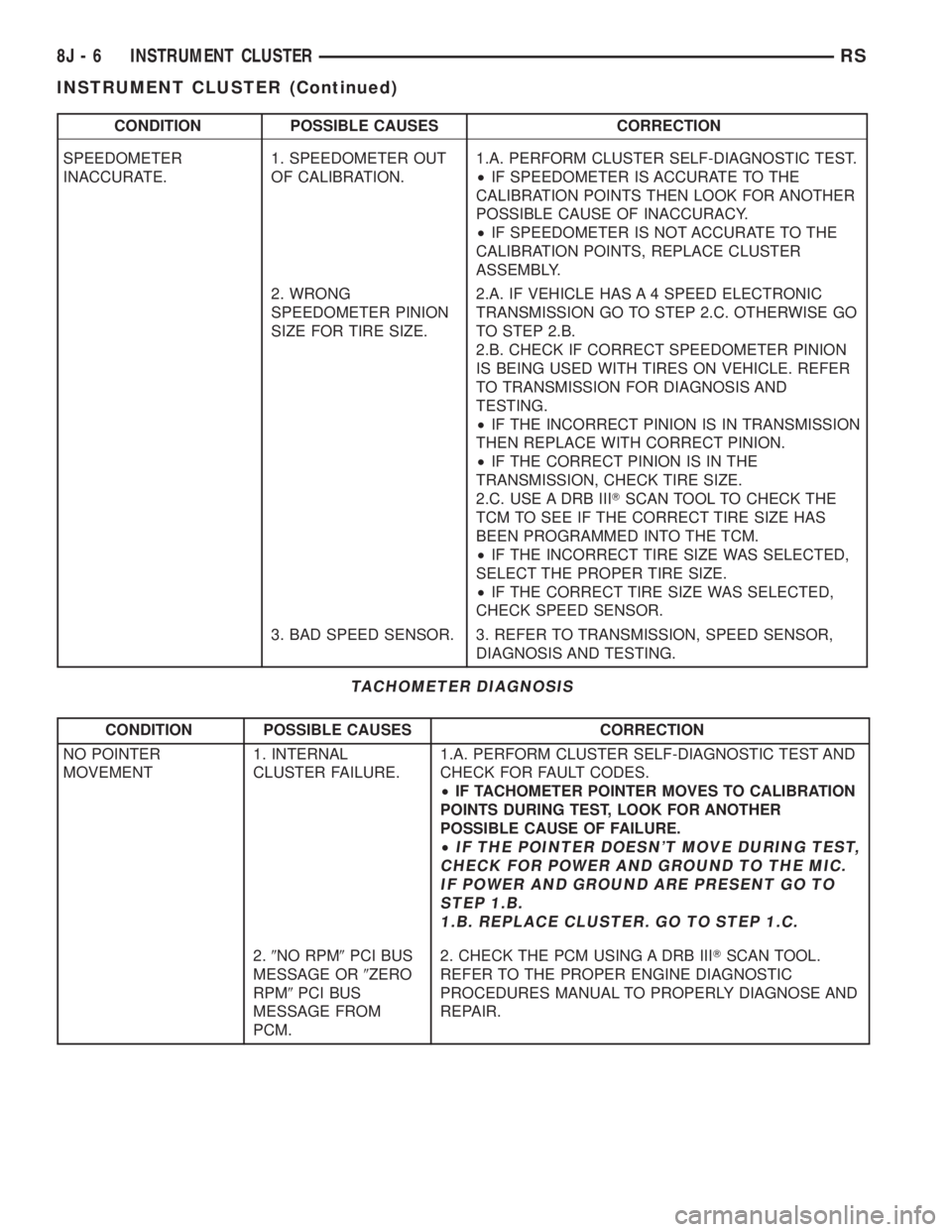
CONDITION POSSIBLE CAUSES CORRECTION
SPEEDOMETER
INACCURATE.1. SPEEDOMETER OUT
OF CALIBRATION.1.A. PERFORM CLUSTER SELF-DIAGNOSTIC TEST.
²IF SPEEDOMETER IS ACCURATE TO THE
CALIBRATION POINTS THEN LOOK FOR ANOTHER
POSSIBLE CAUSE OF INACCURACY.
²IF SPEEDOMETER IS NOT ACCURATE TO THE
CALIBRATION POINTS, REPLACE CLUSTER
ASSEMBLY.
2. WRONG
SPEEDOMETER PINION
SIZE FOR TIRE SIZE.2.A. IF VEHICLE HAS A 4 SPEED ELECTRONIC
TRANSMISSION GO TO STEP 2.C. OTHERWISE GO
TO STEP 2.B.
2.B. CHECK IF CORRECT SPEEDOMETER PINION
IS BEING USED WITH TIRES ON VEHICLE. REFER
TO TRANSMISSION FOR DIAGNOSIS AND
TESTING.
²IF THE INCORRECT PINION IS IN TRANSMISSION
THEN REPLACE WITH CORRECT PINION.
²IF THE CORRECT PINION IS IN THE
TRANSMISSION, CHECK TIRE SIZE.
2.C. USE A DRB IIITSCAN TOOL TO CHECK THE
TCM TO SEE IF THE CORRECT TIRE SIZE HAS
BEEN PROGRAMMED INTO THE TCM.
²IF THE INCORRECT TIRE SIZE WAS SELECTED,
SELECT THE PROPER TIRE SIZE.
²IF THE CORRECT TIRE SIZE WAS SELECTED,
CHECK SPEED SENSOR.
3. BAD SPEED SENSOR. 3. REFER TO TRANSMISSION, SPEED SENSOR,
DIAGNOSIS AND TESTING.
TACHOMETER DIAGNOSIS
CONDITION POSSIBLE CAUSES CORRECTION
NO POINTER
MOVEMENT1. INTERNAL
CLUSTER FAILURE.1.A. PERFORM CLUSTER SELF-DIAGNOSTIC TEST AND
CHECK FOR FAULT CODES.
²IF TACHOMETER POINTER MOVES TO CALIBRATION
POINTS DURING TEST, LOOK FOR ANOTHER
POSSIBLE CAUSE OF FAILURE.
²
IF THE POINTER DOESN'T MOVE DURING TEST,
CHECK FOR POWER AND GROUND TO THE MIC.
IF POWER AND GROUND ARE PRESENT GO TO
STEP 1.B.
1.B. REPLACE CLUSTER. GO TO STEP 1.C.
2.9NO RPM9PCI BUS
MESSAGE OR9ZERO
RPM9PCI BUS
MESSAGE FROM
PCM.2. CHECK THE PCM USING A DRB IIITSCAN TOOL.
REFER TO THE PROPER ENGINE DIAGNOSTIC
PROCEDURES MANUAL TO PROPERLY DIAGNOSE AND
REPAIR.
8J - 6 INSTRUMENT CLUSTERRS
INSTRUMENT CLUSTER (Continued)
Page 1933 of 4284
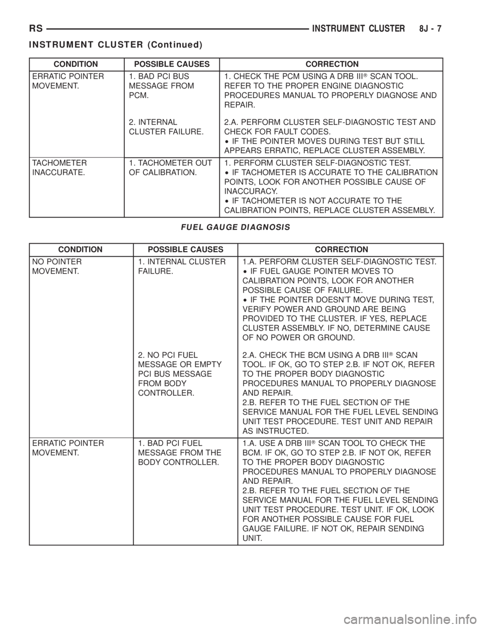
CONDITION POSSIBLE CAUSES CORRECTION
ERRATIC POINTER
MOVEMENT.1. BAD PCI BUS
MESSAGE FROM
PCM.1. CHECK THE PCM USING A DRB IIITSCAN TOOL.
REFER TO THE PROPER ENGINE DIAGNOSTIC
PROCEDURES MANUAL TO PROPERLY DIAGNOSE AND
REPAIR.
2. INTERNAL
CLUSTER FAILURE.2.A. PERFORM CLUSTER SELF-DIAGNOSTIC TEST AND
CHECK FOR FAULT CODES.
²IF THE POINTER MOVES DURING TEST BUT STILL
APPEARS ERRATIC, REPLACE CLUSTER ASSEMBLY.
TACHOMETER
INACCURATE.1. TACHOMETER OUT
OF CALIBRATION.1. PERFORM CLUSTER SELF-DIAGNOSTIC TEST.
²IF TACHOMETER IS ACCURATE TO THE CALIBRATION
POINTS, LOOK FOR ANOTHER POSSIBLE CAUSE OF
INACCURACY.
²IF TACHOMETER IS NOT ACCURATE TO THE
CALIBRATION POINTS, REPLACE CLUSTER ASSEMBLY.
FUEL GAUGE DIAGNOSIS
CONDITION POSSIBLE CAUSES CORRECTION
NO POINTER
MOVEMENT.1. INTERNAL CLUSTER
FAILURE.1.A. PERFORM CLUSTER SELF-DIAGNOSTIC TEST.
²IF FUEL GAUGE POINTER MOVES TO
CALIBRATION POINTS, LOOK FOR ANOTHER
POSSIBLE CAUSE OF FAILURE.
²IF THE POINTER DOESN'T MOVE DURING TEST,
VERIFY POWER AND GROUND ARE BEING
PROVIDED TO THE CLUSTER. IF YES, REPLACE
CLUSTER ASSEMBLY. IF NO, DETERMINE CAUSE
OF NO POWER OR GROUND.
2. NO PCI FUEL
MESSAGE OR EMPTY
PCI BUS MESSAGE
FROM BODY
CONTROLLER.2.A. CHECK THE BCM USING A DRB IIITSCAN
TOOL. IF OK, GO TO STEP 2.B. IF NOT OK, REFER
TO THE PROPER BODY DIAGNOSTIC
PROCEDURES MANUAL TO PROPERLY DIAGNOSE
AND REPAIR.
2.B. REFER TO THE FUEL SECTION OF THE
SERVICE MANUAL FOR THE FUEL LEVEL SENDING
UNIT TEST PROCEDURE. TEST UNIT AND REPAIR
AS INSTRUCTED.
ERRATIC POINTER
MOVEMENT.1. BAD PCI FUEL
MESSAGE FROM THE
BODY CONTROLLER.1.A. USE A DRB IIITSCAN TOOL TO CHECK THE
BCM. IF OK, GO TO STEP 2.B. IF NOT OK, REFER
TO THE PROPER BODY DIAGNOSTIC
PROCEDURES MANUAL TO PROPERLY DIAGNOSE
AND REPAIR.
2.B. REFER TO THE FUEL SECTION OF THE
SERVICE MANUAL FOR THE FUEL LEVEL SENDING
UNIT TEST PROCEDURE. TEST UNIT. IF OK, LOOK
FOR ANOTHER POSSIBLE CAUSE FOR FUEL
GAUGE FAILURE. IF NOT OK, REPAIR SENDING
UNIT.
RSINSTRUMENT CLUSTER8J-7
INSTRUMENT CLUSTER (Continued)