engine CHRYSLER VOYAGER 2001 Service Manual
[x] Cancel search | Manufacturer: CHRYSLER, Model Year: 2001, Model line: VOYAGER, Model: CHRYSLER VOYAGER 2001Pages: 4284, PDF Size: 83.53 MB
Page 1010 of 4284

TEST ACTION APPLICABILITY
3 Turn the ignition off to the lock position.
Disconnect the Rear Wiper Motor harness connector.
Note: Check connectors - Clean/repair as necessary.
Ignition on, engine not running.
Using a 12-volt test light connected to ground, check the Rear Wiper Motor Control
circuit in the Rear Wiper Motor harness connector.
NOTE: The test light must illuminate brightly. Compare the brightness to
that of a direct connection to the battery.
Turn ON the Rear Wiper Motor.
Does the test light illuminate brightly?All
Ye s®Go To 4
No®Go To 5
4 Turn the ignition off to the lock position.
Disconnect the Rear Wiper Motor harness connector.
Note: Check connectors - Clean/repair as necessary.
Ignition on, engine not running.
Using a 12-volt test light connected to 12 Volts, check the Rear Wiper Motor ground
circuit in the Rear Wiper Motor harness connector.
NOTE: The test light must illuminate brightly. Compare the brightness to
that of a direct connection to the battery.
Does the test light illuminate brightly?All
Ye s®Replace the Rear Wiper Motor in accordance with the Service
Information.
Perform BODY VERIFICATION TEST - VER 1.
No®Repair the Rear Wiper Motor ground circuit for an open.
Perform BODY VERIFICATION TEST - VER 1.
5 Turn the ignition off to the lock position.
Disconnect the Body Control Module harness connector.
Disconnect the Rear Wiper Motor harness connector.
Note: Check connectors - Clean/repair as necessary.
Measure the resistance of the Rear Wiper Motor Control Circuit from the Body
Control Module harness connector to the Rear Wiper Motor harness connector.
Is the resistance above 5.0 ohms?All
Ye s®Repair the Rear Wiper Motor Control Circuit for an open.
Perform BODY VERIFICATION TEST - VER 1.
No®Go To 6
6 Turn the ignition off to the lock position.
Disconnect the Body Control Module harness connector.
Disconnect the Rear Wiper Motor harness connector.
Note: Check connectors - Clean/repair as necessary.
Turn the ignition on.
Using a 12-volt test light connected to ground, check the Rear Wiper Motor Control
circuit.
Is the test light on?All
Ye s®Repair the Rear Wiper Motor Control Circuit for a short to
voltage.
Perform BODY VERIFICATION TEST - VER 1.
No®Replace the Body Control Module in accordance with the Service
Information.
Perform BODY VERIFICATION TEST - VER 1.
981
WINDSHIELD WIPER & WASHER
REAR WIPER OUTPUT OPEN ÐContinued
Page 1011 of 4284

Symptom:
REAR WIPER OUTPUT SHORT TO GROUND
When Monitored and Set Condition:
REAR WIPER OUTPUT SHORT TO GROUND
When Monitored: Ignition ON
Set Condition:
POSSIBLE CAUSES
REAR WIPER MOTOR FUNCTION
INTERMITTENT WIRING AND CONNECTORS
REAR WIPER MOTOR CONTROL CIRCUIT SHORT TO GROUND
BODY CONTROL MODULE
TEST ACTION APPLICABILITY
1 Ignition on, engine not running.
Turn on the Rear Wiper.
Does the Rear Wiper Function?All
Ye s®Go To 2
No®Go To 3
2 Turn the ignition on.
With the DRBIIIt, erase all BCM and FCM DTCs.
Turn the ignition off.
The conditions necessary to set this DTC are not present at this time.
Using the schematics as a guide, inspect the wiring and connectors specific to this
circuit.
Wiggle the wiring while checking for shorts and open circuits.
Were there any problems found?All
Ye s®Repair as necessary.
Perform BODY VERIFICATION TEST - VER 1.
No®Test Complete.
3 Turn the ignition off to the lock position.
Disconnect the Body Control Module harness connector.
Disconnect the Rear Wiper Motor harness connector.
Note: Check connectors - Clean/repair as necessary.
Measure the resistance between ground and the Rear Wiper Motor Control circuit.
Is the resistance less than 5.0 ohms?All
Ye s®Repair the Rear Wiper Motor Control Circuit for a short to
ground.
Perform BODY VERIFICATION TEST - VER 1.
No®Go To 4
982
WINDSHIELD WIPER & WASHER
Page 1017 of 4284

Verification Tests
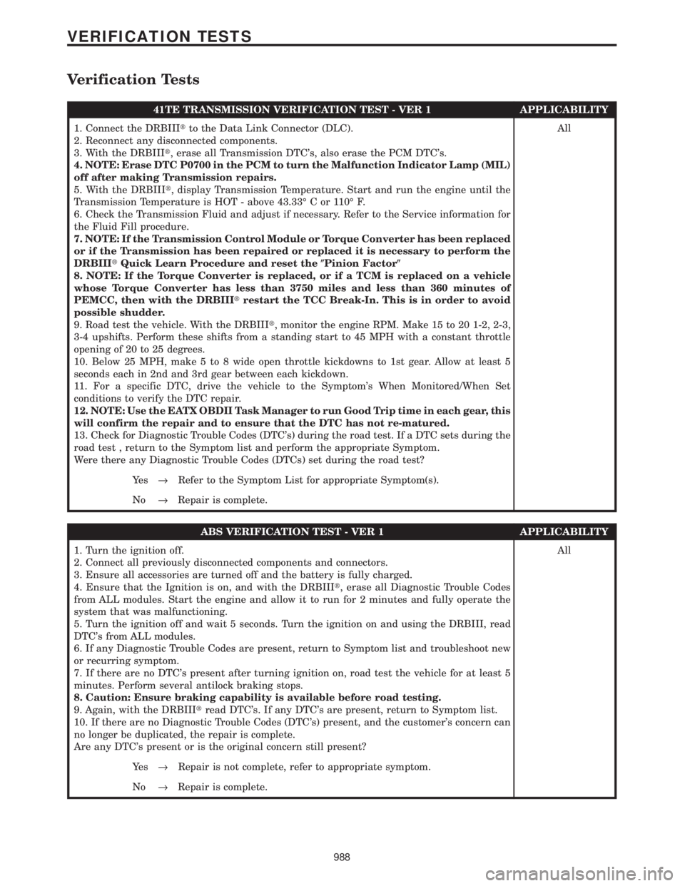
41TE TRANSMISSION VERIFICATION TEST - VER 1 APPLICABILITY
1. Connect the DRBIIItto the Data Link Connector (DLC).
2. Reconnect any disconnected components.
3. With the DRBIIIt, erase all Transmission DTC's, also erase the PCM DTC's.
4. NOTE: Erase DTC P0700 in the PCM to turn the Malfunction Indicator Lamp (MIL)
off after making Transmission repairs.
5. With the DRBIIIt, display Transmission Temperature. Start and run the engine until the
Transmission Temperature is HOT - above 43.33É C or 110É F.
6. Check the Transmission Fluid and adjust if necessary. Refer to the Service information for
the Fluid Fill procedure.
7. NOTE: If the Transmission Control Module or Torque Converter has been replaced
or if the Transmission has been repaired or replaced it is necessary to perform the
DRBIIItQuick Learn Procedure and reset the(Pinion Factor(
8. NOTE: If the Torque Converter is replaced, or if a TCM is replaced on a vehicle
whose Torque Converter has less than 3750 miles and less than 360 minutes of
PEMCC, then with the DRBIIItrestart the TCC Break-In. This is in order to avoid
possible shudder.
9. Road test the vehicle. With the DRBIIIt, monitor the engine RPM. Make 15 to 20 1-2, 2-3,
3-4 upshifts. Perform these shifts from a standing start to 45 MPH with a constant throttle
opening of 20 to 25 degrees.
10. Below 25 MPH, make 5 to 8 wide open throttle kickdowns to 1st gear. Allow at least 5
seconds each in 2nd and 3rd gear between each kickdown.
11. For a specific DTC, drive the vehicle to the Symptom's When Monitored/When Set
conditions to verify the DTC repair.
12. NOTE: Use the EATX OBDII Task Manager to run Good Trip time in each gear, this
will confirm the repair and to ensure that the DTC has not re-matured.
13. Check for Diagnostic Trouble Codes (DTC's) during the road test. If a DTC sets during the
road test , return to the Symptom list and perform the appropriate Symptom.
Were there any Diagnostic Trouble Codes (DTCs) set during the road test?All
Ye s®Refer to the Symptom List for appropriate Symptom(s).
No®Repair is complete.
ABS VERIFICATION TEST - VER 1 APPLICABILITY
1. Turn the ignition off.
2. Connect all previously disconnected components and connectors.
3. Ensure all accessories are turned off and the battery is fully charged.
4. Ensure that the Ignition is on, and with the DRBIIIt, erase all Diagnostic Trouble Codes
from ALL modules. Start the engine and allow it to run for 2 minutes and fully operate the
system that was malfunctioning.
5. Turn the ignition off and wait 5 seconds. Turn the ignition on and using the DRBIII, read
DTC's from ALL modules.
6. If any Diagnostic Trouble Codes are present, return to Symptom list and troubleshoot new
or recurring symptom.
7. If there are no DTC's present after turning ignition on, road test the vehicle for at least 5
minutes. Perform several antilock braking stops.
8. Caution: Ensure braking capability is available before road testing.
9. Again, with the DRBIIItread DTC's. If any DTC's are present, return to Symptom list.
10. If there are no Diagnostic Trouble Codes (DTC's) present, and the customer's concern can
no longer be duplicated, the repair is complete.
Are any DTC's present or is the original concern still present?All
Ye s®Repair is not complete, refer to appropriate symptom.
No®Repair is complete.
988
VERIFICATION TESTS
Page 1019 of 4284

BODY VERIFICATION TEST - VER 1 APPLICABILITY
1. Disconnect all jumper wires and reconnect all previously disconnected components and
connectors.
2. With the DRBIIIt, record and erase all DTCs from ALL modules. Cycle the ignition on then
off
3. If the Sentry Key Immobilizer Module (SKIM), the Powertrain Control Module (PCM), or the
Engine Control Module (ECM) was replaced, proceed to number 9. If the SKIM, PCM, or ECM
was not replaced, continue to the next number.
4. If the Body Control Module (BCM) was replaced, turn the ignition on for 15 seconds (to allow
the new BCM to learn VIN) or engine may not start (if VTSS equipped). If the vehicle is
equipped with VTSS, use the DRBIIItand enable VTSS.
5. Program all other options as needed.
6. If any actuators were replaced in the HVAC System, with the DRBIIItin HVAC, select
System Tests then select HVAC Door Recalibration (manual temperature system only).
7. If any actuators were replaced in the ATC System, with the DRBIIItin Automatic Temp
Control, select Miscellaneous then select Reset ATC Head.
8. If any repairs were made to the power sliding door or power liftgate, use the DRBIIItand
perform the open and close system tests. Observe the instructions on the DRBIIItscreen.
Proceed to number 16.
9. Obtain the vehicle's unique PIN assigned to it's original SKIM from either the vehicle's
invoice or from Chrysler's Customer Assistance Center (1-800-992-1997).
10. NOTE: Once Secured Access Mode is active, the SKIM will remain in that mode for 60
seconds.
11. With the DRBIIIt, select THEFT ALARM, SKIM, MISCELLANEOUS and select SKIM
REPLACED. Enter the 4 digit PIN to put the SKIM in Secured Access Mode.
12. The DRBIIItwill prompt for the following steps. (1) Program the country code into the
SKIM's memory. (2) Program the vehicle's VIN into the SKIM memory. (3) Transfer the
vehicle's Secret Key data from the PCM.
13. Using the DRBIIIt, program all customer keys into the SKIM memory. This requires that
the SKIM be in Secured Access Mode, using the 4 digit PIN.
14. Note: If the PCM or ECM is replaced, the VIN and the unique Secret Key data must be
transferred from the SKIM to the PCM or ECM. This procedure requires the SKIM to be placed
in Secured Access Mode using the 4-digit PIN.
15. Note: If 3 attempts are made to enter Secured Access Mode using an incorrect PIN, Secured
Access Mode will be locked out for 1 hour which causes the DRBIIItto display9No Resp from
SKIM9. To exit this mode, turn ignition to Run for 1 hour.
16. Ensure that all accessories are turned off and the battery is fully charged.
17. Start and run the engine for 2 minutes. Operate all functions of the system that caused the
original concern.
18. Turn the ignition off and wait 5 seconds. Turn the ignition on and using the DRBIIIt, read
DTCs from ALL modules.
Are any DTC's present or is the original condition still present?All
Ye s®Repair is not complete, refer to the appropriate symptom.
No®Repair is complete.
990
VERIFICATION TESTS
Verification Tests ÐContinued
Page 1020 of 4284

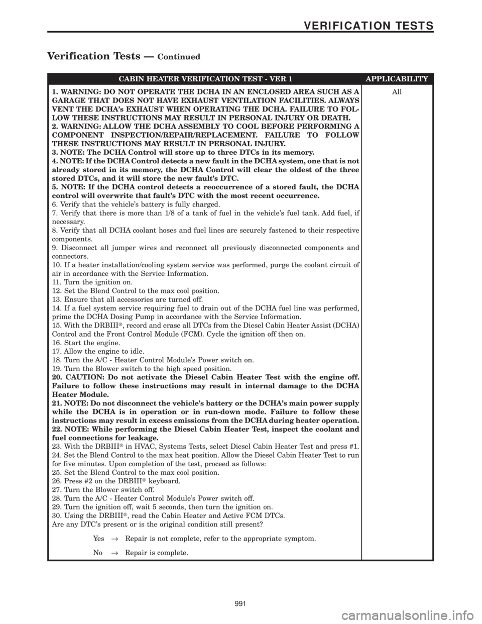
CABIN HEATER VERIFICATION TEST - VER 1 APPLICABILITY
1. WARNING: DO NOT OPERATE THE DCHA IN AN ENCLOSED AREA SUCH AS A
GARAGE THAT DOES NOT HAVE EXHAUST VENTILATION FACILITIES. ALWAYS
VENT THE DCHA's EXHAUST WHEN OPERATING THE DCHA. FAILURE TO FOL-
LOW THESE INSTRUCTIONS MAY RESULT IN PERSONAL INJURY OR DEATH.
2. WARNING: ALLOW THE DCHA ASSEMBLY TO COOL BEFORE PERFORMING A
COMPONENT INSPECTION/REPAIR/REPLACEMENT. FAILURE TO FOLLOW
THESE INSTRUCTIONS MAY RESULT IN PERSONAL INJURY.
3. NOTE: The DCHA Control will store up to three DTCs in its memory.
4. NOTE: If the DCHA Control detects a new fault in the DCHA system, one that is not
already stored in its memory, the DCHA Control will clear the oldest of the three
stored DTCs, and it will store the new fault's DTC.
5. NOTE: If the DCHA control detects a reoccurrence of a stored fault, the DCHA
control will overwrite that fault's DTC with the most recent occurrence.
6. Verify that the vehicle's battery is fully charged.
7. Verify that there is more than 1/8 of a tank of fuel in the vehicle's fuel tank. Add fuel, if
necessary.
8. Verify that all DCHA coolant hoses and fuel lines are securely fastened to their respective
components.
9. Disconnect all jumper wires and reconnect all previously disconnected components and
connectors.
10. If a heater installation/cooling system service was performed, purge the coolant circuit of
air in accordance with the Service Information.
11. Turn the ignition on.
12. Set the Blend Control to the max cool position.
13. Ensure that all accessories are turned off.
14. If a fuel system service requiring fuel to drain out of the DCHA fuel line was performed,
prime the DCHA Dosing Pump in accordance with the Service Information.
15. With the DRBIIIt, record and erase all DTCs from the Diesel Cabin Heater Assist (DCHA)
Control and the Front Control Module (FCM). Cycle the ignition off then on.
16. Start the engine.
17. Allow the engine to idle.
18. Turn the A/C - Heater Control Module's Power switch on.
19. Turn the Blower switch to the high speed position.
20. CAUTION: Do not activate the Diesel Cabin Heater Test with the engine off.
Failure to follow these instructions may result in internal damage to the DCHA
Heater Module.
21. NOTE: Do not disconnect the vehicle's battery or the DCHA's main power supply
while the DCHA is in operation or in run-down mode. Failure to follow these
instructions may result in excess emissions from the DCHA during heater operation.
22. NOTE: While performing the Diesel Cabin Heater Test, inspect the coolant and
fuel connections for leakage.
23. With the DRBIIItin HVAC, Systems Tests, select Diesel Cabin Heater Test and press #1.
24. Set the Blend Control to the max heat position. Allow the Diesel Cabin Heater Test to run
for five minutes. Upon completion of the test, proceed as follows:
25. Set the Blend Control to the max cool position.
26. Press #2 on the DRBIIItkeyboard.
27. Turn the Blower switch off.
28. Turn the A/C - Heater Control Module's Power switch off.
29. Turn the ignition off, wait 5 seconds, then turn the ignition on.
30. Using the DRBIIIt, read the Cabin Heater and Active FCM DTCs.
Are any DTC's present or is the original condition still present?All
Ye s®Repair is not complete, refer to the appropriate symptom.
No®Repair is complete.
991
VERIFICATION TESTS
Verification Tests ÐContinued
Page 1021 of 4284

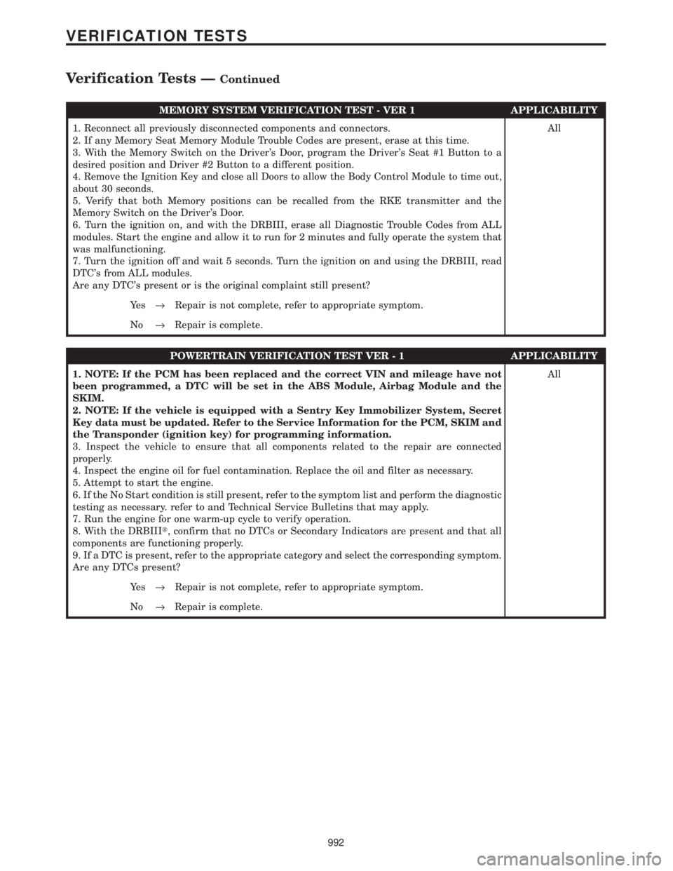
MEMORY SYSTEM VERIFICATION TEST - VER 1 APPLICABILITY
1. Reconnect all previously disconnected components and connectors.
2. If any Memory Seat Memory Module Trouble Codes are present, erase at this time.
3. With the Memory Switch on the Driver's Door, program the Driver's Seat #1 Button to a
desired position and Driver #2 Button to a different position.
4. Remove the Ignition Key and close all Doors to allow the Body Control Module to time out,
about 30 seconds.
5. Verify that both Memory positions can be recalled from the RKE transmitter and the
Memory Switch on the Driver's Door.
6. Turn the ignition on, and with the DRBIII, erase all Diagnostic Trouble Codes from ALL
modules. Start the engine and allow it to run for 2 minutes and fully operate the system that
was malfunctioning.
7. Turn the ignition off and wait 5 seconds. Turn the ignition on and using the DRBIII, read
DTC's from ALL modules.
Are any DTC's present or is the original complaint still present?All
Ye s®Repair is not complete, refer to appropriate symptom.
No®Repair is complete.
POWERTRAIN VERIFICATION TEST VER - 1 APPLICABILITY
1. NOTE: If the PCM has been replaced and the correct VIN and mileage have not
been programmed, a DTC will be set in the ABS Module, Airbag Module and the
SKIM.
2. NOTE: If the vehicle is equipped with a Sentry Key Immobilizer System, Secret
Key data must be updated. Refer to the Service Information for the PCM, SKIM and
the Transponder (ignition key) for programming information.
3. Inspect the vehicle to ensure that all components related to the repair are connected
properly.
4. Inspect the engine oil for fuel contamination. Replace the oil and filter as necessary.
5. Attempt to start the engine.
6. If the No Start condition is still present, refer to the symptom list and perform the diagnostic
testing as necessary. refer to and Technical Service Bulletins that may apply.
7. Run the engine for one warm-up cycle to verify operation.
8. With the DRBIIIt, confirm that no DTCs or Secondary Indicators are present and that all
components are functioning properly.
9. If a DTC is present, refer to the appropriate category and select the corresponding symptom.
Are any DTCs present?All
Ye s®Repair is not complete, refer to appropriate symptom.
No®Repair is complete.
992
VERIFICATION TESTS
Verification Tests ÐContinued
Page 1022 of 4284

ROAD TEST VERIFICATION - VER-2 APPLICABILITY
1. Inspect the vehicle to ensure that all engine components are properly installed and
connected. Reassemble and reconnect components as necessary.
2. If this verification procedure is being performed after a non-DTC test, perform steps 3 and
4.
3. Check to see if the initial symptom still exists. If there are no trouble codes and the symptom
no longer exists, the repair was successful and testing is now complete.
4. If the initial or another symptom exists, the repair is not complete. Check all pertinent
Technical Service Bulletins (TSBs) and return to the Symptom List if necessary.
5. For previously read DTCs that have not been dealt with, return to the Symptom List and
follow the diagnostic path for that DTC; otherwise, continue.
6. If the Engine Control Module (ECM) (diesel only) or Powertrain Control Module (PCM) has
not been changed, perform steps 7 and 8, otherwise, continue with step 9.
7. With the DRB, erase all diagnostic trouble codes (DTCs), then disconnect the DRB.
8. Turn the ignition off for at least 10 seconds.
9. Ensure no DTCs remain by performing steps 10 through 13.
10. Road test the vehicle. For some of the road test, go at least 64 km/h (40 MPH). If this test
is for an A/C Relay Control Circuit, drive the vehicle for at least 5 minutes with the A/C on.
11. At some point, stop the vehicle and turn the engine off for at least 10 seconds, then restart
the engine and continue.
12. Upon completion of the road test, turn the engine off and check for DTCs with the DRB.
13. If the repaired DTC has reset, the repair is not complete. Check for any pertinent Technical
Service Bulletins (TSBs) and return to the Symptom List. If there are no DTCs, the repair was
successful and is now complete.
Are any DTCs or symptoms remaining?All
Ye s®Repair is not complete, refer to appropriate symptom.
No®Repair is complete.
SKIS VERIFICATION APPLICABILITY
1. Reconnect all previously disconnected components and connectors.
2. Obtain the vehicle's unique Personal Identification Number (PIN) assigned to it's original
SKIM. This number can be obtained from the vehicle's invoice or Chrysler's Customer Center
(1-800-992-1997).
3. NOTE: When entering the PIN, care should be taken because the SKIM will only
allow 3 consecutive attempts to enter the correct PIN. If 3 consecutive incorrect
PIN's are entered the SKIM will Lock Out the DRB III for 1 hour.
4. To exit Lock Out mode, the ignition key must remain in the Run position continually for 1
hour. Turn off all accessories and connect a battery charger if necessary.
5. With the DRB III, select Theft Alarm, SKIM and Miscellaneous. Then select desired
procedure and follow the steps that will be displayed.
6. If the SKIM has been replaced, ensure all of the vehicle ignition keys are programmed to the
new SKIM.
7. NOTE: Prior to returning vehicle to the costumer, perform a module scan to be
sure that all DTC's are erased. Erase any DTC's that are found.
8. With the DRB III erase all DTC's. Perform 5 ignition key cycles leaving the key on for at least
90 seconds per cycle.
9. With the DRB III, read the SKIM DTC's.
Are there any SKIM DTC's?All
Ye s®Repair is not complete, refer to appropriate symptom.
No®Repair is complete.
993
VERIFICATION TESTS
Verification Tests ÐContinued
Page 1025 of 4284

8.2 BODY CONTROL MODULE
8.3 ENGINE CONTROL MODULE
8.4 HEATING & A/C
8.4.1 ACTUATORS ± FRONT LHD
C
O
M
P
O
N
E
N
T
L
O
C
A
T
I
O
N
S
996
COMPONENT LOCATIONS
Page 1068 of 4284

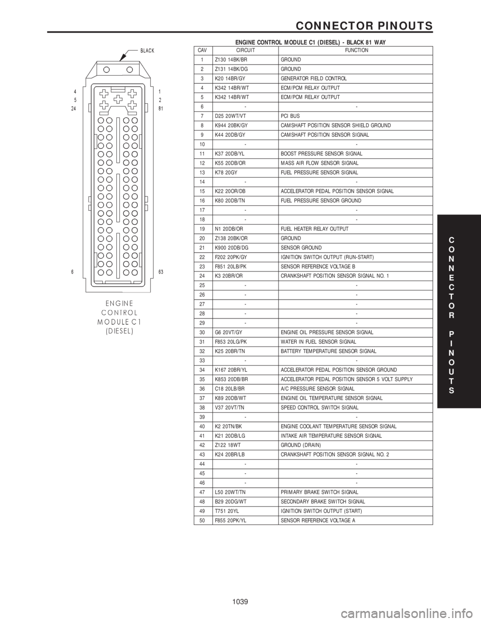
ENGINE CONTROL MODULE C1 (DIESEL) - BLACK 81 WAYCAV CIRCUIT FUNCTION
1 Z130 14BK/BR GROUND
2 Z131 14BK/DG GROUND
3 K20 14BR/GY GENERATOR FIELD CONTROL
4 K342 14BR/WT ECM/PCM RELAY OUTPUT
5 K342 14BR/WT ECM/PCM RELAY OUTPUT
6- -
7 D25 20WT/VT PCI BUS
8 K944 20BK/GY CAMSHAFT POSITION SENSOR SHIELD GROUND
9 K44 20DB/GY CAMSHAFT POSITION SENSOR SIGNAL
10 - -
11 K37 20DB/YL BOOST PRESSURE SENSOR SIGNAL
12 K55 20DB/OR MASS AIR FLOW SENSOR SIGNAL
13 K78 20GY FUEL PRESSURE SENSOR SIGNAL
14 - -
15 K22 20OR/DB ACCELERATOR PEDAL POSITION SENSOR SIGNAL
16 K80 20DB/TN FUEL PRESSURE SENSOR GROUND
17 - -
18 - -
19 N1 20DB/OR FUEL HEATER RELAY OUTPUT
20 Z138 20BK/OR GROUND
21 K900 20DB/DG SENSOR GROUND
22 F202 20PK/GY IGNITION SWITCH OUTPUT (RUN-START)
23 F851 20LB/PK SENSOR REFERENCE VOLTAGE B
24 K3 20BR/OR CRANKSHAFT POSITION SENSOR SIGNAL NO. 1
25 - -
26 - -
27 - -
28 - -
29 - -
30 G6 20VT/GY ENGINE OIL PRESSURE SENSOR SIGNAL
31 F853 20LG/PK WATER IN FUEL SENSOR SIGNAL
32 K25 20BR/TN BATTERY TEMPERATURE SENSOR SIGNAL
33 - -
34 K167 20BR/YL ACCELERATOR PEDAL POSITION SENSOR GROUND
35 K853 20DB/BR ACCELERATOR PEDAL POSITION SENSOR 5 VOLT SUPPLY
36 C18 20LB/BR A/C PRESSURE SENSOR SIGNAL
37 K89 20DB/WT ENGINE OIL TEMPERATURE SENSOR SIGNAL
38 V37 20VT/TN SPEED CONTROL SWITCH SIGNAL
39 - -
40 K2 20TN/BK ENGINE COOLANT TEMPERATURE SENSOR SIGNAL
41 K21 20DB/LG INTAKE AIR TEMPERATURE SENSOR SIGNAL
42 Z122 18WT GROUND (DRAIN)
43 K24 20BR/LB CRANKSHAFT POSITION SENSOR SIGNAL NO. 2
44 - -
45 - -
46 - -
47 L50 20WT/TN PRIMARY BRAKE SWITCH SIGNAL
48 B29 20DG/WT SECONDARY BRAKE SWITCH SIGNAL
49 T751 20YL IGNITION SWITCH OUTPUT (START)
50 F855 20PK/YL SENSOR REFERENCE VOLTAGE A
C
O
N
N
E
C
T
O
R
P
I
N
O
U
T
S
1039
CONNECTOR PINOUTS
Page 1069 of 4284

ENGINE CONTROL MODULE C1 (DIESEL) - BLACK 81 WAY - CONTINUEDCAV CIRCUIT FUNCTION
51 - -
52 K121 20DB BOOST PRESSURE SENSOR GROUND
53 - -
54 K957 20BK/OR MASS AIR FLOW SENSOR GROUND
55 N7 20DB/OR VEHICLE SPEED SENSOR SIGNAL
56 C918 20BK/LB A/C PRESSURE SENSOR GROUND
57 - -
58 K4 20BK/LB LOW IDLE POSITION SWITCH GROUND
59 - -
60 K9 20LB FUEL PRESSURE SENSOR 5 VOLT SUPPLY
61 K51 20BR/WT ECM/PCM RELAY CONTROL
62 - -
63 D21 20WT/BR SCI TRANSMIT
64 K151 20WT LOW IDLE POSITION SWITCH SENSE
65 - -
66 K936 20BR/YL ENGINE OIL PRESSURE SENSOR GROUND
67 - -
68 - -
69 C13 20LB/OR A/C COMPRESSOR CLUTCH RELAY CONTROL
70 N210 20DB/DG LOW SPEED RADIATOR FAN RELAY CONTROL
71 - -
72 N21 20DB/TN LIFT PUMP RELAY CONTROL
73 - -
74 T752 20DG/OR ENGINE STARTER MOTOR RELAY CONTROL
75 - -
76 - -
77 K152 20DB/WT GLOW PLUG RELAY CONTROL
78 N122 20DB/YL HIGH SPEED RADIATOR FAN DUAL RELAY CONTROL
79 - -
80 K87 20BR FUEL PRESSURE SOLENOID CONTROL
81 K87 20BR FUEL PRESSURE SOLENOID CONTROL
C
O
N
N
E
C
T
O
R
P
I
N
O
U
T
S
1040
CONNECTOR PINOUTS