key CHRYSLER VOYAGER 2001 Service Manual
[x] Cancel search | Manufacturer: CHRYSLER, Model Year: 2001, Model line: VOYAGER, Model: CHRYSLER VOYAGER 2001Pages: 4284, PDF Size: 83.53 MB
Page 3581 of 4284
(4) Align hood latch by placing latch over net
pierced tabs. If alignment is required, flatten or
grind tabs.
(5) Verify hood operation and alignment. Adjust as
necessary.
(6) Tighten attaching bolts to 13.5 N´m (10 ft. lbs.)
torque.
LATCH RELEASE CABLE
REMOVAL
(1) Remove hood latch.
(2) Disengage cable end from hood latch locking
mechanism.
(3) Slide cable case end sideways in keyhole slot of
hood latch while pinching barb on cable case closed.
(4) Remove cable from latch (Fig. 4).
(5) Remove hood release handle from instrument
panel.
(6) Disengage rubber grommet cable insulator
from hole in dash panel.
(7) Attach a suitable length of mechanic's wire to
latch end of cable to assist cable installation.
(8) Route cable back from latch through engine
compartment toward dash panel near power brake
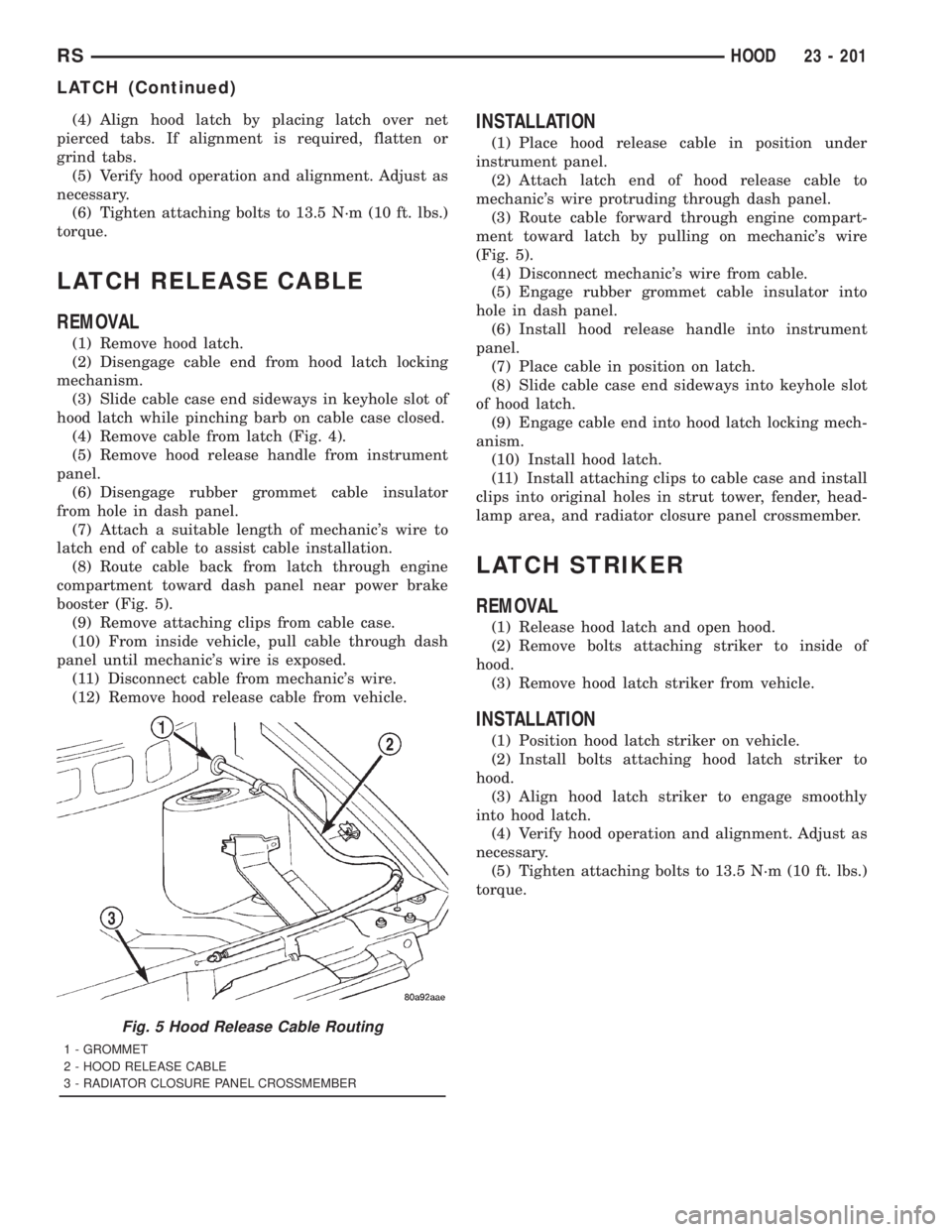
booster (Fig. 5).
(9) Remove attaching clips from cable case.
(10) From inside vehicle, pull cable through dash
panel until mechanic's wire is exposed.
(11) Disconnect cable from mechanic's wire.
(12) Remove hood release cable from vehicle.
INSTALLATION
(1) Place hood release cable in position under
instrument panel.
(2) Attach latch end of hood release cable to
mechanic's wire protruding through dash panel.
(3) Route cable forward through engine compart-
ment toward latch by pulling on mechanic's wire
(Fig. 5).
(4) Disconnect mechanic's wire from cable.
(5) Engage rubber grommet cable insulator into
hole in dash panel.
(6) Install hood release handle into instrument
panel.
(7) Place cable in position on latch.
(8) Slide cable case end sideways into keyhole slot
of hood latch.
(9) Engage cable end into hood latch locking mech-
anism.
(10) Install hood latch.
(11) Install attaching clips to cable case and install
clips into original holes in strut tower, fender, head-
lamp area, and radiator closure panel crossmember.
LATCH STRIKER
REMOVAL
(1) Release hood latch and open hood.
(2) Remove bolts attaching striker to inside of
hood.
(3) Remove hood latch striker from vehicle.
INSTALLATION
(1) Position hood latch striker on vehicle.
(2) Install bolts attaching hood latch striker to
hood.
(3) Align hood latch striker to engage smoothly
into hood latch.
(4) Verify hood operation and alignment. Adjust as
necessary.
(5) Tighten attaching bolts to 13.5 N´m (10 ft. lbs.)
torque.
Fig. 5 Hood Release Cable Routing
1 - GROMMET
2 - HOOD RELEASE CABLE
3 - RADIATOR CLOSURE PANEL CROSSMEMBER
RSHOOD23 - 201
LATCH (Continued)
Page 3634 of 4284
cloudy days and at night it will probably be slightly
warmer. Infrared Three-Zone Temperature Control
provides side-to-side and front-to-rear variation in
comfort temperature settings. The Infrared Three-
Zone Automatic Temperature Control fan provides a
continuously variable air flow rate to meet occupant
comfort requirements.
FRONT CONTROL PANEL
²AUTO HI/LO± This system features two sets of
automatic control logic that allow either a rapid cool-
down rate or a somewhat slower cool-down rate with
less fan noise. HI-AUTO controls the system to reach
its assigned temperature quickly with a higher fan
speed. LO-AUTO controls the system to reach its
assigned temperature somewhat slower with less fan
noise. Both modes will automatically engage auto
recirculation.
²DE-FROST± The front de-frost function is
active when the rear window defogger function is
active or when the defog/defrost mode is selected.
²RECIRC± The RECIRC button will close the
air inlet door. If the system is in auto recirc (indica-
tor being displayed automatically), pressing the man-
ual recirc button will disable the auto recirc function
until one of the auto keys are pressed or the ignition
is cycled. If Auto HI/LO is pressed while manual
recirc is active, manual recirc will be deactivated.
²REAR WINDOW DEFOGGER± Pushing the
button sends a PCI bus message to the Intelligent
Power Module which controls the Rear Window
Defogger and side view mirror (if equipped) circuitry.
The defogger function will be active for 10 minutes
and can be turned off by a switch press. The defogger
will function while the control is in the OFF mode.
²FAN/MODE± The Fan and Mode knobs have
17 manual selectable positions. Manually changing
either of the rotary knobs for mode or fan speed set-
tings makes control of that function alone manual for
as long as the ignition is on. If only one is changed
manually, the other remains under automatic control.
Pressing the HI-AUTO/LO-AUTO rocker switch
restores full automatic control.
²REAR CONTROL± When the Rear System
control knob is moved to the OFF position, there will
be a delay of approximately 1 second before the sys-
tem actually turns off. This delay is to prevent an
undesired blower dropout if the knob is moved
through OFF to the other selections.
²BLOWER DELAY TIMER± The word DELAY
is displayed at start-up to signify that the system is
waiting so that cold air will not be blowing. This tells
the operator that it is unnecessary to turn the sys-
tem off, raise the temperature setting or turn the fan
speed setting down to prevent cold air from blowing.
A countdown in minutes and seconds until the engineis warm enough to begin delivering heat to the pas-
sengers alternates with the DELAY message at 25
second intervals. This countdown is based on actual
measurement of the rate of engine coolant tempera-
ture change. During the delay time, Defrost mode is
selected and the fan operates at a low speed to keep
the windshield fog free.
REAR CONTROL PANEL
Primary control of the rear compartment unit is in
the instrument panel center stack. The rear unit con-
trol knob there allows the driver to turn the rear
unit off, allow control by the intermediate seat occu-
pants by switching to the REAR position, or provide
fully automatic control based on the temperature set-
ting shown on the front control display.
²REAR CONTROL± Selecting automatic control
of the rear unit at the instrument panel, illuminates
a Locked Padlock in the rear control panel display.
Selecting REAR activates the rear control panel and
the Padlock then appears unlocked.
²FAN KNOB± The rear fan control has Off and
AUTO positions and a range of manual speed set-
tings that override the AUTO setting.
²MODE KNOB± The mode control allows inter-
mediate seat occupants to manually override the
automatic mode and select any balance of air flow
between overhead and floor outlets from full over-
head to full floor.
²SET TEMP± The rear set temp control will
operate identical to the front controls. If the front
control rear set temp button is pressed simulta-
neously with the rear control head, then the front
control head press events shall have priority, i.e. if
the front user presses Rear Set Temp down and the
rear user presses Set Temp up, then the rear set
temp will decrease.
DIAGNOSIS AND TESTING - A/C COOL DOWN
TEST
The heater-A/C control module can perform an A/C
cool down test, which is a test performed during the
manufacturing process to confirm that the air condi-
tioning system is performing satisfactorily. This test
can also provide a quick confirmation of air condi-
tioning system performance to the service technician.
If the test is completed satisfactorily, no further ser-
vice is required. If the test is failed, proceed to the
A/C Performance Test to confirm the a/c system is
operating properly, or use a DRBIIItscan tool to
diagnose the A/C system control and distribution sys-
tems. Refer to the appropriate diagnostic informa-
tion.
24 - 4 HEATING & AIR CONDITIONINGRS
HEATING & AIR CONDITIONING (Continued)
Page 3647 of 4284

(2) Install and tighten the two screws that secure
the blower motor resistor to the evaporator housing.
Tighten the screws to 2 N´m (17 in. lbs.).
(3) Reconnect the blower motor pigtail wire con-
nector to the blower motor resistor connector recep-
tacle.
(4) Reconnect the instrument panel wire harness
connector for the blower motor resistor to the resistor
connector receptacle.
(5) Flex both sides of the glove box bin inward
near the top far enough for the rubber glove box stop
bumpers to clear the sides of the glove box opening,
then roll the glove box upward.
(6) Close and latch the glove box.
(7) Reconnect the battery negative cable.
COMPRESSOR CLUTCH
DESCRIPTION
The compressor clutch assembly consists of a sta-
tionary electromagnetic coil with a zener diode, a hub
bearing and pulley assembly, and a clutch plate (Fig.
12). The electromagnetic coil unit and the hub bear-
ing and pulley assembly are each retained on the
nose of the compressor front housing with snap rings.
The clutch plate is keyed or splined to the compres-
sor shaft, and secured with a bolt.
The compressor clutch plate and pulley unit, or the
clutch coil are available for separate service replace-
ment. The clutch coil zener diode is integral to the
clutch coil pigtail wire and connector and, if faulty ordamaged, the clutch electromagnetic coil unit must
be replaced.
OPERATION
The compressor clutch components provide the
means to engage and disengage the compressor from
the engine serpentine accessory drive belt. When the
clutch coil is energized, it magnetically draws the
clutch plate into contact with the clutch pulley and
drives the compressor shaft. When the coil is not
energized, the pulley freewheels on the clutch hub
bearing, which is part of the pulley.
A zener diode is connected in parallel with the
clutch electromagnetic coil. This diode controls the
dissipation of voltage induced into the coil windings
by the collapsing of the electromagnetic fields that
occurs when the compressor clutch is disengaged.
The zener diode dissipates this induced voltage by
regulating a current path to ground. This arrange-
ment serves to protect other circuits and components
from potentially damaging voltage spikes in the vehi-
cle electrical system that might occur if the voltage
induced in the clutch coil windings could not be dis-
sipated.
The compressor clutch engagement is controlled by
several components: the heater-A/C controls in the
passenger compartment, the A/C pressure transducer
on the liquid line, the evaporator temperature sensor
on the expansion valve, the Powertrain Control Mod-
ule (PCM) in the engine compartment, and the com-
pressor clutch relay in the Intelligent Power Module
(IPM). The PCM may delay compressor clutch
engagement for up to thirty seconds. (Refer to 8 -
Fig. 11 Blower Motor Resistor
1 - BLOWER MOTOR RESISTOR
2 - INSTRUMENT PANEL WIRE HARNESS
3 - SCREW (2)
4 - GLOVE BOX OPENING LOWER REINFORCEMENT
5 - BLOWER MOTOR PIGTAIL WIRE
6 - EVAPORATOR HOUSING
Fig. 12 Compressor Clutch - Typical
1 - CLUTCH PLATE
2 - SHAFT KEY (SOME MODELS)
3 - PULLEY AND BEARING
4 - CLUTCH COIL
5 - CLUTCH SHIMS
6 - SNAP RING
7 - SNAP RING
RSCONTROLS - FRONT24-17
BLOWER MOTOR RESISTOR (Continued)
Page 3748 of 4284
NOTE:Do not activate the Dosing Pump Prime more
than one time. This will put excess fuel in the DCHA
Heater Module an cause smoke to emit from the
DCHA exhaust pipe when heater activation occurs.
NOTE: A clicking noise heard coming from the Dos-
ing Pump indicates that the pump is operational.
(7)
With the DRBIIItin Cabin Heater, select Sys-
tem Tests and Dosing Pump Prime. Allow the Dosing
Pump to run for the full 45 second cycle time. When
the 45 second cycle is complete, press Page Back on
the DRBIIItkey pad to exit the Dosing Pump Prime.
The Dosing Pump priming procedure is now complete.
HEATER UNIT
REMOVAL
WARNING: ALLOW THE DCHA TO COOL BEFORE
PERFORMING A COMPONENT INSPECTION/REPAIR
OR REPLACEMENT. FAILURE TO FOLLOW THESE
INSTRUCTIONS MAY RESULT IN PERSONAL
INJURY.
WARNING: ALLOW THE EXHAUST SYSTEM TO
COOL BEFORE PERFORMING A COMPONENT
INSPECTION/REPAIR OR REPLACEMENT. FAILURE
TO FOLLOW THESE INSTRUCTION MAY RESULT IN
PERSONAL INJURY.
(1) Elevate the vehicle on a hoist/lift taking note of
heater exhaust tube flexible section.
(2) Drain cooling system(Refer to 7 - COOLING -
STANDARD PROCEDURE).
(3) Carefully open one hose to the underbody tube
assembly and drain the remaining coolant. A salvage
hose is a good idea to control the residual coolant, as
flow will occur from both the heater and the hose and
tube assemblies.
(4) Remove the second hose from the underbody
hose and tube assembly.
(5) Loosen the hose and tube assembly from the
toe-board cross member at two locations.
(6) Disconnect the electrical connector from the
body harness near the toe board cross member and
rail.
(7) Remove the wiring harness from the toe board
cross member(Refer to 24 - HEATING & AIR CON-
DITIONING/CABIN HEATER/HEATER UNIT -
REMOVAL).
(8) Open the fuel fill cap. Disconnect the rubber
fuel hose between the body tube assembly and the
fuel pump nipple at the body tube joint. A minimal
amount of fuel may flow from the open port.NOTE: Utilize an approved fuel storage container to
catch any residual fuel.
(9) Loosen the two M8 fasteners at the rail. Take
care to notice that the exhaust tube bracket tab is on
top of the heater bracket.
(10) Remove the heater exhaust tube flex section
from the exhaust tube by loosening the M6 bolt of
the clamp assembly. Remove the hose from the
exhaust tube. Removal of the rail tube assembly may
aid in this service operation.(Refer to 24 - HEATING
& AIR CONDITIONING/CABIN HEATER/EXHAUST
TUBE - REMOVAL).
(11) Remove seat hex nut at the heater mounting
flange to cross member.
(12) Loosen the remaining M6 and M8 fasteners
which mount the exhaust tube assembly to the vehi-
cle.
(a) Install a suitable cabin heater support device
under the cabin heater and secure the cabin heater
to the device.
(13) Loosen the remaining three M6 fasteners to
the cross members.
(14) Remove the loosened fasteners that support
the heater while supporting the weight of the heater.
(15) Swing the unit mounting bracket from
between the exhaust bracket and rail mounting loca-
tion. Drain any residual coolant from the heater unit.
(16) Lower the cabin heater and remove from the
supporting device and place on a suitable work area.
INSTALLATION
(1) Install the unit mounting bracket between the
exhaust bracket and the rail mounting location.
(2) Install the fasteners that support the heater
while supporting the weight of the heater.
(3) Install the three M6 fasteners to the cross
members. Tighten the M6 fasteners to 7 Nm (5 ft.
lbs.).
(4) Tighten the remaining M6 fasteners to 7 Nm (5
ft. lbs.) and the M8 fasteners to 23 Nm (17 ft. lbs.)
which mount the exhaust tube assembly to the vehi-
cle.
(5) Install the seat hex nut at the heater mounting
flange to the cross members. Tighten to 60 Nm (44 ft.
lbs.)
(6) Install the heater exhaust tube flex section to
the exhaust tube by tightening the M6 bolt of the
clamp assembly. Install the hose to the exhaust tube.
(7) Tighten the two M8 fasteners at the rail to 23
Nm (17 ft. lbs.). Taking care so that the exhaust tube
bracket tab is on the top of the heater bracket.
(8) Install the wiring harness(Refer to 24 - HEAT-
ING & AIR CONDITIONING/CABIN HEATER/
HEATER UNIT - INSTALLATION).
24a - 10 HEATING & AIR CONDITIONINGRG
FUEL LINE (Continued)
Page 3753 of 4284

²Vehicle Speed Sensor
²Engine Coolant Temperature Sensor
²Throttle Position Sensor
²Engine Controller Self Test Faults
²Cam or Crank Sensor
²Injector and Coil
²Idle Air Control Motor
²EVAP Electrical
²EGR Solenoid Electrical
²Intake Air Temperature
²5 Volt Feed
ConflictÐThe Task Manager does not run the
Oxygen Sensor Monitor if any of the following condi-
tions are present:
²A/C ON (A/C clutch cycling temporarily sus-
pends monitor)
²Purge flow in progress
²Ethanel content learn is takeng place and the
ethenal used once flag is set
SuspendÐThe Task Manager suspends maturing
a fault for the Oxygen Sensor Monitor if an of the fol-
lowing are present:
²Oxygen Sensor Heater Monitor, Priority 1
²Misfire Monitor, Priority 2
OXYGEN SENSOR HEATER MONITOR
DESCRIPTIONÐIf there is an oxygen sensor
(O2S) DTC as well as a O2S heater DTC, the O2S
fault MUST be repaired first. After the O2S fault is
repaired, verify that the heater circuit is operating
correctly.
The voltage readings taken from the O2S are very
temperature sensitive. The readings are not accurate
below 300ÉC. Heating of the O2S is done to allow the
engine controller to shift to closed loop control as
soon as possible. The heating element used to heat
the O2S must be tested to ensure that it is heating
the sensor properly.
The heater element itself is not tested. The sensor
output is used to test the heater by isolating the
effect of the heater element on the O2S output volt-
age from the other effects. The resistance is normally
between 100 ohms and 4.5 megaohms. When oxygen
sensor temperature increases, the resistance in the
internal circuit decreases. The PCM sends a 5 volts
biased signal through the oxygen sensors to ground
this monitoring circuit. As the temperature increases,
resistance decreases and the PCM detects a lower
voltage at the reference signal. Inversely, as the tem-
perature decreases, the resistance increases and the
PCM detects a higher voltage at the reference signal.
The O2S circuit is monitored for a drop in voltage.
OPERATIONÐThe Oxygen Sensor Heater Moni-
tor begins after the ignition has been turned OFF
and the O2 sensors have cooled. The PCM sends a 5
volt bias to the oxygen sensor every 1.6 seconds. ThePCM keeps it biased for 35 ms each time. As the sen-
sor cools down, the resistance increases and the PCM
reads the increase in voltage. Once voltage has
increased to a predetermined amount, higher than
when the test started, the oxygen sensor is cool
enough to test heater operation.
When the oxygen sensor is cool enough, the PCM
energizes the ASD relay. Voltage to the O2 sensor
begins to increase the temperature. As the sensor
temperature increases, the internal resistance
decreases. The PCM continues biasing the 5 volt sig-
nal to the sensor. Each time the signal is biased, the
PCM reads a voltage decrease. When the PCM
detects a voltage decrease of a predetermined value
for several biased pulses, the test passes.
The heater elements are tested each time the
engine is turned OFF if all the enabling conditions
are met. If the monitor fails, the PCM stores a
maturing fault and a Freeze Frame is entered. If two
consecutive tests fail, a DTC is stored. Because the
ignition is OFF, the MIL is illuminated at the begin-
ning of the next key cycle.
Enabling ConditionsÐThe following conditions
must be met for the PCM to run the oxygen sensor
heater test:
²Engine run time of at least 5.1 minutes
²Key OFF power down
²Battery voltage of at least 10 volts
²Sufficient Oxygen Sensor cool down
Pending ConditionsÐThere are not conditions or
situations that prompt conflict or suspension of test-
ing. The oxygen sensor heater test is not run pending
resolution of MIL illumination due to oxygen sensor
failure.
SuspendÐThere are no conditions which exist for
suspending the Heater Monitor.
CATALYST MONITOR
To comply with clean air regulations, vehicles are
equipped with catalytic converters. These converters
reduce the emission of hydrocarbons, oxides of nitro-
gen and carbon monoxide.
Normal vehicle miles or engine misfire can cause a
catalyst to decay. A meltdown of the ceramic core can
cause a reduction of the exhaust passage. This can
increase vehicle emissions and deteriorate engine
performance, driveability and fuel economy.
The catalyst monitor uses dual oxygen sensors
(O2S's) to monitor the efficiency of the converter. The
dual O2S strategy is based on the fact that as a cat-
alyst deteriorates, its oxygen storage capacity and its
efficiency are both reduced. By monitoring the oxy-
gen storage capacity of a catalyst, its efficiency can
be indirectly calculated. The upstream O2S is used to
detect the amount of oxygen in the exhaust gas
before the gas enters the catalytic converter. The
RSEMISSIONS CONTROL25-3
EMISSIONS CONTROL (Continued)
Page 3774 of 4284
The Task Manager Screen shows both a Requested
MIL state and an Actual MIL state. When the MIL is
illuminated upon completion of a test for a third trip,
the Requested MIL state changes to OFF. However,
the MIL remains illuminated until the next key
cycle. (On some vehicles, the MIL will actually turn
OFF during the third key cycle) During the key cycle
for the third good trip, the Requested MIL state is
OFF, while the Actual MILL state is ON. After the
next key cycle, the MIL is not illuminated and both
MIL states read OFF.
Diagnostic Trouble Codes (DTCs)
With OBD II, different DTC faults have different
priorities according to regulations. As a result, the
priorities determine MIL illumination and DTC era-
sure. DTCs are entered according to individual prior-
ity. DTCs with a higher priority overwrite lower
priority DTCs.
Priorities
²Priority 0 ÐNon-emissions related trouble codes
²Priority 1 Ð One trip failure of a two trip fault
for non-fuel system and non-misfire.
²Priority 2 Ð One trip failure of a two trip fault
for fuel system (rich/lean) or misfire.
²Priority3ÐTwotrip failure for a non-fuel sys-
tem and non-misfire or matured one trip comprehen-
sive component fault.
²Priority4ÐTwotrip failure or matured fault
for fuel system (rich/lean) and misfire or one trip cat-
alyst damaging misfire.
Non-emissions related failures have no priority.
One trip failures of two trip faults have low priority.
Two trip failures or matured faults have higher pri-
ority. One and two trip failures of fuel system and
misfire monitor take precedence over non-fuel system
and non-misfire failures.
DTC Self Erasure
With one trip components or systems, the MIL is
illuminated upon test failure and DTCs are stored.
Two trip monitors are components requiring failure
in two consecutive trips for MIL illumination. Upon
failure of the first test, the Task Manager enters a
maturing code. If the component fails the test for a
second time the code matures and a DTC is set.
After three good trips the MIL is extinguished and
the Task Manager automatically switches the trip
counter to a warm-up cycle counter. DTCs are auto-
matically erased following 40 warm-up cycles if the
component does not fail again.
For misfire and fuel system monitors, the compo-
nent must pass the test under a Similar Conditions
Window in order to record a good trip. A Similar Con-
ditions Window is when engine RPM is within6375RPM and load is within610% of when the fault
occurred.
NOTE: It is important to understand that a compo-
nent does not have to fail under a similar window of
operation to mature. It must pass the test under a
Similar Conditions Window when it failed to record
a Good Trip for DTC erasure for misfire and fuel
system monitors.
DTCs can be erased anytime with a DRBIIIt.
Erasing the DTC with the DRBIIIterases all OBD II
information. The DRBIIItautomatically displays a
warning that erasing the DTC will also erase all
OBD II monitor data. This includes all counter infor-
mation for warm-up cycles, trips and Freeze Frame.
Trip Indicator
TheTripis essential for running monitors and
extinguishing the MIL. In OBD II terms, a trip is a
set of vehicle operating conditions that must be met
for a specific monitor to run. All trips begin with a
key cycle.
Good Trip
The Good Trip counters are as follows:
²Global Good Trip
²Fuel System Good Trip
²Misfire Good Trip
²Alternate Good Trip (appears as a Global Good
Trip on DRBIIIt)
²Comprehensive Components
²Major Monitor
²Warm-Up Cycles
Global Good Trip
To increment a Global Good Trip, the Oxygen sen-
sor and Catalyst efficiency monitors must have run
and passed.
Fuel System Good Trip
To count a good trip (three required) and turn off
the MIL, the following conditions must occur:
²Engine in closed loop
²Operating in Similar Conditions Window
²Short Term multiplied by Long Term less than
threshold
²Less than threshold for a predetermined time
If all of the previous criteria are met, the PCM will
count a good trip (three required) and turn off the
MIL.
Misfire Good Trip
If the following conditions are met the PCM will
count one good trip (three required) in order to turn
off the MIL:
²Operating in Similar Condition Window
²1000 engine revolutions with no misfire
Alternate Good Trip
Alternate Good Trips are used in place of Global
Good Trips for Comprehensive Components and
25 - 24 ON-BOARD DIAGNOSTICSRS
TASK MANAGER (Continued)
Page 3777 of 4284

EMISSIONS CONTROL 2.5L TURBO DIESEL
TABLE OF CONTENTS
page page
EMISSIONS CONTROL 2.5L TURBO DIESEL
DESCRIPTION............................1
SPECIFICATIONS.........................2EXHAUST GAS RECIRCULATION.............3
ON-BOARD DIAGNOSTICS..................6
EMISSIONS CONTROL 2.5L
TURBO DIESEL
DESCRIPTION
The 2.5L diesel Engine Control Module (ECM) con-
trols many different circuits in the fuel injection
pump and engine systems. If the ECM senses a prob-
lem with a monitored circuit that indicates an actual
problem, a Diagnostic Trouble Code (DTC) will be
stored in the ECM's memory, and eventually may
illuminate the MIL (Malfunction Indicator Lamp)
constantly while the key is on. If the problem is
repaired, or is intermittent, the ECM will erase the
DTC after 40 warm-up cycles without the the fault
detected. A warm-up cycle consists of starting the
vehicle when the engine is cold, then the engine is
warmed up to a certain temperature, and finally, the
engine temperature falls to a normal operating tem-
perature, then the key is turned off.
Certain criteria must be met for a DTC to be
entered into ECM memory. The criteria may be a
specific range of engine rpm, engine or fuel tempera-
ture and/or input voltage to the ECM. A DTC indi-
cates that the ECM has identified an abnormal
signal in a circuit or the system.
There are several operating conditions that the
ECM does not monitor and set a DTC for. Refer to
the following Monitored Circuits and Non±Monitored
Circuits in this section.
ECM MONITORED SYSTEMS
The ECM can detect certain problems in the elec-
trical system.
Open or Shorted Circuit± The ECM will not
distinguish between an open or a short to ground,
however the ECM can determine if there is excessive
current on a circuit, such as a short to voltage or a
decrease in component resistance.
Output Device Current Flow± The ECM senses
whether the output devices are electrically connected.
If there is a problem with the circuit, the ECM
senses whether the circuit is open, shorted to ground
(±), or shorted to (+) voltage.Fuel Pressure:Fuel pressure is controlled by the
fuel injection pump and fuel pressure solenoid. The
ECM uses a fuel pressure sensor to determine if a
fuel pressure problem exists.
Fuel Injector Malfunctions:The ECM can deter-
mine if a fuel injector has an electrical problem. The
fuel injectors on the diesel engine arecontrolledby
the ECM.
ECM NON±MONITORED SYSTEMS
The ECM does not monitor the following circuits,
systems or conditions that could have malfunctions
that result in driveability problems. A DTC will not
be displayed for these conditions.
Cylinder Compression:The ECM cannot detect
uneven, low, or high engine cylinder compression.
Exhaust System:The ECM cannot detect a
plugged, restricted or leaking exhaust system.
Vacuum Assist:Leaks or restrictions in the vac-
uum circuits of the Exhaust Gas Recirculation Sys-
tem (EGR) are not monitored by the ECM.
ECM System Ground:The ECM cannot deter-
mine a poor system ground. However, a DTC may be
generated as a result of this condition.
ECM/PCM Connector Engagement:The ECM
cannot determine spread or damaged connector pins.
However, a DTC may be generated as a result of this
condition.
HIGH AND LOW LIMITS
The ECM compares input signals from each input
device. It has high and low limits that are pro-
grammed into it for that device. If the inputs are not
within specifications and other DTC criteria are met,
a DTC will be stored in memory. Other DTC criteria
might include engine rpm limits or input voltages
from other sensors or switches. The other inputs
might have to be sensed by the ECM when it senses
a high or low input voltage from the control system
device in question.
RGEMISSIONS CONTROL 2.5L TURBO DIESEL25a-1
Page 3785 of 4284
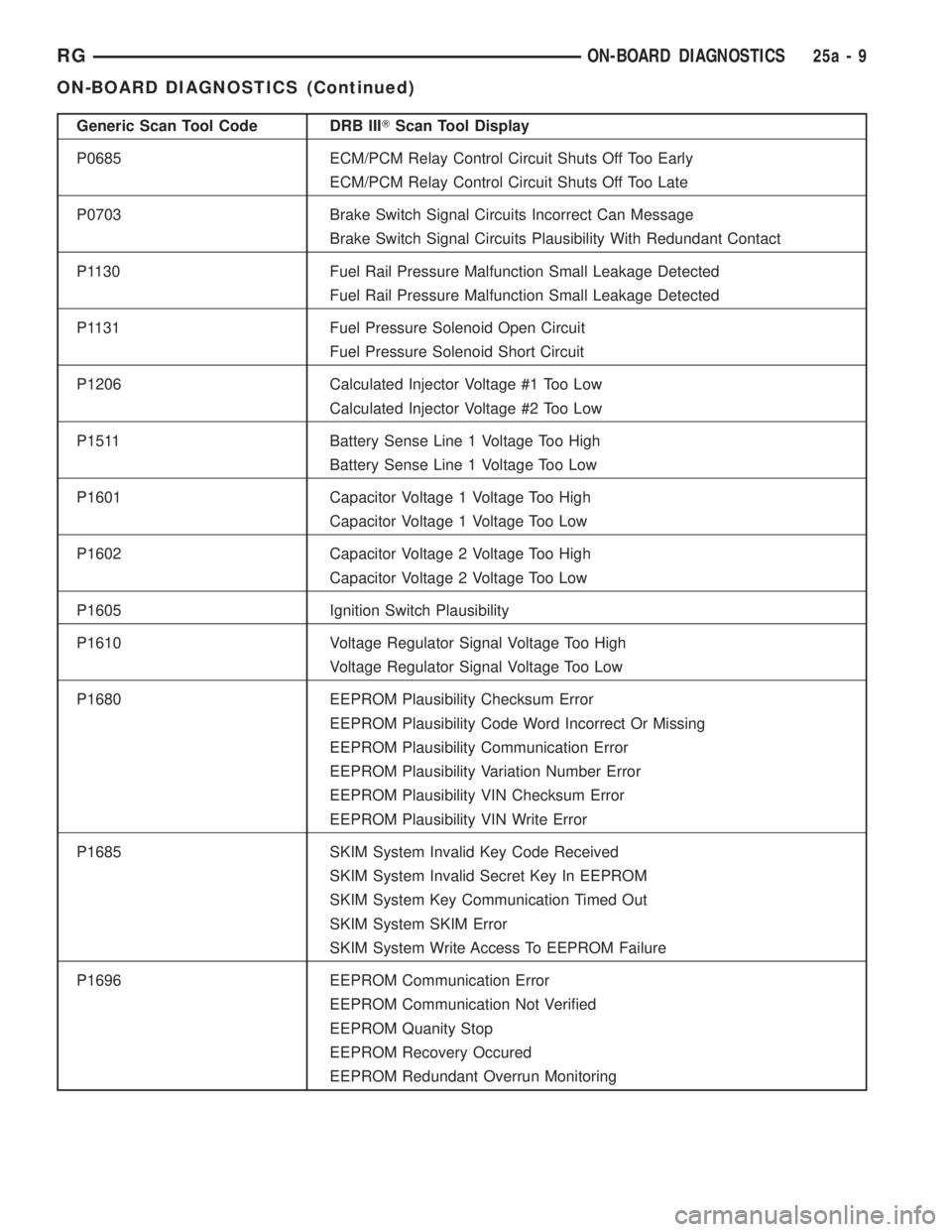
Generic Scan Tool Code DRB IIITScan Tool Display
P0685 ECM/PCM Relay Control Circuit Shuts Off Too Early
ECM/PCM Relay Control Circuit Shuts Off Too Late
P0703 Brake Switch Signal Circuits Incorrect Can Message
Brake Switch Signal Circuits Plausibility With Redundant Contact
P1130 Fuel Rail Pressure Malfunction Small Leakage Detected
Fuel Rail Pressure Malfunction Small Leakage Detected
P1131 Fuel Pressure Solenoid Open Circuit
Fuel Pressure Solenoid Short Circuit
P1206 Calculated Injector Voltage #1 Too Low
Calculated Injector Voltage #2 Too Low
P1511 Battery Sense Line 1 Voltage Too High
Battery Sense Line 1 Voltage Too Low
P1601 Capacitor Voltage 1 Voltage Too High
Capacitor Voltage 1 Voltage Too Low
P1602 Capacitor Voltage 2 Voltage Too High
Capacitor Voltage 2 Voltage Too Low
P1605 Ignition Switch Plausibility
P1610 Voltage Regulator Signal Voltage Too High
Voltage Regulator Signal Voltage Too Low
P1680 EEPROM Plausibility Checksum Error
EEPROM Plausibility Code Word Incorrect Or Missing
EEPROM Plausibility Communication Error
EEPROM Plausibility Variation Number Error
EEPROM Plausibility VIN Checksum Error
EEPROM Plausibility VIN Write Error
P1685 SKIM System Invalid Key Code Received
SKIM System Invalid Secret Key In EEPROM
SKIM System Key Communication Timed Out
SKIM System SKIM Error
SKIM System Write Access To EEPROM Failure
P1696 EEPROM Communication Error
EEPROM Communication Not Verified
EEPROM Quanity Stop
EEPROM Recovery Occured
EEPROM Redundant Overrun Monitoring
RGON-BOARD DIAGNOSTICS25a-9
ON-BOARD DIAGNOSTICS (Continued)
Page 3789 of 4284
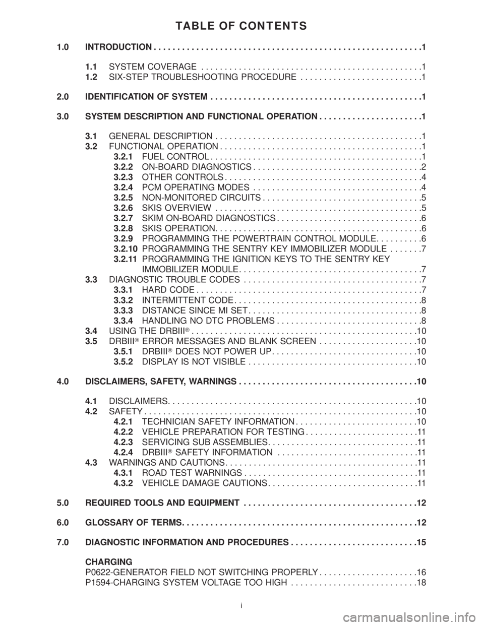
TABLE OF CONTENTS
1.0 INTRODUCTION.........................................................1
1.1SYSTEM COVERAGE...............................................1
1.2SIX-STEP TROUBLESHOOTING PROCEDURE..........................1
2.0 IDENTIFICATION OF SYSTEM.............................................1
3.0 SYSTEM DESCRIPTION AND FUNCTIONAL OPERATION......................1
3.1GENERAL DESCRIPTION............................................1
3.2FUNCTIONAL OPERATION...........................................1
3.2.1FUEL CONTROL.............................................1
3.2.2ON-BOARD DIAGNOSTICS....................................2
3.2.3OTHER CONTROLS..........................................4
3.2.4PCM OPERATING MODES....................................4
3.2.5NON-MONITORED CIRCUITS..................................5
3.2.6SKIS OVERVIEW............................................5
3.2.7SKIM ON-BOARD DIAGNOSTICS...............................6
3.2.8SKIS OPERATION............................................6
3.2.9PROGRAMMING THE POWERTRAIN CONTROL MODULE..........6
3.2.10PROGRAMMING THE SENTRY KEY IMMOBILIZER MODULE.......7
3.2.11PROGRAMMING THE IGNITION KEYS TO THE SENTRY KEY
IMMOBILIZER MODULE.......................................7
3.3DIAGNOSTIC TROUBLE CODES......................................7
3.3.1HARD CODE................................................7
3.3.2INTERMITTENT CODE........................................8
3.3.3DISTANCE SINCE MI SET.....................................8
3.3.4HANDLING NO DTC PROBLEMS...............................8
3.4USING THE DRBIIIT................................................10
3.5DRBIIITERROR MESSAGES AND BLANK SCREEN.....................10
3.5.1DRBIIITDOES NOT POWER UP...............................10
3.5.2DISPLAY IS NOT VISIBLE....................................10
4.0 DISCLAIMERS, SAFETY, WARNINGS......................................10
4.1DISCLAIMERS.....................................................10
4.2SAFETY..........................................................10
4.2.1TECHNICIAN SAFETY INFORMATION..........................10
4.2.2VEHICLE PREPARATION FOR TESTING........................11
4.2.3SERVICING SUB ASSEMBLIES................................11
4.2.4DRBIIITSAFETY INFORMATION..............................11
4.3WARNINGS AND CAUTIONS.........................................11
4.3.1ROAD TEST WARNINGS.....................................11
4.3.2VEHICLE DAMAGE CAUTIONS................................11
5.0 REQUIRED TOOLS AND EQUIPMENT.....................................12
6.0 GLOSSARY OF TERMS..................................................12
7.0 DIAGNOSTIC INFORMATION AND PROCEDURES...........................15
CHARGING
P0622-GENERATOR FIELD NOT SWITCHING PROPERLY.....................16
P1594-CHARGING SYSTEM VOLTAGE TOO HIGH...........................18
i
Page 3790 of 4284
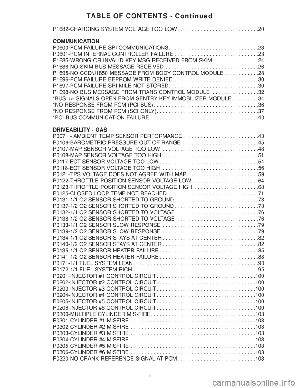
TABLE OF CONTENTS - Continued
P1682-CHARGING SYSTEM VOLTAGE TOO LOW............................20
COMMUNICATION
P0600-PCM FAILURE SPI COMMUNICATIONS...............................23
P0601-PCM INTERNAL CONTROLLER FAILURE.............................23
P1685-WRONG OR INVALID KEY MSG RECEIVED FROM SKIM................24
P1686-NO SKIM BUS MESSAGE RECEIVED................................26
P1695-NO CCD/J1850 MESSAGE FROM BODY CONTROL MODULE............28
P1696-PCM FAILURE EEPROM WRITE DENIED.............................30
P1697-PCM FAILURE SRI MILE NOT STORED...............................30
P1698-NO BUS MESSAGE FROM TRANS CONTROL MODULE................32
*BUS +/- SIGNALS OPEN FROM SENTRY KEY IMMOBILIZER MODULE.........34
*NO RESPONSE FROM PCM (PCI BUS)....................................36
*NO RESPONSE FROM PCM (SCI ONLY)...................................37
*PCI BUS COMMUNICATION FAILURE.....................................40
DRIVEABILITY - GAS
P0071 - AMBIENT TEMP SENSOR PERFORMANCE..........................43
P0106-BAROMETRIC PRESSURE OUT OF RANGE..........................45
P0107-MAP SENSOR VOLTAGE TOO LOW.................................48
P0108-MAP SENSOR VOLTAGE TOO HIGH.................................51
P0117-ECT SENSOR VOLTAGE TOO LOW..................................54
P0118-ECT SENSOR VOLTAGE TOO HIGH.................................56
P0121-TPS VOLTAGE DOES NOT AGREE WITH MAP........................59
P0122-THROTTLE POSITION SENSOR VOLTAGE LOW.......................64
P0123-THROTTLE POSITION SENSOR VOLTAGE HIGH......................68
P0125-CLOSED LOOP TEMP NOT REACHED...............................71
P0131-1/1 O2 SENSOR SHORTED TO GROUND.............................73
P0137-1/2 O2 SENSOR SHORTED TO GROUND.............................73
P0132-1/1 O2 SENSOR SHORTED TO VOLTAGE............................76
P0138-1/2 O2 SENSOR SHORTED TO VOLTAGE............................76
P0133-1/1 O2 SENSOR SLOW RESPONSE.................................79
P0139-1/2 O2 SENSOR SLOW RESPONSE.................................79
P0134-1/1 O2 SENSOR STAYS AT CENTER.................................82
P0140-1/2 O2 SENSOR STAYS AT CENTER.................................82
P0135-1/1 O2 SENSOR HEATER FAILURE..................................85
P0141-1/2 O2 SENSOR HEATER FAILURE..................................88
P0171-1/1 FUEL SYSTEM LEAN...........................................90
P0172-1/1 FUEL SYSTEM RICH...........................................95
P0201-INJECTOR #1 CONTROL CIRCUIT..................................100
P0202-INJECTOR #2 CONTROL CIRCUIT..................................100
P0203-INJECTOR #3 CONTROL CIRCUIT..................................100
P0204-INJECTOR #4 CONTROL CIRCUIT..................................100
P0205-INJECTOR #5 CONTROL CIRCUIT..................................100
P0206-INJECTOR #6 CONTROL CIRCUIT..................................100
P0300-MULTIPLE CYLINDER MIS-FIRE....................................103
P0301-CYLINDER #1 MISFIRE...........................................103
P0302-CYLINDER #2 MISFIRE...........................................103
P0303-CYLINDER #3 MISFIRE...........................................103
P0304-CYLINDER #4 MISFIRE...........................................103
P0305-CYLINDER #5 MISFIRE...........................................103
P0306-CYLINDER #6 MISFIRE...........................................103
P0320-NO CRANK REFERENCE SIGNAL AT PCM...........................108
ii