fuse CHRYSLER VOYAGER 2001 Service Manual
[x] Cancel search | Manufacturer: CHRYSLER, Model Year: 2001, Model line: VOYAGER, Model: CHRYSLER VOYAGER 2001Pages: 4284, PDF Size: 83.53 MB
Page 1414 of 4284
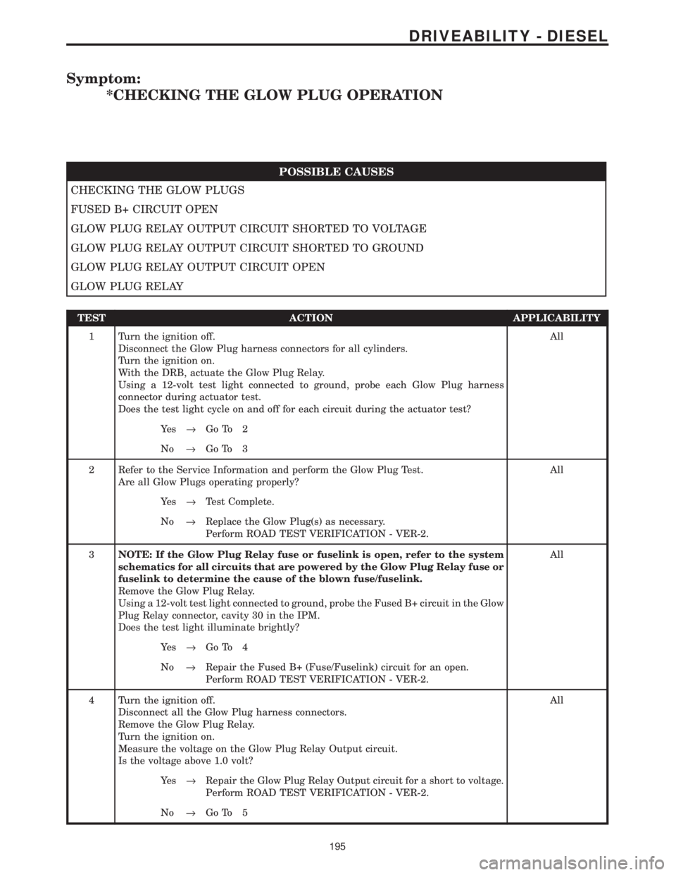
Symptom:
*CHECKING THE GLOW PLUG OPERATION
POSSIBLE CAUSES
CHECKING THE GLOW PLUGS
FUSED B+ CIRCUIT OPEN
GLOW PLUG RELAY OUTPUT CIRCUIT SHORTED TO VOLTAGE
GLOW PLUG RELAY OUTPUT CIRCUIT SHORTED TO GROUND
GLOW PLUG RELAY OUTPUT CIRCUIT OPEN
GLOW PLUG RELAY
TEST ACTION APPLICABILITY
1 Turn the ignition off.
Disconnect the Glow Plug harness connectors for all cylinders.
Turn the ignition on.
With the DRB, actuate the Glow Plug Relay.
Using a 12-volt test light connected to ground, probe each Glow Plug harness
connector during actuator test.
Does the test light cycle on and off for each circuit during the actuator test?All
Ye s®Go To 2
No®Go To 3
2 Refer to the Service Information and perform the Glow Plug Test.
Are all Glow Plugs operating properly?All
Ye s®Test Complete.
No®Replace the Glow Plug(s) as necessary.
Perform ROAD TEST VERIFICATION - VER-2.
3NOTE: If the Glow Plug Relay fuse or fuselink is open, refer to the system
schematics for all circuits that are powered by the Glow Plug Relay fuse or
fuselink to determine the cause of the blown fuse/fuselink.
Remove the Glow Plug Relay.
Using a 12-volt test light connected to ground, probe the Fused B+ circuit in the Glow
Plug Relay connector, cavity 30 in the IPM.
Does the test light illuminate brightly?All
Ye s®Go To 4
No®Repair the Fused B+ (Fuse/Fuselink) circuit for an open.
Perform ROAD TEST VERIFICATION - VER-2.
4 Turn the ignition off.
Disconnect all the Glow Plug harness connectors.
Remove the Glow Plug Relay.
Turn the ignition on.
Measure the voltage on the Glow Plug Relay Output circuit.
Is the voltage above 1.0 volt?All
Ye s®Repair the Glow Plug Relay Output circuit for a short to voltage.
Perform ROAD TEST VERIFICATION - VER-2.
No®Go To 5
195
DRIVEABILITY - DIESEL
Page 1415 of 4284
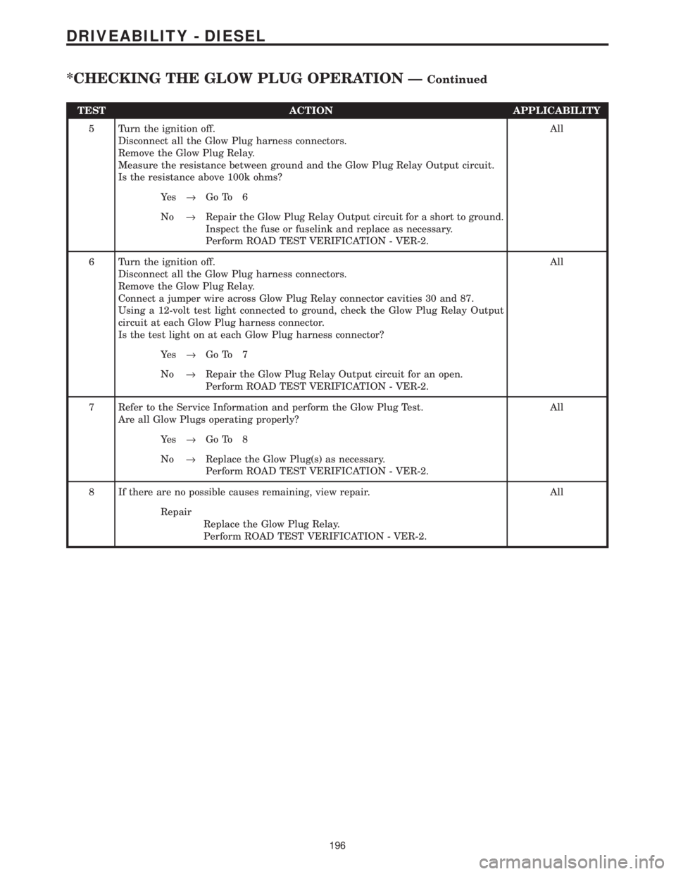
TEST ACTION APPLICABILITY
5 Turn the ignition off.
Disconnect all the Glow Plug harness connectors.
Remove the Glow Plug Relay.
Measure the resistance between ground and the Glow Plug Relay Output circuit.
Is the resistance above 100k ohms?All
Ye s®Go To 6
No®Repair the Glow Plug Relay Output circuit for a short to ground.
Inspect the fuse or fuselink and replace as necessary.
Perform ROAD TEST VERIFICATION - VER-2.
6 Turn the ignition off.
Disconnect all the Glow Plug harness connectors.
Remove the Glow Plug Relay.
Connect a jumper wire across Glow Plug Relay connector cavities 30 and 87.
Using a 12-volt test light connected to ground, check the Glow Plug Relay Output
circuit at each Glow Plug harness connector.
Is the test light on at each Glow Plug harness connector?All
Ye s®Go To 7
No®Repair the Glow Plug Relay Output circuit for an open.
Perform ROAD TEST VERIFICATION - VER-2.
7 Refer to the Service Information and perform the Glow Plug Test.
Are all Glow Plugs operating properly?All
Ye s®Go To 8
No®Replace the Glow Plug(s) as necessary.
Perform ROAD TEST VERIFICATION - VER-2.
8 If there are no possible causes remaining, view repair. All
Repair
Replace the Glow Plug Relay.
Perform ROAD TEST VERIFICATION - VER-2.
196
DRIVEABILITY - DIESEL
*CHECKING THE GLOW PLUG OPERATION ÐContinued
Page 1416 of 4284
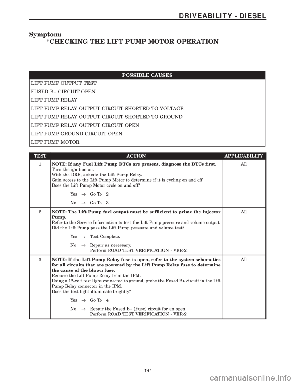
Symptom:
*CHECKING THE LIFT PUMP MOTOR OPERATION
POSSIBLE CAUSES
LIFT PUMP OUTPUT TEST
FUSED B+ CIRCUIT OPEN
LIFT PUMP RELAY
LIFT PUMP RELAY OUTPUT CIRCUIT SHORTED TO VOLTAGE
LIFT PUMP RELAY OUTPUT CIRCUIT SHORTED TO GROUND
LIFT PUMP RELAY OUTPUT CIRCUIT OPEN
LIFT PUMP GROUND CIRCUIT OPEN
LIFT PUMP MOTOR
TEST ACTION APPLICABILITY
1NOTE: If any Fuel Lift Pump DTCs are present, diagnose the DTCs first.
Turn the ignition on.
With the DRB, actuate the Lift Pump Relay.
Gain access to the Lift Pump Motor to determine if it is cycling on and off.
Does the Lift Pump Motor cycle on and off?All
Ye s®Go To 2
No®Go To 3
2NOTE: The Lift Pump fuel output must be sufficient to prime the Injector
Pump.
Refer to the Service Information to test the Lift Pump pressure and volume output.
Did the Lift Pump pass the Lift Pump pressure and volume test?All
Ye s®Test Complete.
No®Repair as necessary.
Perform ROAD TEST VERIFICATION - VER-2.
3NOTE: If the Lift Pump Relay fuse is open, refer to the system schematics
for all circuits that are powered by the Lift Pump Relay fuse to determine
the cause of the blown fuse.
Remove the Lift Pump Relay from the IPM.
Using a 12-volt test light connected to ground, probe the Fused B+ circuit in the Lift
Pump Relay connector in the IPM.
Does the test light illuminate brightly?All
Ye s®Go To 4
No®Repair the Fused B+ (Fuse) circuit for an open.
Perform ROAD TEST VERIFICATION - VER-2.
197
DRIVEABILITY - DIESEL
Page 1417 of 4284
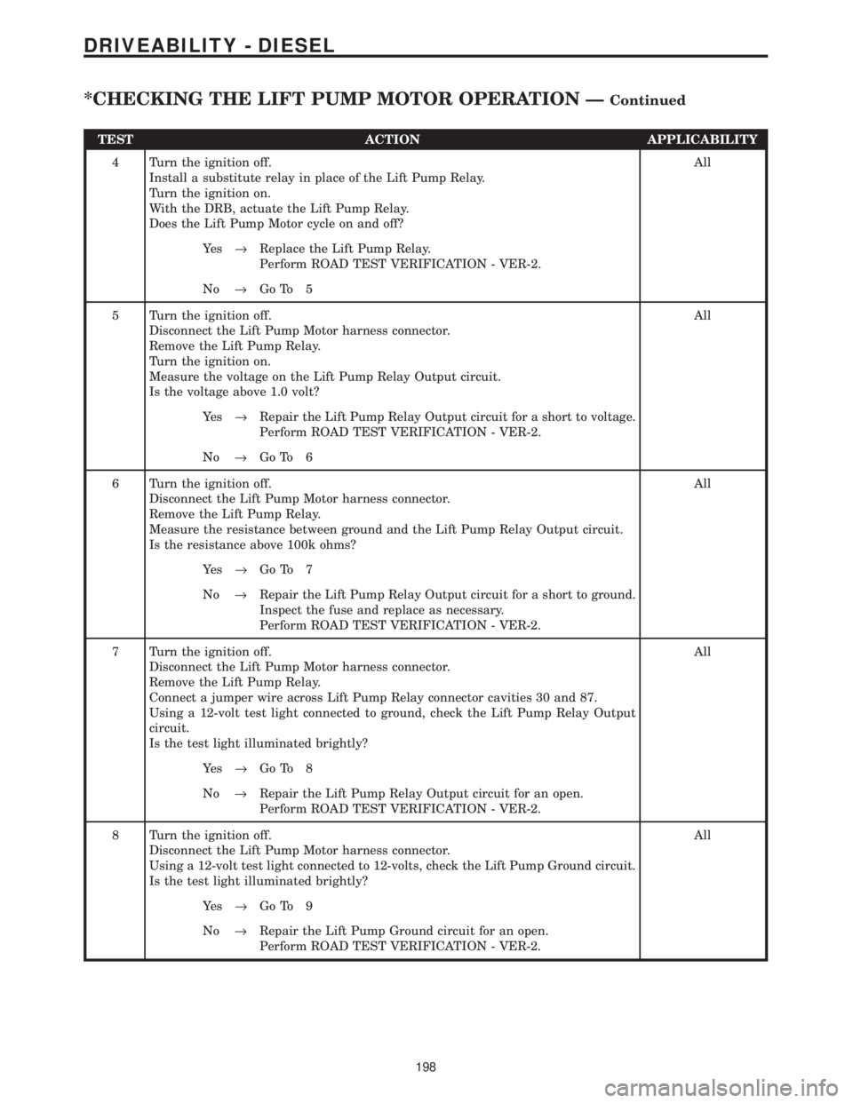
TEST ACTION APPLICABILITY
4 Turn the ignition off.
Install a substitute relay in place of the Lift Pump Relay.
Turn the ignition on.
With the DRB, actuate the Lift Pump Relay.
Does the Lift Pump Motor cycle on and off?All
Ye s®Replace the Lift Pump Relay.
Perform ROAD TEST VERIFICATION - VER-2.
No®Go To 5
5 Turn the ignition off.
Disconnect the Lift Pump Motor harness connector.
Remove the Lift Pump Relay.
Turn the ignition on.
Measure the voltage on the Lift Pump Relay Output circuit.
Is the voltage above 1.0 volt?All
Ye s®Repair the Lift Pump Relay Output circuit for a short to voltage.
Perform ROAD TEST VERIFICATION - VER-2.
No®Go To 6
6 Turn the ignition off.
Disconnect the Lift Pump Motor harness connector.
Remove the Lift Pump Relay.
Measure the resistance between ground and the Lift Pump Relay Output circuit.
Is the resistance above 100k ohms?All
Ye s®Go To 7
No®Repair the Lift Pump Relay Output circuit for a short to ground.
Inspect the fuse and replace as necessary.
Perform ROAD TEST VERIFICATION - VER-2.
7 Turn the ignition off.
Disconnect the Lift Pump Motor harness connector.
Remove the Lift Pump Relay.
Connect a jumper wire across Lift Pump Relay connector cavities 30 and 87.
Using a 12-volt test light connected to ground, check the Lift Pump Relay Output
circuit.
Is the test light illuminated brightly?All
Ye s®Go To 8
No®Repair the Lift Pump Relay Output circuit for an open.
Perform ROAD TEST VERIFICATION - VER-2.
8 Turn the ignition off.
Disconnect the Lift Pump Motor harness connector.
Using a 12-volt test light connected to 12-volts, check the Lift Pump Ground circuit.
Is the test light illuminated brightly?All
Ye s®Go To 9
No®Repair the Lift Pump Ground circuit for an open.
Perform ROAD TEST VERIFICATION - VER-2.
198
DRIVEABILITY - DIESEL
*CHECKING THE LIFT PUMP MOTOR OPERATION ÐContinued
Page 1429 of 4284

Symptom:
*ENGINE WILL NOT CRANK
POSSIBLE CAUSES
BATTERY CABLE HIGH RESISTANCE
CHECKING FOR SKIM CODES
CLUTCH INTERLOCK SWITCH
CLUTCH INTERLOCK SWITCH OUTPUT CIRCUIT
ECM
IGNITION SWITCH START OUTPUT CIRCUIT OPEN
IGNITION SWITCH START OUTPUT CIRCUIT OPEN
INSPECT BATTERY CABLES
MECHANICAL PROBLEM
OPEN FUSED BATTERY (+) CIRCUIT
STARTER MOTOR
STARTER RELAY
STARTER RELAY CONTROL CIRCUIT OPEN
STARTER RELAY CONTROL CIRCUIT SHORTED TO VOLTAGE
STARTER RELAY OUTPUT CIRCUIT OPEN
TEST ACTION APPLICABILITY
1 Turn the ignition off.
NOTE: The battery must be fully charged before diagnosing a no crank
condition.
Inspect the battery cables for corrosion, looseness or other problems.
Is there evidence of problems?All
Ye s®Repair as necessary.
Perform NO START VERIFICATION - VER-1.
No®Go To 2
2 Turn the ignition on.
With the DRBIIIt, read the SKIM DTCs.
Does the DRBIIItdisplay any SKIM DTCs?All
Ye s®Refer to symptom list for problems related to SKIM.
Perform NO START VERIFICATION - VER-1.
No®Go To 3
210
DRIVEABILITY - DIESEL
Page 1432 of 4284

TEST ACTION APPLICABILITY
11 Remove the Starter Relay from the PDC.
Using a 12-volt test light connected to ground, check the Fused B+ circuit.
Is the test light on?All
Ye s®Go To 12
No®Repair the Fused B(+) circuit for an open.
Perform NO START VERIFICATION - VER-1.
12 Turn the ignition off.
Remove the Starter Relay from the PDC.
Disconnect the Starter Relay Output wire from the Starter Solenoid.
Connect the Starter Relay Output wire (at the Starter) to ground.
Using a 12-volt test light connected to 12-volts, check the Starter Relay Output
circuit at the Starter Relay connector in the IPM.
Does the test light illuminate brightly?All
Ye s®Go To 13
No®Repair the Starter Relay Output circuit for an open.
Perform NO START VERIFICATION - VER-1.
13 Using the Service Information, check the battery cables for high resistance.
Did either battery cable have a voltage drop greater than 0.2 volts?All
Ye s®Replace the battery cable(s).
Perform NO START VERIFICATION - VER-1.
No®Go To 14
14 Turn the ignition off.
Attempt to manually rotate the crankshaft 360É.
Is the crankshaft able to rotate 360É?All
Ye s®Replace the Starter Motor.
Perform NO START VERIFICATION - VER-1.
No®Repair the engine mechanical problem.
Perform NO START VERIFICATION - VER-1.
213
DRIVEABILITY - DIESEL
*ENGINE WILL NOT CRANK ÐContinued
Page 1451 of 4284
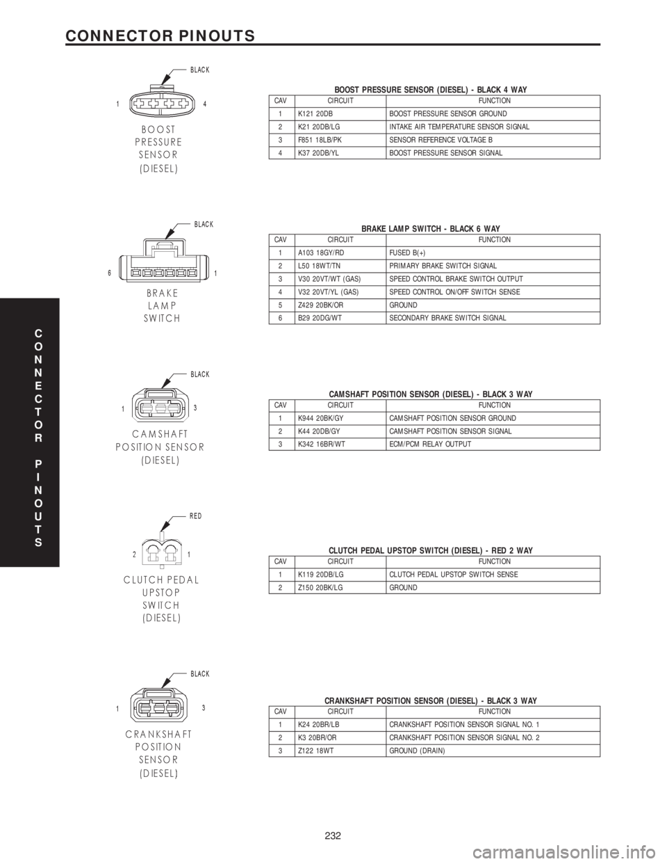
BOOST PRESSURE SENSOR (DIESEL) - BLACK 4 WAYCAV CIRCUIT FUNCTION
1 K121 20DB BOOST PRESSURE SENSOR GROUND
2 K21 20DB/LG INTAKE AIR TEMPERATURE SENSOR SIGNAL
3 F851 18LB/PK SENSOR REFERENCE VOLTAGE B
4 K37 20DB/YL BOOST PRESSURE SENSOR SIGNAL
BRAKE LAMP SWITCH - BLACK 6 WAYCAV CIRCUIT FUNCTION
1 A103 18GY/RD FUSED B(+)
2 L50 18WT/TN PRIMARY BRAKE SWITCH SIGNAL
3 V30 20VT/WT (GAS) SPEED CONTROL BRAKE SWITCH OUTPUT
4 V32 20VT/YL (GAS) SPEED CONTROL ON/OFF SWITCH SENSE
5 Z429 20BK/OR GROUND
6 B29 20DG/WT SECONDARY BRAKE SWITCH SIGNAL
CAMSHAFT POSITION SENSOR (DIESEL) - BLACK 3 WAYCAV CIRCUIT FUNCTION
1 K944 20BK/GY CAMSHAFT POSITION SENSOR GROUND
2 K44 20DB/GY CAMSHAFT POSITION SENSOR SIGNAL
3 K342 16BR/WT ECM/PCM RELAY OUTPUT
CLUTCH PEDAL UPSTOP SWITCH (DIESEL) - RED 2 WAYCAV CIRCUIT FUNCTION
1 K119 20DB/LG CLUTCH PEDAL UPSTOP SWITCH SENSE
2 Z150 20BK/LG GROUND
CRANKSHAFT POSITION SENSOR (DIESEL) - BLACK 3 WAYCAV CIRCUIT FUNCTION
1 K24 20BR/LB CRANKSHAFT POSITION SENSOR SIGNAL NO. 1
2 K3 20BR/OR CRANKSHAFT POSITION SENSOR SIGNAL NO. 2
3 Z122 18WT GROUND (DRAIN)
C
O
N
N
E
C
T
O
R
P
I
N
O
U
T
S
232
CONNECTOR PINOUTS
Page 1452 of 4284
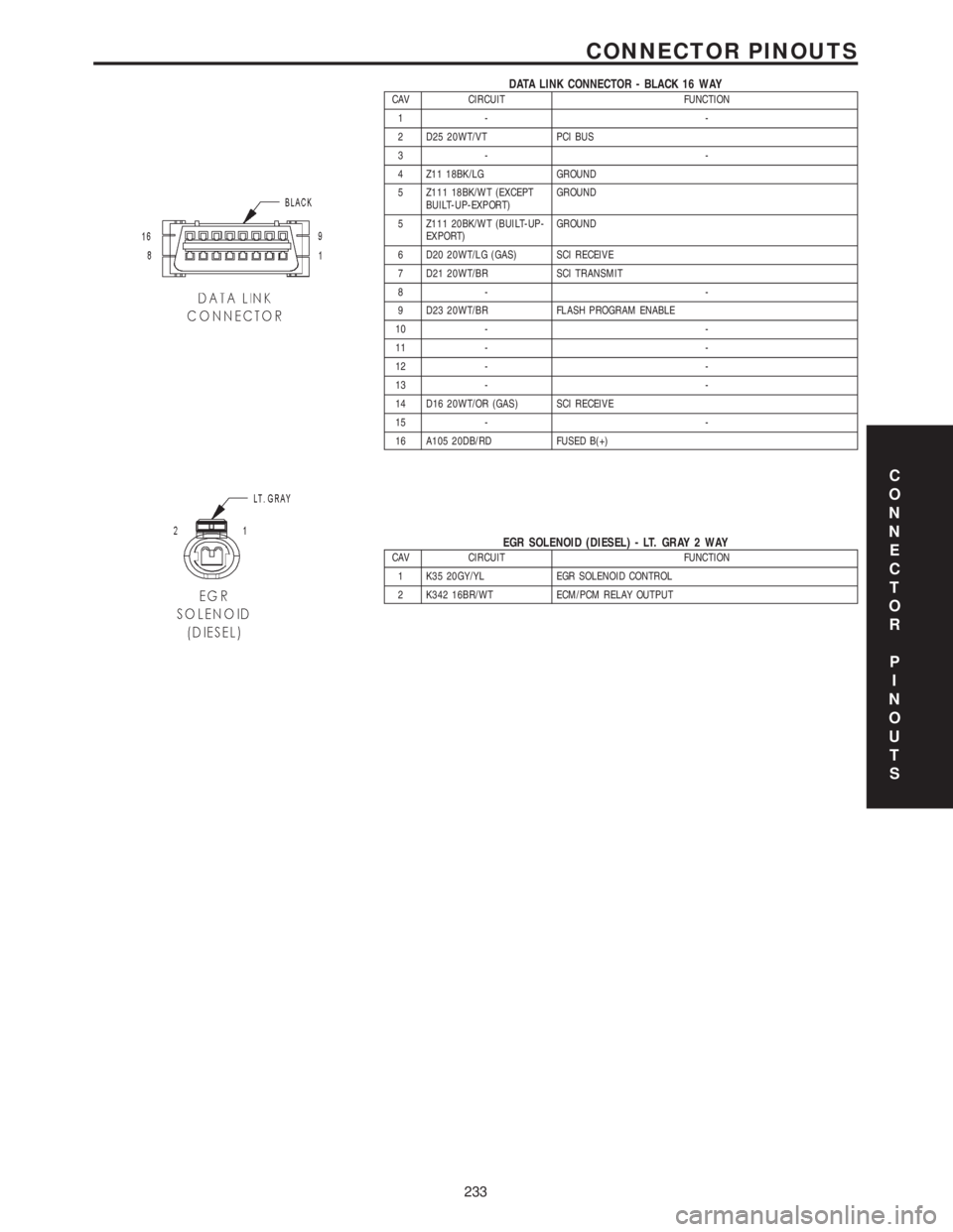
DATA LINK CONNECTOR - BLACK 16 WAYCAV CIRCUIT FUNCTION
1- -
2 D25 20WT/VT PCI BUS
3- -
4 Z11 18BK/LG GROUND
5 Z111 18BK/WT (EXCEPT
BUILT-UP-EXPORT)GROUND
5 Z111 20BK/WT (BUILT-UP-
EXPORT)GROUND
6 D20 20WT/LG (GAS) SCI RECEIVE
7 D21 20WT/BR SCI TRANSMIT
8- -
9 D23 20WT/BR FLASH PROGRAM ENABLE
10 - -
11 - -
12 - -
13 - -
14 D16 20WT/OR (GAS) SCI RECEIVE
15 - -
16 A105 20DB/RD FUSED B(+)
EGR SOLENOID (DIESEL) - LT. GRAY 2 WAYCAV CIRCUIT FUNCTION
1 K35 20GY/YL EGR SOLENOID CONTROL
2 K342 16BR/WT ECM/PCM RELAY OUTPUT
C
O
N
N
E
C
T
O
R
P
I
N
O
U
T
S
233
CONNECTOR PINOUTS
Page 1458 of 4284

GLOW PLUG RELAY (DIESEL) - BLACK 4 WAYCAV CIRCUIT FUNCTION
1 A202 10RD/WT FUSED B(+)
2 K152 20DB/WT GLOW PLUG RELAY CONTROL
3 K342 16BR/WT ECM/PCM RELAY OUTPUT
4 K154 10BR/OR GLOW PLUG RELAY OUTPUT
INTELLIGENT POWER MODULE C3 (DIESEL) - YELLOW/RED 20 WAYCAV CIRCUIT FUNCTION
1 N21 20DB/TN LIFT PUMP RELAY CONTROL
2- -
3 T751 20YL IGNITION SWITCH OUTPUT (START)
4 T2 18DG/WT TRS REVERSE SENSE
5 N2 18DB/YL LIFT PUMP RELAY OUTPUT
6 F202 18PK/GY IGNITION SWITCH OUTPUT (RUN-START)
7 C3 18DB/YL A/C COMPRESSOR CLUTCH RELAY OUTPUT
8 Z114 18BK/LG GROUND
9 C13 20LB/OR A/C COMPRESSOR CLUTCH RELAY CONTROL
10 A119 16RD/OR FUSED B(+)
11 C41 20LB/DG CABIN HEATER ASSIST CONTROL
12 T753 20DG/YL IGNITION SWITCH OUTPUT (START)
13 - -
14 T752 20DG/OR ENGINE STARTER MOTOR RELAY CONTROL
15 Z116 18BK/VT GROUND
16 K51 20BR/WT ECM/PCM RELAY CONTROL
17 F202 18PK/GY IGNITION SWITCH OUTPUT (RUN-START)
18 - -
19 K342 16BR/WT ECM/PCM RELAY OUTPUT
20 - -
LEFT SPEED CONTROL SWITCH - WHITE 2 WAYCAV CIRCUIT FUNCTION
A V37 20VT/TN (BUILT-UP-
EXPORT)SPEED CONTROL SWITCH SIGNAL
A V37 20DG/VT (EXCEPT
BUILT-UP-EXPORT)SPEED CONTROL SWITCH SIGNAL
B Z23 20BK/VT LEFT SPEED CONTROL SWITCH GROUND
LIFT PUMP MOTOR (DIESEL) - BLACK 2 WAYCAV CIRCUIT FUNCTION
1 N2 18OR LIFT PUMP RELAY OUTPUT
2 Z201 18OR GROUND
C
O
N
N
E
C
T
O
R
P
I
N
O
U
T
S
239
CONNECTOR PINOUTS
Page 1461 of 4284

A/C COMPRESSOR CLUTCH RELAYCAV CIRCUIT FUNCTION
30 INTERNAL FUSED B(+)
85 C13 18LB/OR (GAS) A/C COMPRESSOR CLUTCH RELAY CONTROL
85 C13 20LB/OR (DIESEL) A/C COMPRESSOR CLUTCH RELAY CONTROL
86 F202 18PK/GY (GAS) IGNITION SWITCH OUTPUT (RUN-START)
86 K342 16BR/WT (DIESEL) ECM/PCM RELAY OUTPUT
87 C3 18DB/YL A/C COMPRESSOR CLUTCH RELAY OUTPUT
87A --
ECM/PCM RELAY (DIESEL)CAV CIRCUIT FUNCTION
30 INTERNAL FUSED B(+)
85 K51 20BR/WT ECM/PCM RELAY CONTROL
86 INTERNAL FUSED B(+)
87 K342 16BR/WT ECM/PCM RELAY OUTPUT
87A --
FUEL HEATER RELAY (DIESEL)CAV CIRCUIT FUNCTION
30 INTERNAL FUSED B(+)
85 Z114 18BK/LG GROUND
86 INTERNAL IGNITION SWITCH OUTPUT (RUN-START)
87 N1 16DB/OR FUEL HEATER RELAY OUTPUT
87A --
LIFT PUMP RELAY (DIESEL)CAV CIRCUIT FUNCTION
30 INTERNAL FUSED B(+)
85 N21 20DB/TN LIFT PUMP RELAY CONTROL
86 F202 18PK/GY FUSED IGNITION SWITCH OUTPUT (RUN-START)
87 N2 18DB/YL LIFT PUMP RELAY OUTPUT
87A --
STARTER MOTOR RELAYCAV CIRCUIT FUNCTION
30 INTERNAL FUSED B(+)
85 T752 18DG/OR (GAS) ENGINE STARTER MOTOR RELAY CONTROL
85 T752 20DG/OR (DIESEL) ENGINE STARTER MOTOR RELAY CONTROL
86 INTERNAL IGNITION SWITCH OUTPUT (START)
87 T750 12YL/GY ENGINE STARTER MOTOR RELAY OUTPUT
87A --
RADIATOR FAN NO. 1 (DIESEL) - GRAY 2 WAYCAV CIRCUIT FUNCTION
1 N202 12DB/OR RADIATOR FAN NO. 1 CONTROL
2 N201 12DB/LG RADIATOR FAN RELAY NO. 1 OUTPUT
C
O
N
N
E
C
T
O
R
P
I
N
O
U
T
S
242
CONNECTOR PINOUTS