fuse CHRYSLER VOYAGER 2001 Service Manual
[x] Cancel search | Manufacturer: CHRYSLER, Model Year: 2001, Model line: VOYAGER, Model: CHRYSLER VOYAGER 2001Pages: 4284, PDF Size: 83.53 MB
Page 1112 of 4284
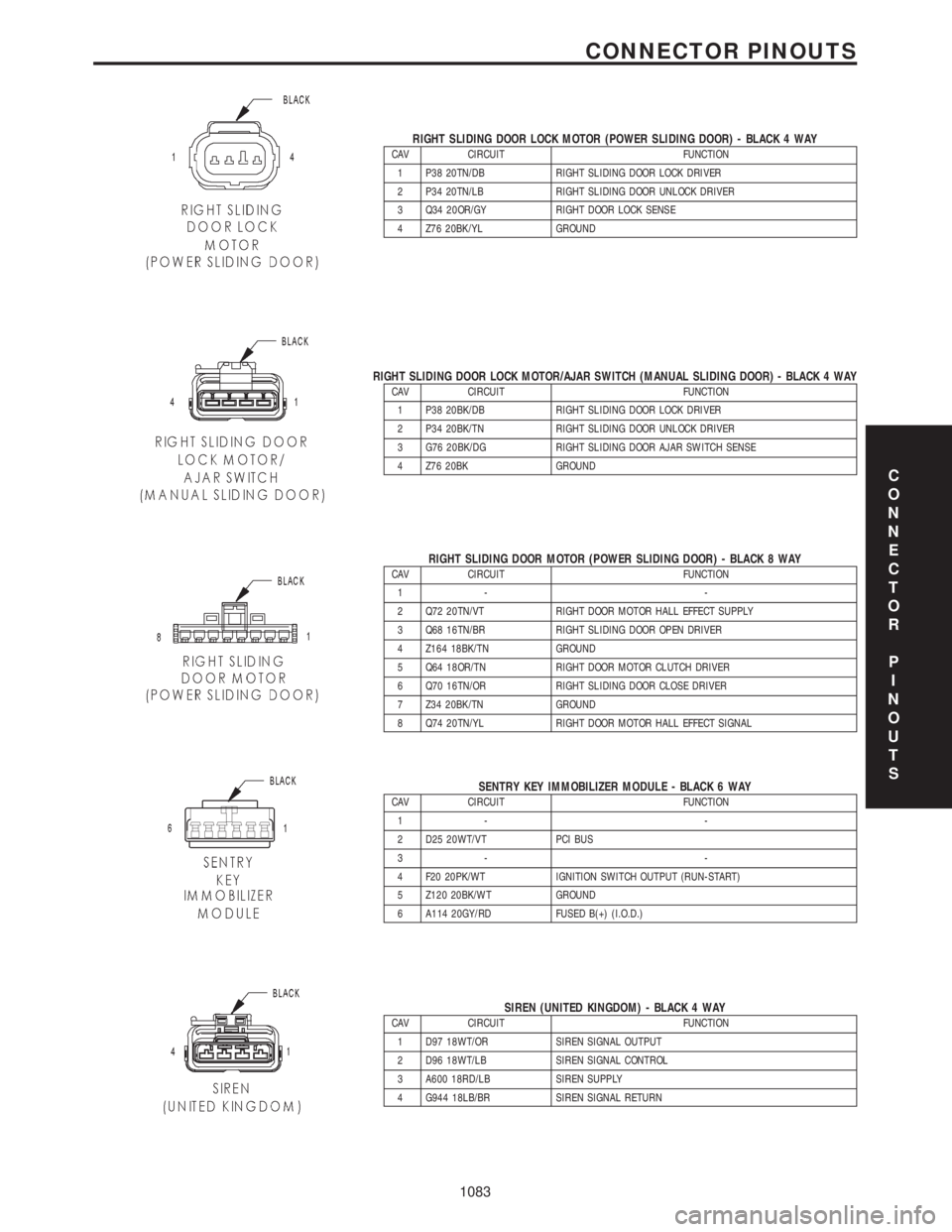
RIGHT SLIDING DOOR LOCK MOTOR (POWER SLIDING DOOR) - BLACK 4 WAYCAV CIRCUIT FUNCTION
1 P38 20TN/DB RIGHT SLIDING DOOR LOCK DRIVER
2 P34 20TN/LB RIGHT SLIDING DOOR UNLOCK DRIVER
3 Q34 20OR/GY RIGHT DOOR LOCK SENSE
4 Z76 20BK/YL GROUND
RIGHT SLIDING DOOR LOCK MOTOR/AJAR SWITCH (MANUAL SLIDING DOOR) - BLACK 4 WAYCAV CIRCUIT FUNCTION
1 P38 20BK/DB RIGHT SLIDING DOOR LOCK DRIVER
2 P34 20BK/TN RIGHT SLIDING DOOR UNLOCK DRIVER
3 G76 20BK/DG RIGHT SLIDING DOOR AJAR SWITCH SENSE
4 Z76 20BK GROUND
RIGHT SLIDING DOOR MOTOR (POWER SLIDING DOOR) - BLACK 8 WAYCAV CIRCUIT FUNCTION
1- -
2 Q72 20TN/VT RIGHT DOOR MOTOR HALL EFFECT SUPPLY
3 Q68 16TN/BR RIGHT SLIDING DOOR OPEN DRIVER
4 Z164 18BK/TN GROUND
5 Q64 18OR/TN RIGHT DOOR MOTOR CLUTCH DRIVER
6 Q70 16TN/OR RIGHT SLIDING DOOR CLOSE DRIVER
7 Z34 20BK/TN GROUND
8 Q74 20TN/YL RIGHT DOOR MOTOR HALL EFFECT SIGNAL
SENTRY KEY IMMOBILIZER MODULE - BLACK 6 WAYCAV CIRCUIT FUNCTION
1- -
2 D25 20WT/VT PCI BUS
3- -
4 F20 20PK/WT IGNITION SWITCH OUTPUT (RUN-START)
5 Z120 20BK/WT GROUND
6 A114 20GY/RD FUSED B(+) (I.O.D.)
SIREN (UNITED KINGDOM) - BLACK 4 WAYCAV CIRCUIT FUNCTION
1 D97 18WT/OR SIREN SIGNAL OUTPUT
2 D96 18WT/LB SIREN SIGNAL CONTROL
3 A600 18RD/LB SIREN SUPPLY
4 G944 18LB/BR SIREN SIGNAL RETURN
C
O
N
N
E
C
T
O
R
P
I
N
O
U
T
S
1083
CONNECTOR PINOUTS
Page 1113 of 4284
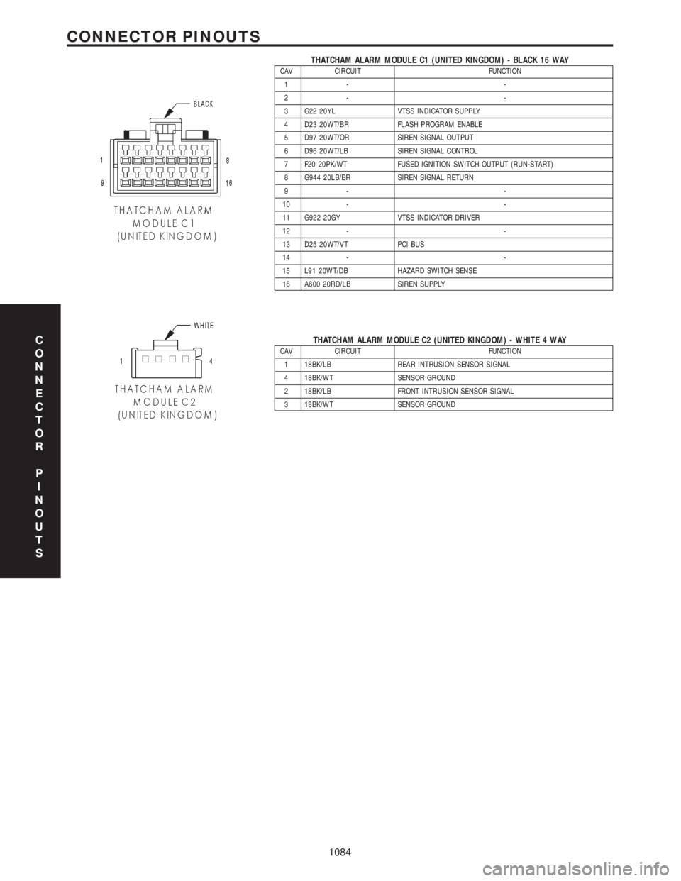
THATCHAM ALARM MODULE C1 (UNITED KINGDOM) - BLACK 16 WAYCAV CIRCUIT FUNCTION
1- -
2- -
3 G22 20YL VTSS INDICATOR SUPPLY
4 D23 20WT/BR FLASH PROGRAM ENABLE
5 D97 20WT/OR SIREN SIGNAL OUTPUT
6 D96 20WT/LB SIREN SIGNAL CONTROL
7 F20 20PK/WT FUSED IGNITION SWITCH OUTPUT (RUN-START)
8 G944 20LB/BR SIREN SIGNAL RETURN
9- -
10 - -
11 G922 20GY VTSS INDICATOR DRIVER
12 - -
13 D25 20WT/VT PCI BUS
14 - -
15 L91 20WT/DB HAZARD SWITCH SENSE
16 A600 20RD/LB SIREN SUPPLY
THATCHAM ALARM MODULE C2 (UNITED KINGDOM) - WHITE 4 WAYCAV CIRCUIT FUNCTION
1 18BK/LB REAR INTRUSION SENSOR SIGNAL
4 18BK/WT SENSOR GROUND
2 18BK/LB FRONT INTRUSION SENSOR SIGNAL
3 18BK/WT SENSOR GROUNDC
O
N
N
E
C
T
O
R
P
I
N
O
U
T
S
1084
CONNECTOR PINOUTS
Page 1114 of 4284
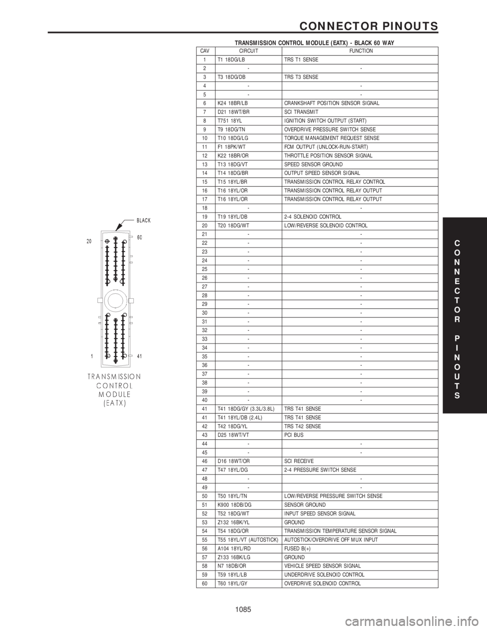
TRANSMISSION CONTROL MODULE (EATX) - BLACK 60 WAYCAV CIRCUIT FUNCTION
1 T1 18DG/LB TRS T1 SENSE
2- -
3 T3 18DG/DB TRS T3 SENSE
4- -
5- -
6 K24 18BR/LB CRANKSHAFT POSITION SENSOR SIGNAL
7 D21 18WT/BR SCI TRANSMIT
8 T751 18YL IGNITION SWITCH OUTPUT (START)
9 T9 18DG/TN OVERDRIVE PRESSURE SWITCH SENSE
10 T10 18DG/LG TORQUE MANAGEMENT REQUEST SENSE
11 F1 18PK/WT FCM OUTPUT (UNLOCK-RUN-START)
12 K22 18BR/OR THROTTLE POSITION SENSOR SIGNAL
13 T13 18DG/VT SPEED SENSOR GROUND
14 T14 18DG/BR OUTPUT SPEED SENSOR SIGNAL
15 T15 18YL/BR TRANSMISSION CONTROL RELAY CONTROL
16 T16 18YL/OR TRANSMISSION CONTROL RELAY OUTPUT
17 T16 18YL/OR TRANSMISSION CONTROL RELAY OUTPUT
18 - -
19 T19 18YL/DB 2-4 SOLENOID CONTROL
20 T20 18DG/WT LOW/REVERSE SOLENOID CONTROL
21 - -
22 - -
23 - -
24 - -
25 - -
26 - -
27 - -
28 - -
29 - -
30 - -
31 - -
32 - -
33 - -
34 - -
35 - -
36 - -
37 - -
38 - -
39 - -
40 - -
41 T41 18DG/GY (3.3L/3.8L) TRS T41 SENSE
41 T41 18YL/DB (2.4L) TRS T41 SENSE
42 T42 18DG/YL TRS T42 SENSE
43 D25 18WT/VT PCI BUS
44 - -
45 - -
46 D16 18WT/OR SCI RECEIVE
47 T47 18YL/DG 2-4 PRESSURE SWITCH SENSE
48 - -
49 - -
50 T50 18YL/TN LOW/REVERSE PRESSURE SWITCH SENSE
51 K900 18DB/DG SENSOR GROUND
52 T52 18DG/WT INPUT SPEED SENSOR SIGNAL
53 Z132 16BK/YL GROUND
54 T54 18DG/OR TRANSMISSION TEMPERATURE SENSOR SIGNAL
55 T55 18YL/VT (AUTOSTICK) AUTOSTICK/OVERDRIVE OFF MUX INPUT
56 A104 18YL/RD FUSED B(+)
57 Z133 16BK/LG GROUND
58 N7 18DB/OR VEHICLE SPEED SENSOR SIGNAL
59 T59 18YL/LB UNDERDRIVE SOLENOID CONTROL
60 T60 18YL/GY OVERDRIVE SOLENOID CONTROL
C
O
N
N
E
C
T
O
R
P
I
N
O
U
T
S
1085
CONNECTOR PINOUTS
Page 1115 of 4284
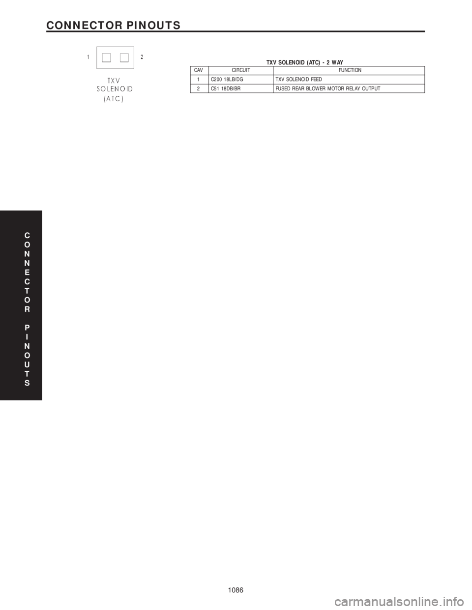
TXV SOLENOID (ATC)-2WAYCAV CIRCUIT FUNCTION
1 C200 18LB/DG TXV SOLENOID FEED
2 C51 18DB/BR FUSED REAR BLOWER MOTOR RELAY OUTPUT
C
O
N
N
E
C
T
O
R
P
I
N
O
U
T
S
1086
CONNECTOR PINOUTS
Page 1157 of 4284

TABLE OF CONTENTS - Continued
RIGHT REAR WHEEL SPEED SIGNAL FAILURE.............................26
SYSTEM OVERVOLTAGE................................................28
SYSTEM UNDERVOLTAGE...............................................30
VALVE POWER FEED FAILURE...........................................32
*BRAKE LAMP SWITCH..................................................35
*TRAC OFF INDICATOR NEVER/ALWAYS ON...............................36
*TRAC ON INDICATOR NEVER/ALWAYS ON................................39
VERIFICATION TESTS
VERIFICATION TESTS...................................................40
8.0 COMPONENT LOCATIONS...............................................41
8.1CONTROLLER ANTILOCK BRAKE (CAB)..............................41
8.2DATA LINK CONNECTOR...........................................41
8.3FUSES...........................................................42
8.4TRACTION CONTROL SWITCH......................................42
8.4.1TRACTION CONTROL INDICATORS...........................43
8.5WHEEL SPEED SENSORS..........................................43
8.5.1FRONT....................................................43
8.5.2REAR.....................................................44
8.5AWHEEL SPEED SENSOR CONNECTORS..............................44
8.5A.1FRONT....................................................44
8.5A.2REAR.....................................................45
8.6BRAKE LAMP SWITCH.............................................45
9.0 CONNECTOR PINOUTS.................................................47
CONTROLLER ANTILOCK BRAKE - BLACK 24 WAY..........................47
DATA LINK CONNECTOR - WHITE 16 WAY.................................47
DIAGNOSTIC JUNCTION PORT - BLACK 16 WAY............................48
INTELLIGENT POWER MODULE C4 - GRAY 10 WAY.........................48
LEFT FRONT WHEEL SPEED SENSOR - BLACK 2 WAY......................48
LEFT FRONT WHEEL SPEED SENSOR CONNECTOR (SENSOR SIDE)-2WAY..49
LEFT REAR WHEEL SPEED SENSOR - BLACK 2 WAY........................49
LEFT REAR WHEEL SPEED SENSOR CONNECTOR (SENSOR SIDE)-2WAY ...49
FUSES (IPM)...........................................................51
PUMP MOTOR CONNECTOR-2WAY.....................................52
RIGHT FRONT WHEEL SPEED SENSOR - GRAY 2 WAY......................52
RIGHT FRONT WHEEL SPEED SENSOR CONNECTOR
(SENSOR SIDE)-2WAY.................................................52
RIGHT REAR WHEEL SPEED SENSOR - BLACK 2 WAY......................52
RIGHT REAR WHEEL SPEED SENSOR CONNECTOR (SENSOR SIDE)-2WAY..53
TRACTION CONTROL SWITCH - BLACK 2 WAY.............................53
10.0 SCHEMATIC DIAGRAMS.................................................55
TEVES MARK 20 ANTILOCK BRAKE SYSTEM........................55
ii
Page 1159 of 4284
The cycling of the build and decay valves is
similar to the ABS except that they work to control
wheel spin by applying brakes. ABS function is to
control wheel skid by releasing brakes.
Two pressure relief valves allow excess fluid vol-
ume to return to the reservoir when not used by the
build/decay cycles. These are required because the
pump supplies more volume than the traction con-
trol system requires.
If at any time the brake pedal is applied during a
traction control cycle, the brake lamp switch will
trigger the CAB to switch off the traction control.
The traction control system will be enabled at
each ignition cycle. It may be turned off by depress-
ing the Traction Control Switch. The traction con-
trol system function lamp will illuminate ªTRAC
OFFº immediately upon depressing the traction
control switch button. Only the ªTRACº portion of
the ªTRAC OFFº indicator will illuminate during a
traction control event. If the CAB calculates that
the brake temperatures are high, the traction con-
trol system will become inoperative until a time-out
period has elapsed. When in this thermal protection
mode, the traction control ªTRAC OFFº lamp will
illuminate; however, a fault will not be registered.
3.3 SYSTEM COMPONENTS
²controller antilock brake (CAB)
²vacuum booster
²master cylinder
²ABS integrated electronic control module/
hydraulic control unit (HCU), valve block assem-
bly: 8 valve solenoids (4 inlet valves, 4 outlet
valves, 2 accumulators) 1 motor, 2 pump
²ABS integrated electronic control module with
traction control same as above but has 10 valve
solenoids.
²4 wheel speed sensor/tone wheel assemblies
²ABS warning indicator
²fuses and wiring harness
²fluid reservoir
²TRAC/TRAC OFF indicator
3.3.1 ABS AND BRAKE WARNING
INDICATORS
The amber ABS warning indicator is located in
the instrument cluster. It is used to inform the
driver that the antilock function has been turned
off. The ABS warning indicator is controlled by the
CAB. The CAB controls the lamp with a command
over the PCI bus.
The ABS Warning Indicator will remain lit during
every key cycle until a circuit or component fault is
repaired and the CAB no longer detects the fault.After repair of a sensor signal fault or a pump motor
fault, the CAB must sense all four wheels at 25
km/h (15 mph) before it will extinguish the ABS and
TRAC OFF Indicators.
The Instrument Cluster will illuminate the ABS
Warning Indicator if it loses communication with
the CAB.
The red BRAKE warning indicator is also located
in the instrument cluster. It can be activated in
several ways. Application of the parking brake or a
low fluid signal from the fluid level switch located in
the master cylinder reservoir will cause the indica-
tor to come on.
3.3.2 CONTROLLER ANTILOCK BRAKE
(CAB)
The Controller Antilock Brake (CAB) is a
microprocessor-based device that monitors wheel
speeds and controls the antilock functions. The
CAB contains two microprocessors that receive
identical sensor signals and then independently
process the information. The results are then com-
pared to make sure that they agree. Otherwise, the
CAB will turn off the antilock and turn on the ABS
amber warning indicator.
The primary functions of the CAB are to:
²detect wheel locking tendencies
²control fluid pressure modulation to the brakes
during antilock stop
²monitor the system for proper operation
²manage traction control functions
²provide communication to the DRBIIItwhile in
diagnostic mode
²store diagnostic information in non-volatile memory
The CAB continuously monitors the speed of each
wheel. When a wheel locking tendency is detected,
the CAB will command the appropriate valve to
modulate brake fluid pressure in its hydraulic unit.
Brake pedal position is maintained during an an-
tilock stop by being a closed system with the use of
2 accumulators. The CAB continues to control pres-
sure in individual hydraulic circuits until a wheel
locking tendency is no longer present. The CAB
turns on the pump motor during an antilock stop.
The antilock brake system is constantly moni-
tored by the CAB for proper operation. If the CAB
detects a system malfunction, it can disable the
antilock system and turn on the ABS warning
indicator. If the antilock function is disabled, the
system will revert to standard base brake system
operation.
The CAB inputs include the following:
²diagnostic communication
²four wheel speed sensors
2
GENERAL INFORMATION
Page 1163 of 4284
4.3 WARNINGS
4.3.1 VEHICLE DAMAGE WARNINGS
Before disconnecting any control module, make
sure the ignition is ``off ''. Failure to do so could
damage the module.
When testing voltage or continuity at any control
module, use the terminal side (not the wire end) of
the connector. Do not probe a wire through the
insulation, this will damage it and eventually cause
it to fail because of corrosion.
Be careful when performing electrical tests so as
to prevent accidental shorting of terminals. Such
mistakes can damage fuses or components. Also, a
second code could be set, making diagnosis of the
original problem more difficult.
4.3.2 ROAD TESTING A COMPLAINT
VEHICLE
Some complaints will require a test drive as part
of the repair verification procedure. The purpose of
the test drive is to try to duplicate the diagnostic
code or symptom condition.
WARNING: BEFORE ROAD TESTING A
VEHICLE, BE SURE THAT ALL
COMPONENTS ARE REASSEMBLED.
DURING THE TEST DRIVE, DO NOT TRY TO
READ THE DRB SCREEN WHILE IN MOTION.
DO NOT HANG THE DRBIIITFROM THE
REAR VIEW MIRROR OR OPERATE IT
YOURSELF. HAVE AN ASSISTANT
AVAILABLE TO OPERATE THE DRBIIIT.
4.4 DIAGNOSIS
1. Your diagnostic test procedure must begin with a
thorough visual inspection of the ABS system for
damaged components or disconnected connec-
tors. The brake lamps must be operational, and
if they are not, repair them prior to continuing.
2. Connect the DRBIIItto the data link connector,
which is located under the dash to the left of the
steering column. If the DRBIIItdoes not power
up, check the power and ground supplies to the
connector.
3. Turn the ignition on. Select ªAntilock Brakesº. If
the DRBIIItdisplays ªNo Responseº condition
you must diagnose that first.
4. Read and record all ABS diagnostic trouble
codes. If the ªCAB Power Feed Circuitº diagnos-
tic trouble code is present, it must be repaired
prior to addressing any other DTC's. If any
additional DTC's are present, proceed to theappropriate test by locating the matching test in
the Table of Contents and begin to diagnose the
symptom.
5. If there are no diagnostic trouble codes present,
identify the customer complaint. Select ªInputs/
Outputsº and read the brake switch input as you
press and release the brake pedal. If the display
does not match the state of the pedal, perform
the proper test by locating the matching test in
the Table of Contents and begin to diagnose the
symptom. If a problem exists with the yellow
ªABSº warning indicator or the red ªBrakeº
indicator exists, refer to the proper tests by
locating the matching test in the Table of Con-
tents and begin to diagnose the symptom. Read
the traction control switch input as you press
and release the switch. If the display does not
match the state of the indicator perform the
proper test by locating the matching test in the
Table of Contents and begin to diagnose the
symptom.
6. If no other problems are found, it will be neces-
sary to road test the vehicle. Perform several
antilock stops from above 50 Km/h (30 mph) and
then repeat step 4. If any diagnostic trouble
codes are present, proceed to the appropriate test.
7. The following conditions should be considered
ªNORMALº operation, and no repairs should be
attempted to correct them.
± Brake pedal feedback during an ABS stop
(clicking, vibrating).
± Clicking, groaning or buzzing at 25 Km/h (15
mph) or 40 Km/h (24 mph) (drive off self test).
± Groaning noise during an ABS stop.
± Slight brake pedal drop and pop noise when
ignition is initially turned on.
± Brake pedal ratcheting down at the end of an
ABS stop.
8. If the complaint is ABS ªcyclingº at the end of a
stop at low speeds, it may be caused by a
marginal wheel speed sensor signal. The sensor
air gap, tone wheel condition, and/or brakes
hanging up are possible causes of this condition.
9. After a road test in which no problems were
found, refer to any Technical Service Bulletins
that may apply.
5.0 REQUIRED TOOLS AND
EQUIPMENT
DRBIIIt(diagnostic read-out box)
jumper wires
ohmmeter
voltmeter
test light
6
GENERAL INFORMATION
Page 1169 of 4284

Symptom:
CLUSTER LAMP FAILURE
When Monitored and Set Condition:
CLUSTER LAMP FAILURE
When Monitored: Key ON. After Key-ON bulb check.
Set Condition: When the instrument cluster informs the CAB that the cluster cannot
turn on the ABS Lamp.
POSSIBLE CAUSES
CLUSTER DTC PRESENT
CLUSTER INTERNAL FAULT
CAB -- NO ABS INDICATOR MESSAGE
CAB -- ABS INDICATOR FAULT
TEST ACTION APPLICABILITY
1 Turn the ignition on.
With the DRBIIIt, read DTCs.
Are there any Instrument Cluster DTCs present?All
Ye s®Refer to the INSTRUMENT CLUSTER category for the related
symptom(s).
Perform ABS VERIFICATION TEST - VER 1.
No®Go To 2
2 Turn the ignition off.
Observe the instrument cluster indicators.
Turn the ignition on.
Did the ABS Indicator illuminate for several seconds and then go out?All
Ye s®Go To 3
No®Go To 4
3NOTE: The DRBIIItcommunication with the CAB must be operational for
the result of this test to be valid.
Turn the ignition off.
Remove Fuse 21 (ABS valve power) from the IPM.
Perform the Key-on Bulb Check.
Does the ABS Indicator remain on after the bulb check?All
Ye s®Test Complete.
No®Replace the Controller Antilock Brake in accordance with the
Service Information.
Perform ABS VERIFICATION TEST - VER 1.
12
BRAKES (CAB)
Page 1178 of 4284

Symptom:
PUMP CIRCUIT FAILURE
When Monitored and Set Condition:
PUMP CIRCUIT FAILURE
When Monitored: Ignition on. The CAB commands the pump on at 20 km/h (12 mph) to
check its operation, if the brake switch is not applied. If the brake is applied, the test will
run at 40 km/h (25 mph). The CAB monitors pump voltage every 7 milliseconds.
Set Condition: The DTC is stored when the CAB detects: 1) Improper voltage decay after
the pump was turned off. 2) Pump not energized by the CAB, but voltage is present for 3.5
seconds. 3) Pump is turned on by the CAB, but without sufficient voltage to operate it.
POSSIBLE CAUSES
PUMP HARNESS DISCONNECTED
CAB - PUMP MOTOR RUNNING CONTINUOUSLY
ABS PUMP MOTOR INTERMITTENT DTC
GROUND CIRCUIT HIGH RESISTANCE
FUSED B(+) CIRCUIT OPEN
GROUND CIRCUIT OPEN
CAB - INTERNAL FAULT
CAB - SETTING FALSE CODE
TEST ACTION APPLICABILITY
1 Turn the ignition off.
Turn the ignition on.
Monitor the pump motor for continuous operation.
Is the pump motor running continuously?All
Ye s®Replace the Controller Anti-Lock Brake in accordance with the
Service Information. The vehicle must be driven at 25 km/h (15
mph) to extinguish the ABS indicator.
Perform ABS VERIFICATION TEST - VER 1.
No®Go To 2
2 Turn the ignition on.
With the DRBIIIt, read DTC's.
With the DRBIIIt, erase DTC's.
Turn the ignition off.
Turn the ignition on.
With the DRBIIIt, actuate the ABS pump motor.
Did the Pump Motor operate when actuated?All
Ye s®Go To 3
No®Go To 4
21
BRAKES (CAB)
Page 1180 of 4284

TEST ACTION APPLICABILITY
7 Turn the ignition off.
Disconnect the CAB connector.
Note: Check connector - Clean/repair as necessary.
Turn the ignition on.
Using a 12-volt test light connected to ground, check the Pump Motor Fused B+
circuit.
Does the test light illuminate brightly?All
Ye s®Go To 8
No®Repair the Fused B(+) circuit for an open. The vehicle must be
driven at 25 km/h (15 mph) to extinguish the ABS indicator.
Perform ABS VERIFICATION TEST - VER 1.
8 If there are no possible causes remaining, view repair. All
Repair
Replace the Controller Anti-Lock Brake in accordance with the
Service Information. The vehicle must be driven at 25 km/h (15
mph) to extinguish the ABS indicator.
Perform ABS VERIFICATION TEST - VER 1.
23
BRAKES (CAB)
PUMP CIRCUIT FAILURE ÐContinued