fuse CHRYSLER VOYAGER 2001 Service Manual
[x] Cancel search | Manufacturer: CHRYSLER, Model Year: 2001, Model line: VOYAGER, Model: CHRYSLER VOYAGER 2001Pages: 4284, PDF Size: 83.53 MB
Page 1185 of 4284

Symptom:
SYSTEM OVERVOLTAGE
When Monitored and Set Condition:
SYSTEM OVERVOLTAGE
When Monitored: Ignition on. The CAB monitors the Fused B(+) circuit at all times for
proper system voltage.
Set Condition: If the voltage is above 16.5 volts for greater than 420 milliseconds (ms),
the Diagnostic Trouble Code (DTC) is set.
POSSIBLE CAUSES
BATTERY OVERCHARGED
FUSED IGNITION SWITCH OUTPUT HIGH
GROUND CIRCUIT OPEN
CAB - INTERNAL FAULT
INTERMITTENT DTC
TEST ACTION APPLICABILITY
1 Turn the ignition on.
With the DRBIIIt, erase DTC's.
Turn the ignition off.
Turn the ignition on.
Start the engine.
With the DRBIIIt, read DTC's.
Does the DRBIIItdisplay System Overvoltage DTC?All
Ye s®Go To 2
No®Go To 6
2 Turn the ignition off.
Inspect for battery charger connected to battery.
Is a battery charger connected to the battery?All
Ye s®Charge battery to proper level. Disconnect the battery charger.
Clear DTC's.
Perform ABS VERIFICATION TEST - VER 1.
No®Go To 3
28
BRAKES (CAB)
Page 1187 of 4284

Symptom:
SYSTEM UNDERVOLTAGE
When Monitored and Set Condition:
SYSTEM UNDERVOLTAGE
When Monitored: Ignition on. The CAB monitors the Fused Ignition Switch Output
circuit voltage above 10 km/h (6 mph) every 7 milliseconds for proper system voltage.
Set Condition: If the voltage is below 9.5 volts, the Diagnostic Trouble Code (DTC) is set.
POSSIBLE CAUSES
BATTERY VOLTAGE LOW
INTERMITTENT DTC
FUSED IGNITION SWITCH OUTPUT CIRCUIT HIGH RESISTANCE
CAB - INTERNAL FAULT
TEST ACTION APPLICABILITY
1 Turn the ignition on.
With the DRBIIIt, erase DTC's.
Turn the ignition off.
Turn the ignition on.
Start the engine.
Drive the vehicle above 16 km/h (10 mph) for at least 20 seconds.
Stop the vehicle
With the DRBIIIt, read DTC's.
Does the DRBIIItdisplay System Undervoltage DTC?All
Ye s®Go To 2
No®Go To 5
2 Engine Running.
Measure the battery voltage.
Is the battery voltage below 10 volts?All
Ye s®Refer to appropriate service information for charging system
testing and repair.
Perform ABS VERIFICATION TEST - VER 1.
No®Go To 3
3 Disconnect the CAB harness connector.
Turn the ignition on.
Measure the voltage of the Fused Ignition Switch circuit.
Is the voltage above 10 volts?All
Ye s®Go To 4
No®Repair the Fused Ignition Switch Output Circuit for high resis-
tance
Perform ABS VERIFICATION TEST - VER 1.
30
BRAKES (CAB)
Page 1189 of 4284
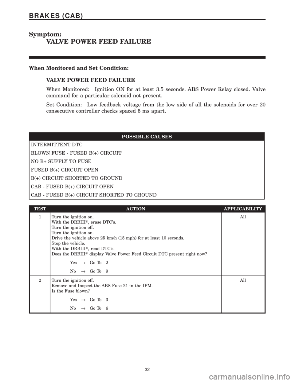
Symptom:
VALVE POWER FEED FAILURE
When Monitored and Set Condition:
VALVE POWER FEED FAILURE
When Monitored: Ignition ON for at least 3.5 seconds. ABS Power Relay closed. Valve
command for a particular solenoid not present.
Set Condition: Low feedback voltage from the low side of all the solenoids for over 20
consecutive controller checks spaced 5 ms apart.
POSSIBLE CAUSES
INTERMITTENT DTC
BLOWN FUSE - FUSED B(+) CIRCUIT
NO B+ SUPPLY TO FUSE
FUSED B(+) CIRCUIT OPEN
B(+) CIRCUIT SHORTED TO GROUND
CAB - FUSED B(+) CIRCUIT OPEN
CAB - FUSED B(+) CIRCUIT SHORTED TO GROUND
TEST ACTION APPLICABILITY
1 Turn the ignition on.
With the DRBIIIt, erase DTC's.
Turn the ignition off.
Turn the ignition on.
Drive the vehicle above 25 km/h (15 mph) for at least 10 seconds.
Stop the vehicle.
With the DRBIIIt, read DTC's.
Does the DRBIIItdisplay Valve Power Feed Circuit DTC present right now?All
Ye s®Go To 2
No®Go To 9
2 Turn the ignition off.
Remove and Inspect the ABS Fuse 21 in the IPM.
Is the Fuse blown?All
Ye s®Go To 3
No®Go To 6
32
BRAKES (CAB)
Page 1190 of 4284
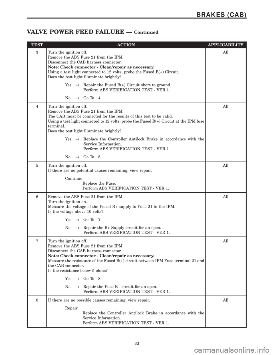
TEST ACTION APPLICABILITY
3 Turn the ignition off.
Remove the ABS Fuse 21 from the IPM.
Disconnect the CAB harness connector.
Note: Check connector - Clean/repair as necessary.
Using a test light connected to 12 volts, probe the Fused B(+) Circuit.
Does the test light illuminate brightly?All
Ye s®Repair the Fused B(+) Circuit short to ground.
Perform ABS VERIFICATION TEST - VER 1.
No®Go To 4
4 Turn the ignition off.
Remove the ABS Fuse 21 from the IPM.
The CAB must be connected for the results of this test to be valid.
Using a test light connected to 12 volts, probe the Fused B(+) Circuit at the IPM fuse
terminal.
Does the test light illuminate brightly?All
Ye s®Replace the Controller Antilock Brake in accordance with the
Service Information.
Perform ABS VERIFICATION TEST - VER 1.
No®Go To 5
5 Turn the ignition off.
If there are no potential causes remaining, view repair.All
Continue
Replace the Fuse.
Perform ABS VERIFICATION TEST - VER 1.
6 Remove the ABS Fuse 21 from the IPM.
Turn the ignition on.
Measure the voltage of the Fused B+ supply to Fuse 21 in the IPM.
Is the voltage above 10 volts?All
Ye s®Go To 7
No®Repair the B+ Supply circuit for an open.
Perform ABS VERIFICATION TEST - VER 1.
7 Turn the ignition off.
Remove the ABS Fuse 21 from the IPM.
Disconnect the CAB harness connector.
Note: Check connector - Clean/repair as necessary.
Measure the resistance of the Fused B(+) circuit between IPM Fuse terminal 21 and
the CAB connector.
Is the resistance below 5 ohms?All
Ye s®Go To 8
No®Repair the Fuse B+ circuit for an open.
Perform ABS VERIFICATION TEST - VER 1.
8 If there are no possible causes remaining, view repair. All
Repair
Replace the Controller Antilock Brake in accordance with the
Service Information.
Perform ABS VERIFICATION TEST - VER 1.
33
BRAKES (CAB)
VALVE POWER FEED FAILURE ÐContinued
Page 1192 of 4284
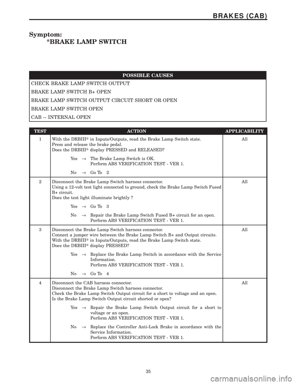
Symptom:
*BRAKE LAMP SWITCH
POSSIBLE CAUSES
CHECK BRAKE LAMP SWITCH OUTPUT
BRAKE LAMP SWITCH B+ OPEN
BRAKE LAMP SWITCH OUTPUT CIRCUIT SHORT OR OPEN
BRAKE LAMP SWITCH OPEN
CAB -- INTERNAL OPEN
TEST ACTION APPLICABILITY
1 With the DRBIIItin Inputs/Outputs, read the Brake Lamp Switch state.
Press and release the brake pedal.
Does the DRBIIItdisplay PRESSED and RELEASED?All
Ye s®The Brake Lamp Switch is OK.
Perform ABS VERIFICATION TEST - VER 1.
No®Go To 2
2 Disconnect the Brake Lamp Switch harness connector.
Using a 12-volt test light connected to ground, check the Brake Lamp Switch Fused
B+ circuit.
Does the test light illuminate brightly ?All
Ye s®Go To 3
No®Repair the Brake Lamp Switch Fused B+ circuit for an open.
Perform ABS VERIFICATION TEST - VER 1.
3 Disconnect the Brake Lamp Switch harness connector.
Connect a jumper wire between the Brake Lamp Switch B+ and Output circuits.
With the DRBIIItin Inputs/Outputs, read the Brake Lamp Switch state.
Does the DRBIIItdisplay PRESSED?All
Ye s®Replace the Brake Lamp Switch in accordance with the Service
Information.
Perform ABS VERIFICATION TEST - VER 1.
No®Go To 4
4 Disconnect the CAB harness connector.
Disconnect the Brake Lamp Switch harness connector.
Check the Brake Lamp Switch Output circuit for a short to voltage and an open.
Is the Brake Lamp Switch Output circuit shorted or open?All
Ye s®Repair the Brake Lamp Switch Output circuit for a short to
voltage or an open.
Perform ABS VERIFICATION TEST - VER 1.
No®Replace the Controller Anti-Lock Brake in accordance with the
Service Information.
Perform ABS VERIFICATION TEST - VER 1.
35
BRAKES (CAB)
Page 1199 of 4284
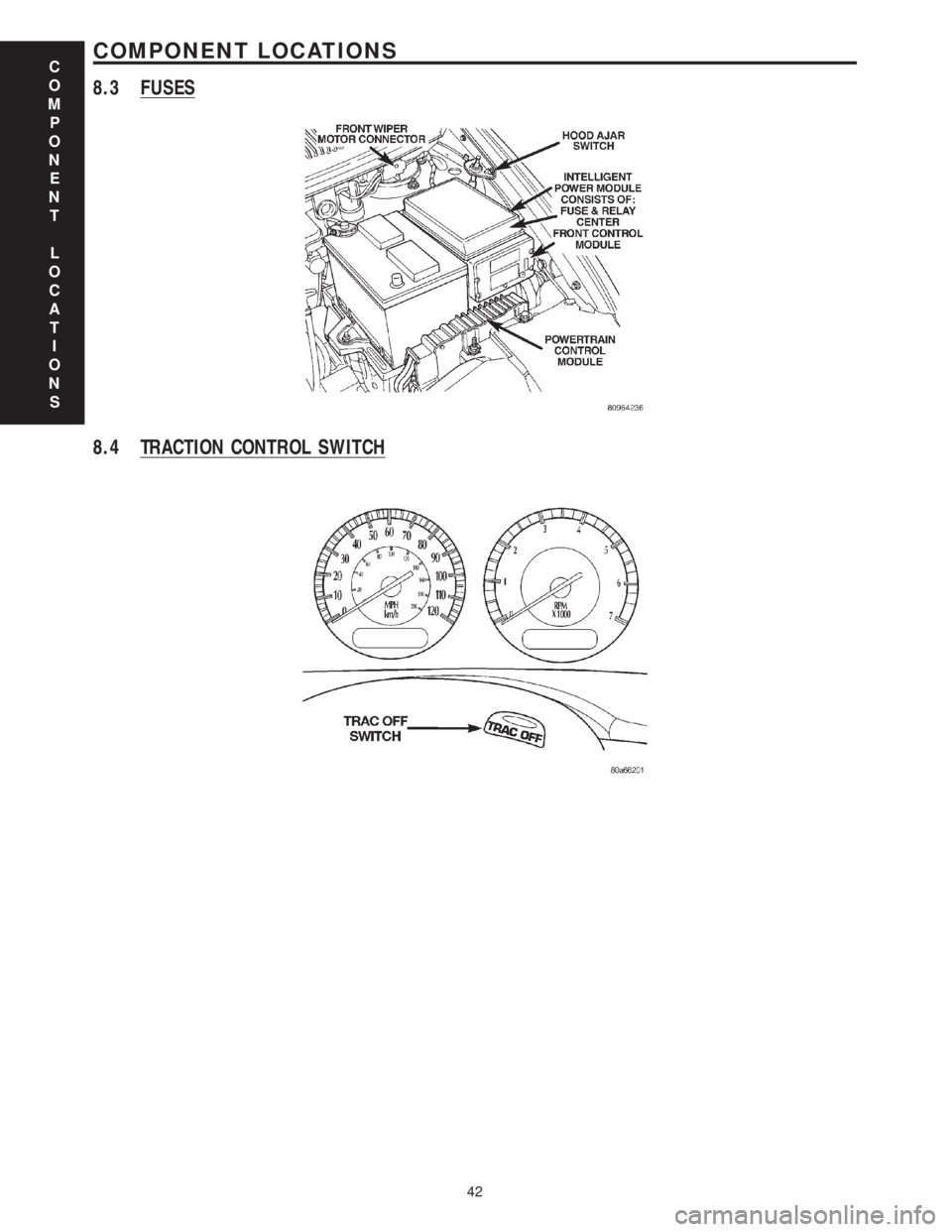
8.3 FUSES
8.4 TRACTION CONTROL SWITCH
C
O
M
P
O
N
E
N
T
L
O
C
A
T
I
O
N
S
42
COMPONENT LOCATIONS
Page 1204 of 4284

9.0 CONNECTOR PINOUTS
CONTROLLER ANTILOCK BRAKE - BLACK 24 WAYCAV CIRCUIT FUNCTION
1 Z107 12BK/DG GROUND
2 B1 18DG/OR RIGHT REAR WHEEL SPEED SENSOR 12 VOLT SUPPLY
3 B2 18DG/LB RIGHT REAR WHEEL SPEED SENSOR SIGNAL
4- -
5 D25 18WT/VT PCI BUS
6 B6 18DG/WT RIGHT FRONT WHEEL SPEED SENSOR 12 VOLT SUPPLY
7 B7 18DG/VT RIGHT FRONT WHEEL SPEED SENSOR SIGNAL
8- -
9 A111 12DG/RD FUSED B(+)
10 F500 18DG/PK FUSED IGNITION SWITCH OUTPUT
11 - -
12 - -
13 - -
14 - -
15 - -
16 Z127 12BK/DG GROUND
17 - -
18 L50 18WT/TN BRAKE LAMP SWITCH OUTPUT
19 B3 18DG/YL LEFT REAR WHEEL SPEED SENSOR 12 VOLT SUPPLY
20 B4 18DG/GY LEFT REAR WHEEL SPEED SENSOR SIGNAL
21 - -
22 B8 18DG/TN LEFT FRONT WHEEL SPEED SENSOR 12 VOLT SUPPLY
23 B9 18DG/LG LEFT FRONT WHEEL SPEED SENSOR SIGNAL
24 A107 12TN/RD FUSED B(+)
DATA LINK CONNECTOR - WHITE 16 WAYCAV CIRCUIT FUNCTION
1- -
2 D25 20WT/VT PCI BUS
3- -
4 Z11 18BK/LG GROUND
5 Z111 18BK/WT GROUND
6 D20 20WT/LG SCI RECEIVE
7 D21 20WT/BR SCI TRANSMIT
8- -
9 D23 20WT/BR FLASH PROGRAM ENABLE
10 - -
11 - -
12 - -
13 - -
14 D16 20WT/OR SCI RECEIVE
15 - -
16 A105 20DB/RD FUSED B(+)
C
O
N
N
E
C
T
O
R
P
I
N
O
U
T
S
47
CONNECTOR PINOUTS
Page 1205 of 4284

DIAGNOSTIC JUNCTION PORT - BLACK 16 WAYCAV CIRCUIT FUNCTION
1 D25 20WT/VT PCI BUS (PCM/SKIM)
2 D25 20WT/VT PCI BUS (HVAC)
3 D25 20WT/VT PCI BUS (RADIO)
4 D25 20WT/VT PCI BUS (ORC)
5 D25 20WT/VT PCI BUS (CLUSTER)
6 D25 20WT/VT PCI BUS (BCM)
7 D25 20WT/VT PCI BUS (DLC)
8 D25 20WT/VT PCI BUS (OVERHEAD CONSOLE)
9 D25 20WT/VT PCI BUS (IPM)
10 D25 20WT/VT PCI BUS (LSIACM)
11 D25 20WT/VT PCI BUS (MEMORY SEAT/MIRROR)
12 D25 20WT/VT PCI BUS (PWR DOOR/ LT, RT LIFTGATE)
13 D25 20WT/VT PCI BUS (RSIACM)
14 - -
15 - -
16 - -
INTELLIGENT POWER MODULE C4 - GRAY 10 WAYCAV CIRCUIT FUNCTION
1 Z127 12BK/DG GROUND
2 T750 12YL/GY ENGINE STARTER MOTOR RELAY OUTPUT
3 K342 16BR/WT AUTOMATIC SHUTDOWN RELAY OUTPUT
4 F500 18DG/PK (ANTILOCK
BRAKES)FUSED IGNITION SWITCH RELAY OUTPUT (RUN)
5- -
6 D25 16WT/VT (ANTILOCK
BRAKES)PCI BUS
7 A107 12TN/RD (ANTILOCK
BRAKES)FUSED B(+)
8 A111 12DG/RD (ANTILOCK
BRAKES)FUSED B(+)
9 A701 14BR/RD FUSED B(+)
10 - -
LEFT FRONT WHEEL SPEED SENSOR - BLACK 2 WAYCAV CIRCUIT FUNCTION
1 B9 18DG/LG LEFT FRONT WHEEL SPEED SENSOR SIGNAL
2 B8 18DG/TN LEFT FRONT WHEEL SPEED SENSOR 12 VOLT SUPPLY
C
O
N
N
E
C
T
O
R
P
I
N
O
U
T
S
48
CONNECTOR PINOUTS
Page 1208 of 4284
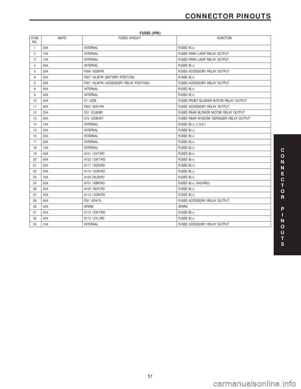
FUSES (IPM)FUSE
NO.AMPS FUSED CIRCUIT FUNCTION
1 20A INTERNAL FUSED B(+)
2 15A INTERNAL FUSED PARK LAMP RELAY OUTPUT
3 15A INTERNAL FUSED PARK LAMP RELAY OUTPUT
4 30A INTERNAL FUSED B(+)
5 20A F306 16DB/PK FUSED ACCESSORY RELAY OUTPUT
6 20A F307 16LB/PK (BATTERY POSITION) FUSED B(+)
6 20A F307 16LB/PK (ACCESSORY RELAY POSITION) FUSED ACCESSORY RELAY OUTPUT
8 20A INTERNAL FUSED B(+)
9 40A INTERNAL FUSED B(+)
10 40A C7 12DB FUSED FRONT BLOWER MOTOR RELAY OUTPUT
11 20A F302 18GY/PK FUSED ACCESSORY RELAY OUTPUT
12 25A C51 12LB/BR FUSED REAR BLOWER MOTOR RELAY OUTPUT
13 40A C15 12DB/WT FUSED REAR WINDOW DEFOGGER RELAY OUTPUT
14 15A INTERNAL FUSED B(+) (I.O.D.)
15 20A INTERNAL FUSED B(+)
16 25A INTERNAL FUSED B(+)
17 20A INTERNAL FUSED B(+)
18 15A INTERNAL FUSED B(+)
19 40A A101 12VT/RD FUSED B(+)
20 40A A102 12WT/RD FUSED B(+)
21 25A A111 12DG/RD FUSED B(+)
22 40A A110 12OR/RD FUSED B(+)
23 10A A106 20LB/RD FUSED B(+)
24 20A A701 16BR/RD FUSED B(+) (HAZARD)
26 20A A103 18GY/RD FUSED B(+)
27 40A A112 12OR/RD FUSED B(+)
28 40A F30 12PK/YL FUSED ACCESSORY RELAY OUTPUT
30 40A SPARE SPARE
31 40A A113 12WT/RD FUSED B(+)
32 40A A115 12YL/RD FUSED B(+)
33 15A INTERNAL FUSED ACCESSORY RELAY OUTPUT
C
O
N
N
E
C
T
O
R
P
I
N
O
U
T
S
51
CONNECTOR PINOUTS
Page 1226 of 4284

4.0 DISCLAIMERS, SAFETY,
WARNINGS
4.1 DISCLAIMERS
All information, illustrations, and specifications
contained in this manual are based on the latest
information available at the time of publication.
The right is reserved to make changes at any time
without notice.
4.2 SAFETY
4.2.1 TECHNICIAN SAFETY INFORMATION
WARNING: ENGINES PRODUCE CARBON
MONOXIDE THAT IS ODORLESS, CAUSES
SLOWER REACTION TIME, AND CAN LEAD
TO SERIOUS INJURY. WHEN THE ENGINE IS
OPERATING, KEEP SERVICE AREAS WELL
VENTILATED OR ATTACH THE VEHICLE
EXHAUST SYSTEM TO THE SHOP EXHAUST
REMOVAL SYSTEM.
Set the parking brake and block the wheels before
testing or repairing the vehicle. It is especially
important to block the wheels on front wheel drive
vehicles; the parking brake does not hold the drive
wheels.
When servicing a vehicle, always wear eye pro-
tection, and remove any metal jewelry such as
watchbands or bracelets that might make electrical
contact.
When diagnosing a powertrain system problem,
it is important to follow approved procedures where
applicable. These procedures can be found in the
service manual. Following these procedures is very
important to the safety of individuals performing
diagnostic tests.
4.2.2 VEHICLE PREPARATION FOR
TESTING
Make sure the vehicle being tested has a fully
charged battery. If it does not, false diagnostic codes
or error messages may occur.
4.2.3 SERVICING SUB-ASSEMBLIES
Some components of the powertrain system are
intended to be serviced as an assembly only. At-
tempting to remove or repair certain system sub-
components may result in personal injury and/or
improper system operation. Only those components
with approved repair and installation procedures in
the service manual should be serviced.
4.2.4 DRBIIITSAFETY INFORMATION
WARNING: EXCEEDING THE LIMITS OF THE
DRBIIITMULTIMETER IS DANGEROUS. IT
CAN EXPOSE YOU TO SERIOUS OR
POSSIBLY FATAL INJURY. CAREFULLY
READ AND UNDERSTAND THE CAUTIONS
AND SPECIFICATION LIMITS.
Follow the vehicle manufacturer 's service specifi-
cations at all times.
²Do not use the DRBIIItif it has been damaged.
²Do not use the test leads if the insulation is
damaged or if metal is exposed.
²To avoid electrical shock, do not touch the test
leads, tip or the circuit being tested.
²Choose the proper range and function for the
measurement. Do not try voltage or current mea-
surements that may exceed the rated capacity.
²Do not exceed the limits shown in the table below:
FUNCTION INPUT LIMIT
Volts 0-500 peak volts AC
0-500 volts DC
Ohms (Resistance)* 0-1.12 megohms
Frequency Measure
Frequency Generated0-10 kHz
Temperature -58 - +1100ÉF
-50 - +600ÉC
* Ohms cannot be measured if voltage is present.
Ohms can be measured only in a non-powered
circuit.
²Voltage between any terminal and ground must
not exceed 500v DC or 500v peak AC.
²Use caution when measuring voltage above 25v
DC or 25v AC.
²The circuit being tested must be protected by a 10
amp fuse or circuit breaker.
²Use the low current shunt to measure circuits up
to 10 amps. Use the high current shunt to mea-
sure circuits exceeding 10 amps.
²When testing for the presence of voltage or cur-
rent, make sure the meter is functioning cor-
rectly. Take a reading of a known voltage or
current before accepting a zero reading.
²When measuring current, connect the meter in
series with the load.
²Disconnect the live test lead before disconnecting
the common test lead.
7
GENERAL INFORMATION