fuse CHRYSLER VOYAGER 2001 Service Manual
[x] Cancel search | Manufacturer: CHRYSLER, Model Year: 2001, Model line: VOYAGER, Model: CHRYSLER VOYAGER 2001Pages: 4284, PDF Size: 83.53 MB
Page 1227 of 4284

4.3 WARNINGS AND CAUTIONS
4.3.1 ROAD TEST WARNINGS
Some complaints will require a test drive as part
of the repair verification procedure. The purpose of
the test drive is to try to duplicate the diagnostic
code or symptom condition.
CAUTION: BEFORE ROAD TESTING A
VEHICLE, BE SURE THAT ALL
COMPONENTS ARE REASSEMBLED. DUR-
ING THE TEST DRIVE, DO NOT HANG THE
DRBIIITFROM THE REAR VIEW MIRROR. DO
NOT ATTEMPT TO READ THE DRBIIITWHILE
DRIVING. HAVE AN ASSISTANT AVAILABLE
TO OPERATE THE DRBIIIT.
4.3.2 VEHICLE DAMAGE CAUTIONS
Before disconnecting any control module, make
sure the ignition is off. Failure to do so could
damage the module. When testing voltage or circuit
integrity at any control module, use the terminal
side (not the wire end) of the harness connector. Do
not probe through the insulation; this will damage
it and eventually cause it to fail because of corro-
sion.
Be careful when performing electrical test so as to
prevent accidental shorting of terminals. Such a
mistake can damage fuses or components. Also, a
second code could be set, making diagnosis of the
original problem more difficult.
5.0 REQUIRED TOOLS AND
EQUIPMENT
DRBIIIt(diagnostic read-out box) scan tool
vacuum gauge
ammeter
ohmmeter
jumper wires and probes
oscilloscope
6.0 GLOSSARY OF TERMS
A/Cair conditioning
APPaccelerator pedal position (sensor)
backfire,
popbackfuel ignites in either the intake or
the exhaust system
BCMbody control module
BPboost pressure (sensor)CKPcrankshaft position (sensor)
CMPcamshaft position (sensor)
cuts out,
missesa steady pulsation or the inability of
the engine to maintain a consistent
rpm
DLCdata link connector
detona-
tion,
spark
knocka mild to severe ping, especially un-
der loaded engine conditions
ECMengine control module
ECTengine coolant temperature (sensor)
EGRexhaust gas recirculation
(solenoid/valve)
hard
startthe engine takes longer than usual
to start, even though it is able to
crank at normal speed.
IATintake air temperature (sensor)
IPMintelligent power module
lack of
power,
sluggishthe engine power output has been
reduced
MAFmass air flow (sensor)
MILmalfunction indicator lamp
msmillisecond(s)
PDCpower distribution center
poor fuel
economythere is significantly less fuel mile-
age than other vehicles of the same
design and configuration
runs
rough/
unstable
idlethe engine runs unevenly at idle
causing the engine to shake if it is
severe enough
S/Cspeed control
SKIMsentry key immobilizer module
SKISsentry key immobilizer system
start and
stallThe engine starts but immediately
dies (stalls)
surgeengine rpm fluctuation without cor-
responding change in accelerator
pedal position
SRCsignal range check
WIFwater in fuel (sensor)
VSSvehicle speed sensor
8
GENERAL INFORMATION
Page 1339 of 4284

Symptom List:
P0560-SYSTEM VOLTAGE TOO LOW
*CHECKING THE CHARGING SYSTEM OPERATION - DIESEL
Test Note: All symptoms listed above are diagnosed using the same tests.
The title for the tests will be P0560-SYSTEM VOLTAGE TOO
LOW.
When Monitored and Set Condition:
P0560-SYSTEM VOLTAGE TOO LOW
When Monitored: With the engine running.
Set Condition: The ECM detects the system voltage at least 0.5 volt below the target
charging voltage for at least 3 seconds.
POSSIBLE CAUSES
CHECK FOR CYCLING VOLTAGE ON THE GENERATOR FIELD DRIVER CIRCUIT
INTERMITTENT CONDITION
GENERATOR BELT CONDITION OR TENSION
HIGH RESISTANCE IN THE FUEL HEATER RELAY OUTPUT CIRCUIT TO THE ECM
GENERATOR FIELD DRIVER CIRCUIT SHORTED TO VOLTAGE
GENERATOR FUSED B+ CIRCUIT HIGH RESISTANCE
ECM/PCM RELAY OUTPUT CIRCUIT OPEN
GENERATOR GROUND CIRCUIT HIGH RESISTANCE
GENERATOR FIELD DRIVER CIRCUIT OPEN
ENGINE CONTROL MODULE
TEST ACTION APPLICABILITY
1NOTE: If there are any Battery Sense DTCs (P1511 or P1512) present with
this DTC, diagnose the Battery Sense DTCs first.
NOTE: Inspect the vehicle for aftermarket accessories that may exceed the
Generator capacity.
NOTE: The battery must be fully charged before continuing.
Inspect the generator belt condition and tension.
Is the generator belt in good condition and tensioned properly?All
Ye s®Go To 2
No®Repair as necessary.
Perform CHARGING VERIFICATION - VER-3.
120
DRIVEABILITY - DIESEL
Page 1340 of 4284

TEST ACTION APPLICABILITY
2 Turn the ignition on.
With the DRB, actuate the Generator Field.
Measure the voltage between ground and the Generator Field Driver circuit by back
probing the Generator Field harness connector with a voltmeter.
NOTE: The voltage should cycle from Battery voltage to below 2.0 volts
every 1.4 seconds.
While monitoring the voltmeter, wiggle the generator field harness and connectors
between the generator, ECM and the ECM/PCM Relay (in the PDC).
Was there any interruption of the normal voltage cycling?All
Ye s®Repair the harness as necessary where the wiggling caused the
interruption.
Perform CHARGING VERIFICATION - VER-3.
No®Go To 3
NOTE: With the DRB, stop the Generator Field actuation.
3 Connect the positive lead of a voltmeter to the generator B+ (12V) terminal and the
negative lead to the battery positive (+) post.
WARNING: WHEN THE ENGINE IS OPERATING, DO NOT STAND IN A
DIRECT LINE WITH THE FAN. DO NOT PUT YOUR HANDS NEAR THE
PULLEYS, BELTS OR FAN. DO NOT WEAR LOOSE CLOTHING.
Start the engine.
Is the voltage on the voltmeter below 0.4 volt?All
Ye s®Go To 4
No®Repair the Generator Fused B+ circuit for high resistance.
Perform CHARGING VERIFICATION - VER-3.
4 Connect the positive lead of a voltmeter to the generator case (housing) and the
negative lead to the battery negative (-) post.
WARNING: WHEN THE ENGINE IS OPERATING, DO NOT STAND IN A
DIRECT LINE WITH THE FAN. DO NOT PUT YOUR HANDS NEAR THE
PULLEYS, BELTS OR FAN. DO NOT WEAR LOOSE CLOTHING.
Start the engine.
Is the voltage on the voltmeter below 0.4 volt?All
Ye s®Go To 5
No®Repair the Generator Ground circuit for high resistance.
Perform CHARGING VERIFICATION - VER-3.
5 Turn the ignition off, then on.
With the DRB, read and record the Battery Voltage.
With a voltmeter, measure and record the voltage between the Battery terminals.
Compare the DRB Battery Voltage reading to the voltmeter reading.
Is the difference between the two readings less than 0.5 volt?All
Ye s®Go To 6
No®Go To 7
121
DRIVEABILITY - DIESEL
P0560-SYSTEM VOLTAGE TOO LOW ÐContinued
Page 1358 of 4284
Symptom:
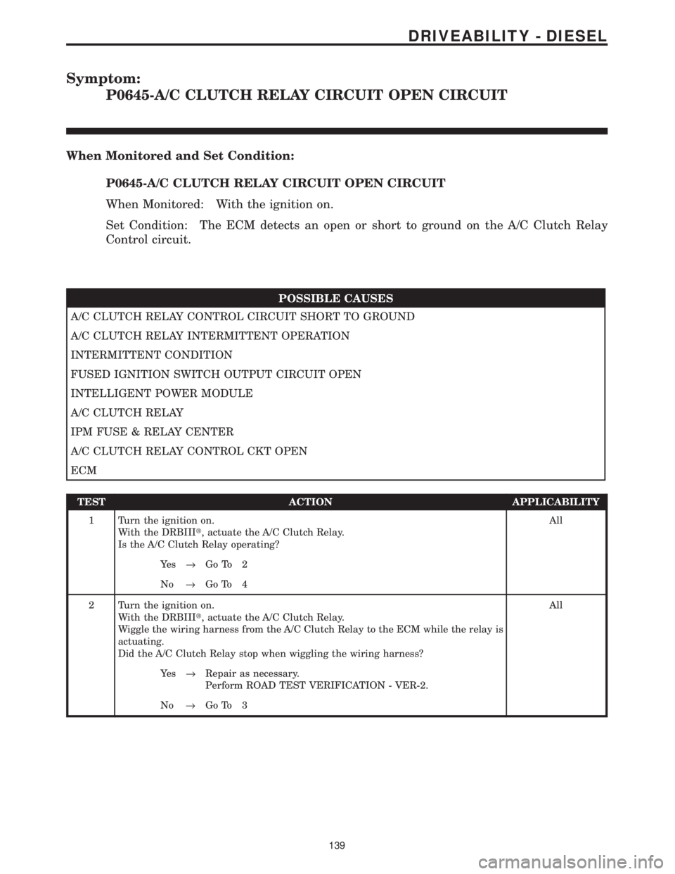
P0645-A/C CLUTCH RELAY CIRCUIT OPEN CIRCUIT
When Monitored and Set Condition:
P0645-A/C CLUTCH RELAY CIRCUIT OPEN CIRCUIT
When Monitored: With the ignition on.
Set Condition: The ECM detects an open or short to ground on the A/C Clutch Relay
Control circuit.
POSSIBLE CAUSES
A/C CLUTCH RELAY CONTROL CIRCUIT SHORT TO GROUND
A/C CLUTCH RELAY INTERMITTENT OPERATION
INTERMITTENT CONDITION
FUSED IGNITION SWITCH OUTPUT CIRCUIT OPEN
INTELLIGENT POWER MODULE
A/C CLUTCH RELAY
IPM FUSE & RELAY CENTER
A/C CLUTCH RELAY CONTROL CKT OPEN
ECM
TEST ACTION APPLICABILITY
1 Turn the ignition on.
With the DRBIIIt, actuate the A/C Clutch Relay.
Is the A/C Clutch Relay operating?All
Ye s®Go To 2
No®Go To 4
2 Turn the ignition on.
With the DRBIIIt, actuate the A/C Clutch Relay.
Wiggle the wiring harness from the A/C Clutch Relay to the ECM while the relay is
actuating.
Did the A/C Clutch Relay stop when wiggling the wiring harness?All
Ye s®Repair as necessary.
Perform ROAD TEST VERIFICATION - VER-2.
No®Go To 3
139
DRIVEABILITY - DIESEL
Page 1359 of 4284

TEST ACTION APPLICABILITY
3WARNING: KEEP CLEAR OF THE ENGINE'S MOVING PARTS.
NOTE: The conditions that set the DTC are not present at this time. The
following list may help in identifying the intermittent condition.
With the engine running at normal operating temperature, monitor the DRB
parameters related to the DTC while wiggling the wiring harness. Look for param-
eter values to change and/or a DTC to set.
Review the DRB Freeze Frame information. If possible, try to duplicate the
conditions under which the DTC was set.
Refer to any Technical Service Bulletins (TSB) that may apply.
Visually inspect the related wiring harness. Look for any chafed, pierced, pinched, or
partially broken wires.
Visually inspect the related wiring harness connectors. Look for broken, bent, pushed
out, or corroded terminals.
Were any of the above conditions present?All
Ye s®Repair as necessary.
Perform ROAD TEST VERIFICATION - VER-2.
No®Test Complete.
4 Turn the ignition off.
Remove the A/C Clutch Relay from the IPM.
Turn the ignition on.
Using a 12-volt test light connected to ground, probe the Fused Ignition Switch
circuit in the IPM.
Does the test light illuminate?All
Ye s®Go To 5
No®Go To 10
5 Turn the ignition off.
Remove the A/C Clutch Relay from the IPM.
Turn the ignition on.
Using a 12-volt test light connected to 12-volts, probe the A/C Clutch Relay Control
circuit in the IPM.
With the DRBIIIt, actuate the A/C Clutch Relay.
Does the test light cycle on and off?All
Ye s®Replace the A/C Clutch Relay.
Perform ROAD TEST VERIFICATION - VER-2.
No®Go To 6
6 Turn the ignition off.
Disconnect the Intelligent Power Module C3 harness connector.
Turn the ignition on.
Using a 12-volt test light connected to 12-volts, probe the A/C Clutch Relay Control
circuit in the IPM harness connector.
With the DRBIIIt, actuate the A/C Clutch Relay.
Does the test light flash on and off?All
Ye s®Replace the IPM Fused & Relay Center.
Perform ROAD TEST VERIFICATION - VER-2.
No®Go To 7
140
DRIVEABILITY - DIESEL
P0645-A/C CLUTCH RELAY CIRCUIT OPEN CIRCUIT ÐContinued
Page 1360 of 4284

TEST ACTION APPLICABILITY
7 Turn the ignition off.
Disconnect the Intelligent Power Module C3 harness connector.
Disconnect the ECM harness connector.
Measure the resistance of the A/C Clutch Relay Control circuit between the
Intelligent Power Module C3 harness connector and the ECM harness connector.
Is the resistance below 5.0 ohms.All
Ye s®Go To 8
No®Repair the A/C Clutch Relay Control circuit for an open.
Perform ROAD TEST VERIFICATION - VER-2.
8 Turn the ignition off.
Disconnect the Intelligent Power Module C3 harness connector.
Disconnect the ECM harness connector.
Measure the resistance of the A/C Clutch Relay Control circuit in the Intelligent
Power Module C3 harness connector to ground.
Is the resistance below 5.0 ohms.All
Ye s®Repair the A/C Clutch Relay Control circuit for a short to ground.
Perform ROAD TEST VERIFICATION - VER-2.
No®Go To 9
9 If there are no possible causes remaining, view repair. All
Repair
Replace and program the Engine Control Module in accordance
with the Service Information.
Perform ROAD TEST VERIFICATION - VER-2.
10 Turn the ignition off.
Disconnect the Intelligent Power Module C3 harness connector.
Turn the ignition on.
Using a 12-volt test light connected to ground, probe the Fused Ignition Switch
circuit in the IPM harness connector.
Does the test light illuminate?All
Ye s®Replace the IPM Fuse & Relay Center.
Perform ROAD TEST VERIFICATION - VER-2.
No®Repair the Fused Ignition Switch Output circuit for an open.
Perform ROAD TEST VERIFICATION - VER-2.
141
DRIVEABILITY - DIESEL
P0645-A/C CLUTCH RELAY CIRCUIT OPEN CIRCUIT ÐContinued
Page 1361 of 4284
Symptom:
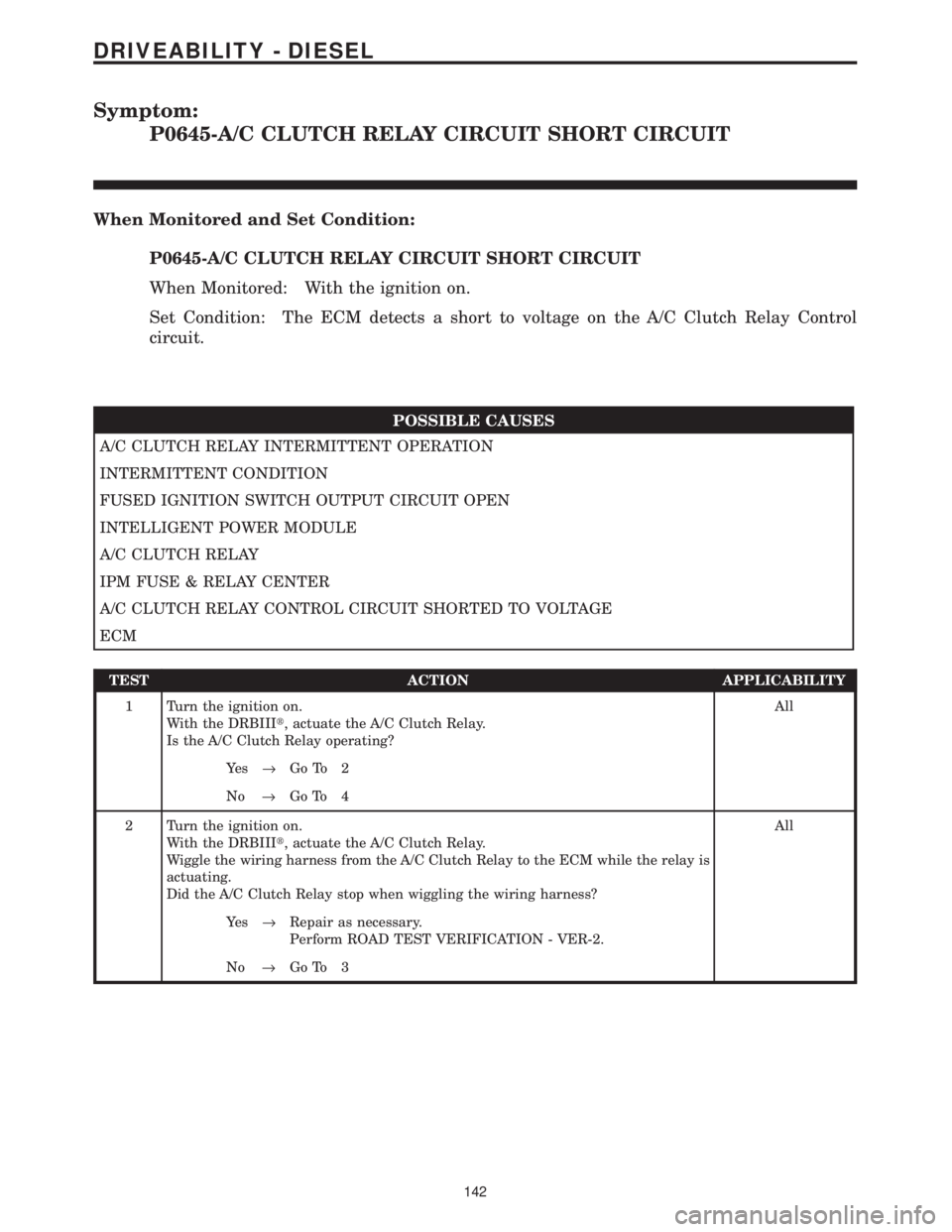
P0645-A/C CLUTCH RELAY CIRCUIT SHORT CIRCUIT
When Monitored and Set Condition:
P0645-A/C CLUTCH RELAY CIRCUIT SHORT CIRCUIT
When Monitored: With the ignition on.
Set Condition: The ECM detects a short to voltage on the A/C Clutch Relay Control
circuit.
POSSIBLE CAUSES
A/C CLUTCH RELAY INTERMITTENT OPERATION
INTERMITTENT CONDITION
FUSED IGNITION SWITCH OUTPUT CIRCUIT OPEN
INTELLIGENT POWER MODULE
A/C CLUTCH RELAY
IPM FUSE & RELAY CENTER
A/C CLUTCH RELAY CONTROL CIRCUIT SHORTED TO VOLTAGE
ECM
TEST ACTION APPLICABILITY
1 Turn the ignition on.
With the DRBIIIt, actuate the A/C Clutch Relay.
Is the A/C Clutch Relay operating?All
Ye s®Go To 2
No®Go To 4
2 Turn the ignition on.
With the DRBIIIt, actuate the A/C Clutch Relay.
Wiggle the wiring harness from the A/C Clutch Relay to the ECM while the relay is
actuating.
Did the A/C Clutch Relay stop when wiggling the wiring harness?All
Ye s®Repair as necessary.
Perform ROAD TEST VERIFICATION - VER-2.
No®Go To 3
142
DRIVEABILITY - DIESEL
Page 1362 of 4284

TEST ACTION APPLICABILITY
3WARNING: KEEP CLEAR OF THE ENGINE'S MOVING PARTS.
NOTE: The conditions that set the DTC are not present at this time. The
following list may help in identifying the intermittent condition.
With the engine running at normal operating temperature, monitor the DRB
parameters related to the DTC while wiggling the wiring harness. Look for param-
eter values to change and/or a DTC to set.
Review the DRB Freeze Frame information. If possible, try to duplicate the
conditions under which the DTC was set.
Refer to any Technical Service Bulletins (TSB) that may apply.
Visually inspect the related wiring harness. Look for any chafed, pierced, pinched, or
partially broken wires.
Visually inspect the related wiring harness connectors. Look for broken, bent, pushed
out, or corroded terminals.
Were any of the above conditions present?All
Ye s®Repair as necessary.
Perform ROAD TEST VERIFICATION - VER-2.
No®Test Complete.
4 Turn the ignition off.
Remove the A/C Clutch Relay from the IPM.
Turn the ignition on.
Using a 12-volt test light connected to ground, probe the Fused Ignition Switch
circuit in the IPM.
Does the test light illuminate?All
Ye s®Go To 5
No®Go To 9
5 Turn the ignition off.
Remove the A/C Clutch Relay from the IPM.
Turn the ignition on.
Using a 12-volt test light connected to 12-volts, probe the A/C Clutch Relay Control
circuit in the IPM.
With the DRBIIIt, actuate the A/C Clutch Relay.
Does the test light cycle on and off?All
Ye s®Replace the A/C Clutch Relay.
Perform ROAD TEST VERIFICATION - VER-2.
No®Go To 6
6 Turn the ignition off.
Disconnect the Intelligent Power Module C3 harness connector.
Turn the ignition on.
Using a 12-volt test light connected to 12-volts, probe the A/C Clutch Relay Control
circuit in the IPM harness connector.
With the DRBIIIt, actuate the A/C Clutch Relay.
Does the test light flash on and off?All
Ye s®Replace the IPM Fused & Relay Center.
Perform ROAD TEST VERIFICATION - VER-2.
No®Go To 7
143
DRIVEABILITY - DIESEL
P0645-A/C CLUTCH RELAY CIRCUIT SHORT CIRCUIT ÐContinued
Page 1363 of 4284

TEST ACTION APPLICABILITY
7 Turn the ignition off.
Disconnect the Intelligent Power Module C3 harness connector.
Disconnect the ECM harness connector.
Remove the ECM/PCM Relay from the IPM.
Connect a jumper wire between cavity 30 and cavity 87 of the ECM/PCM Relay
connector.
Turn the ignition on.
Measure the voltage of the A/C Clutch Relay Control circuit.
Is the voltage above 1.0 volt?All
Ye s®Repair the A/C Clutch Relay Control circuit for a short to voltage.
Perform ROAD TEST VERIFICATION - VER-2.
No®Go To 8
8 If there are no possible causes remaining, view repair. All
Repair
Replace and program the Engine Control Module in accordance
with the Service Information.
Perform ROAD TEST VERIFICATION - VER-2.
9 Turn the ignition off.
Disconnect the Intelligent Power Module C3 harness connector.
Turn the ignition on.
Using a 12-volt test light connected to ground, probe the Fused Ignition Switch
circuit in the IPM harness connector.
Does the test light illuminate?All
Ye s®Replace the IPM Fuse & Relay Center.
Perform ROAD TEST VERIFICATION - VER-2.
No®Repair the Fused Ignition Switch Output circuit for an open.
Perform ROAD TEST VERIFICATION - VER-2.
144
DRIVEABILITY - DIESEL
P0645-A/C CLUTCH RELAY CIRCUIT SHORT CIRCUIT ÐContinued
Page 1368 of 4284
Symptom List:
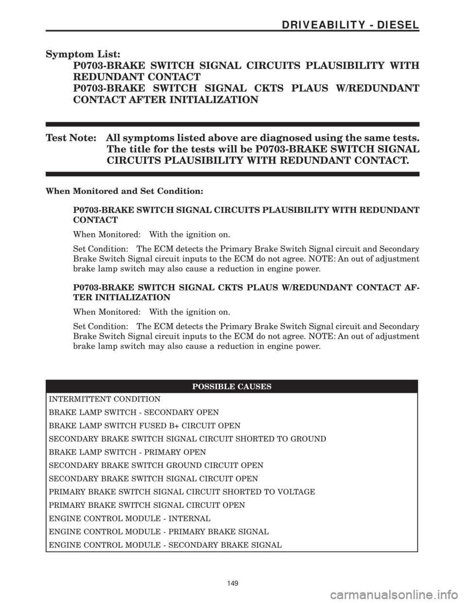
P0703-BRAKE SWITCH SIGNAL CIRCUITS PLAUSIBILITY WITH
REDUNDANT CONTACT
P0703-BRAKE SWITCH SIGNAL CKTS PLAUS W/REDUNDANT
CONTACT AFTER INITIALIZATION
Test Note: All symptoms listed above are diagnosed using the same tests.
The title for the tests will be P0703-BRAKE SWITCH SIGNAL
CIRCUITS PLAUSIBILITY WITH REDUNDANT CONTACT.
When Monitored and Set Condition:
P0703-BRAKE SWITCH SIGNAL CIRCUITS PLAUSIBILITY WITH REDUNDANT
CONTACT
When Monitored: With the ignition on.
Set Condition: The ECM detects the Primary Brake Switch Signal circuit and Secondary
Brake Switch Signal circuit inputs to the ECM do not agree. NOTE: An out of adjustment
brake lamp switch may also cause a reduction in engine power.
P0703-BRAKE SWITCH SIGNAL CKTS PLAUS W/REDUNDANT CONTACT AF-
TER INITIALIZATION
When Monitored: With the ignition on.
Set Condition: The ECM detects the Primary Brake Switch Signal circuit and Secondary
Brake Switch Signal circuit inputs to the ECM do not agree. NOTE: An out of adjustment
brake lamp switch may also cause a reduction in engine power.
POSSIBLE CAUSES
INTERMITTENT CONDITION
BRAKE LAMP SWITCH - SECONDARY OPEN
BRAKE LAMP SWITCH FUSED B+ CIRCUIT OPEN
SECONDARY BRAKE SWITCH SIGNAL CIRCUIT SHORTED TO GROUND
BRAKE LAMP SWITCH - PRIMARY OPEN
SECONDARY BRAKE SWITCH GROUND CIRCUIT OPEN
SECONDARY BRAKE SWITCH SIGNAL CIRCUIT OPEN
PRIMARY BRAKE SWITCH SIGNAL CIRCUIT SHORTED TO VOLTAGE
PRIMARY BRAKE SWITCH SIGNAL CIRCUIT OPEN
ENGINE CONTROL MODULE - INTERNAL
ENGINE CONTROL MODULE - PRIMARY BRAKE SIGNAL
ENGINE CONTROL MODULE - SECONDARY BRAKE SIGNAL
149
DRIVEABILITY - DIESEL