CHRYSLER VOYAGER 2001 Service Manual
Manufacturer: CHRYSLER, Model Year: 2001, Model line: VOYAGER, Model: CHRYSLER VOYAGER 2001Pages: 4284, PDF Size: 83.53 MB
Page 261 of 4284
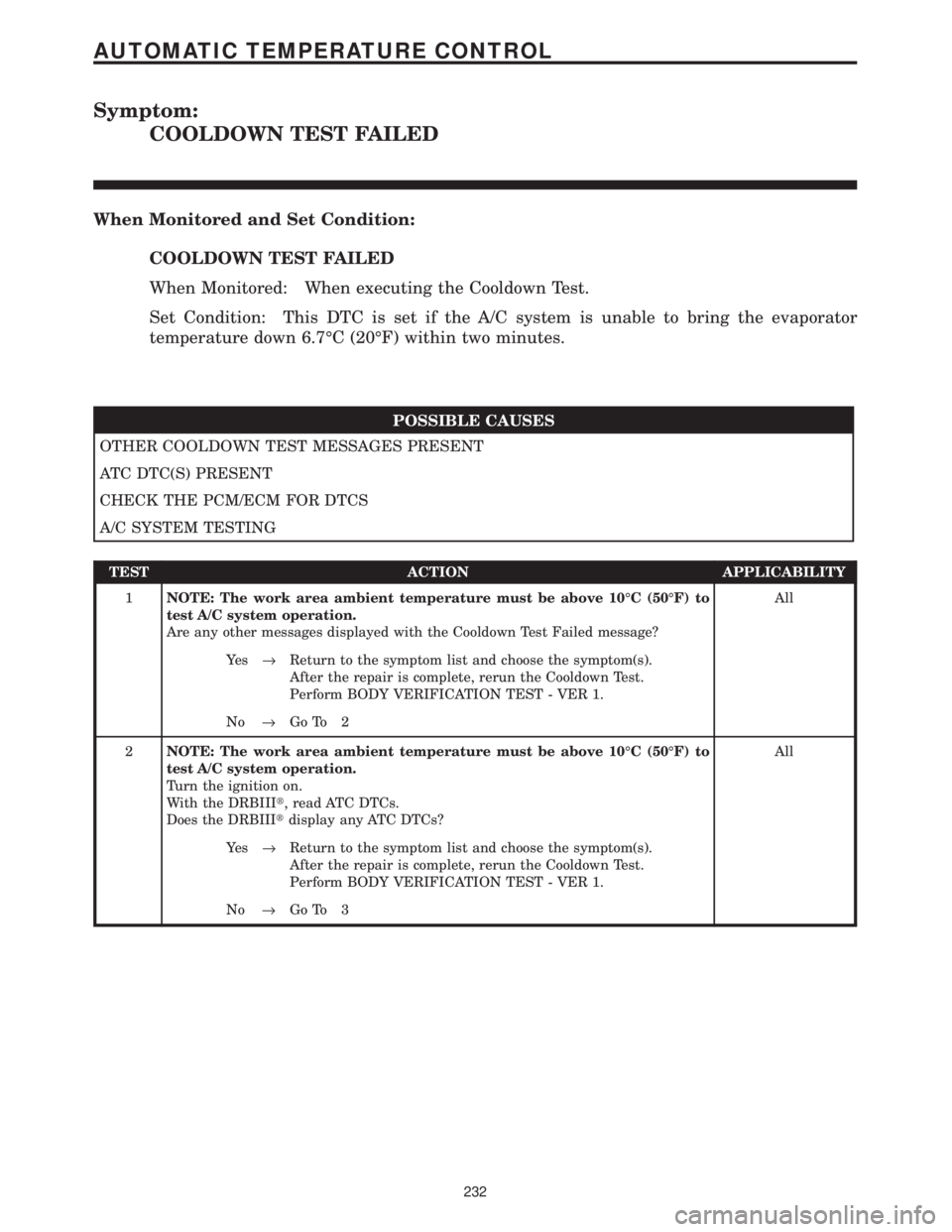
Symptom:
COOLDOWN TEST FAILED
When Monitored and Set Condition:
COOLDOWN TEST FAILED
When Monitored: When executing the Cooldown Test.
Set Condition: This DTC is set if the A/C system is unable to bring the evaporator
temperature down 6.7ÉC (20ÉF) within two minutes.
POSSIBLE CAUSES
OTHER COOLDOWN TEST MESSAGES PRESENT
ATC DTC(S) PRESENT
CHECK THE PCM/ECM FOR DTCS
A/C SYSTEM TESTING
TEST ACTION APPLICABILITY
1NOTE: The work area ambient temperature must be above 10ÉC (50ÉF) to
test A/C system operation.
Are any other messages displayed with the Cooldown Test Failed message?All
Ye s®Return to the symptom list and choose the symptom(s).
After the repair is complete, rerun the Cooldown Test.
Perform BODY VERIFICATION TEST - VER 1.
No®Go To 2
2NOTE: The work area ambient temperature must be above 10ÉC (50ÉF) to
test A/C system operation.
Turn the ignition on.
With the DRBIIIt, read ATC DTCs.
Does the DRBIIItdisplay any ATC DTCs?All
Ye s®Return to the symptom list and choose the symptom(s).
After the repair is complete, rerun the Cooldown Test.
Perform BODY VERIFICATION TEST - VER 1.
No®Go To 3
232
AUTOMATIC TEMPERATURE CONTROL
Page 262 of 4284
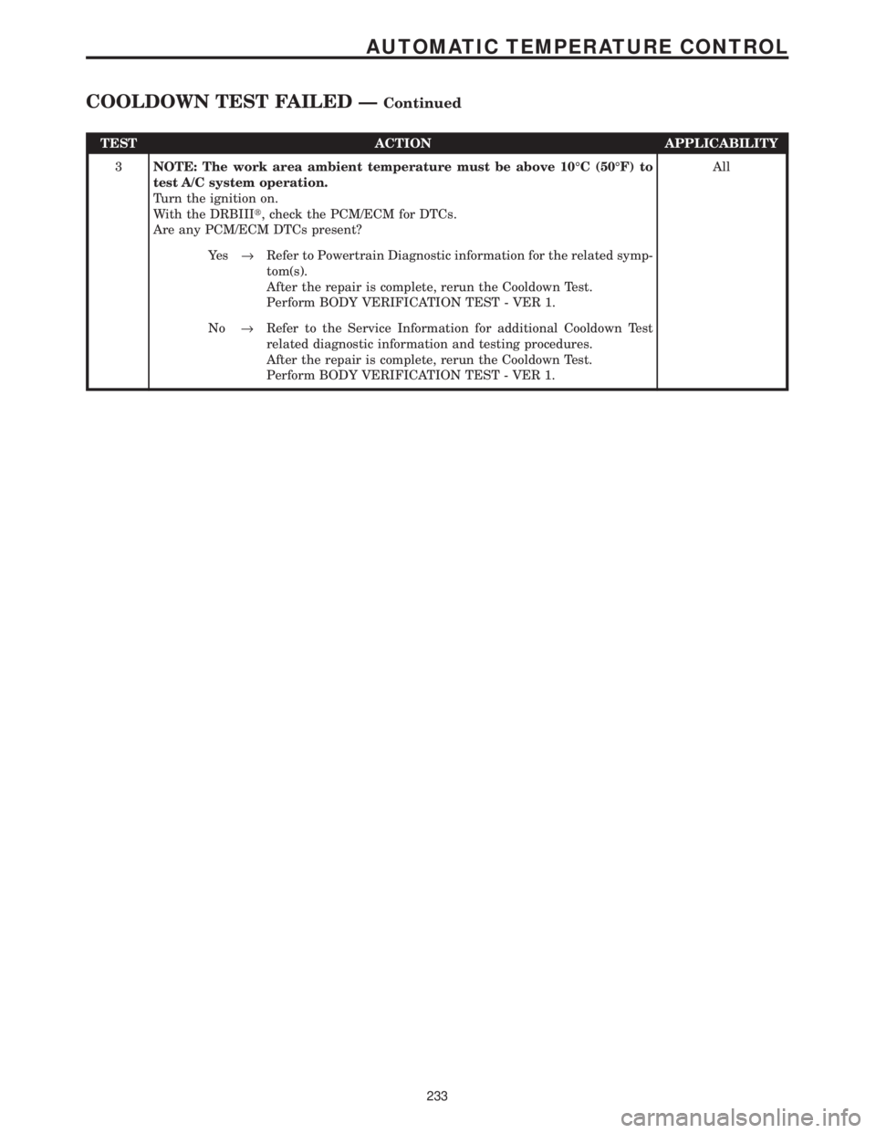
TEST ACTION APPLICABILITY
3NOTE: The work area ambient temperature must be above 10ÉC (50ÉF) to
test A/C system operation.
Turn the ignition on.
With the DRBIIIt, check the PCM/ECM for DTCs.
Are any PCM/ECM DTCs present?All
Ye s®Refer to Powertrain Diagnostic information for the related symp-
tom(s).
After the repair is complete, rerun the Cooldown Test.
Perform BODY VERIFICATION TEST - VER 1.
No®Refer to the Service Information for additional Cooldown Test
related diagnostic information and testing procedures.
After the repair is complete, rerun the Cooldown Test.
Perform BODY VERIFICATION TEST - VER 1.
233
AUTOMATIC TEMPERATURE CONTROL
COOLDOWN TEST FAILED ÐContinued
Page 263 of 4284
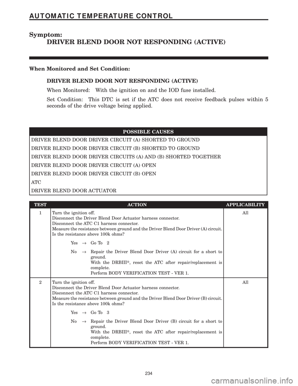
Symptom:
DRIVER BLEND DOOR NOT RESPONDING (ACTIVE)
When Monitored and Set Condition:
DRIVER BLEND DOOR NOT RESPONDING (ACTIVE)
When Monitored: With the ignition on and the IOD fuse installed.
Set Condition: This DTC is set if the ATC does not receive feedback pulses within 5
seconds of the drive voltage being applied.
POSSIBLE CAUSES
DRIVER BLEND DOOR DRIVER CIRCUIT (A) SHORTED TO GROUND
DRIVER BLEND DOOR DRIVER CIRCUIT (B) SHORTED TO GROUND
DRIVER BLEND DOOR DRIVER CIRCUITS (A) AND (B) SHORTED TOGETHER
DRIVER BLEND DOOR DRIVER CIRCUIT (A) OPEN
DRIVER BLEND DOOR DRIVER CIRCUIT (B) OPEN
AT C
DRIVER BLEND DOOR ACTUATOR
TEST ACTION APPLICABILITY
1 Turn the ignition off.
Disconnect the Driver Blend Door Actuator harness connector.
Disconnect the ATC C1 harness connector.
Measure the resistance between ground and the Driver Blend Door Driver (A) circuit.
Is the resistance above 100k ohms?All
Ye s®Go To 2
No®Repair the Driver Blend Door Driver (A) circuit for a short to
ground.
With the DRBIIIt, reset the ATC after repair/replacement is
complete.
Perform BODY VERIFICATION TEST - VER 1.
2 Turn the ignition off.
Disconnect the Driver Blend Door Actuator harness connector.
Disconnect the ATC C1 harness connector.
Measure the resistance between ground and the Driver Blend Door Driver (B) circuit.
Is the resistance above 100k ohms?All
Ye s®Go To 3
No®Repair the Driver Blend Door Driver (B) circuit for a short to
ground.
With the DRBIIIt, reset the ATC after repair/replacement is
complete.
Perform BODY VERIFICATION TEST - VER 1.
234
AUTOMATIC TEMPERATURE CONTROL
Page 264 of 4284

TEST ACTION APPLICABILITY
3 Turn the ignition off.
Disconnect the Driver Blend Door Actuator harness connector.
Disconnect the ATC C1 harness connector.
Measure the resistance between the Driver Blend Door Driver (A) and (B) circuits.
Is the resistance above 100k ohms?All
Ye s®Go To 4
No®Repair the Driver Blend Door Driver (A) and (B) circuits for a
short together.
With the DRBIIIt, reset the ATC after repair/replacement is
complete.
Perform BODY VERIFICATION TEST - VER 1.
4 Turn the ignition off.
Disconnect the Driver Blend Door Actuator harness connector.
Disconnect the ATC C1 harness connector.
Measure the resistance of the Driver Blend Door Driver (A) circuit.
Is the resistance below 5.0 ohms?All
Ye s®Go To 5
No®Repair the Driver Blend Door Driver (A) circuit for an open.
With the DRBIIIt, reset the ATC after repair/replacement is
complete.
Perform BODY VERIFICATION TEST - VER 1.
5 Turn the ignition off.
Disconnect the Driver Blend Door Actuator harness connector.
Disconnect the ATC C1 harness connector.
Measure the resistance of the Driver Blend Door Driver (B) circuit.
Is the resistance below 5.0 ohms?All
Ye s®Go To 6
No®Repair the Driver Blend Door Driver (B) circuit for an open.
With the DRBIIIt, reset the ATC after repair/replacement is
complete.
Perform BODY VERIFICATION TEST - VER 1.
6 Turn the ignition off.
Disconnect the ATC C1 harness connector.
Measure the resistance between the Driver Blend Door Driver (A) and (B) circuits.
Is the resistance between 26.0 and 46.0 ohms?All
Ye s®Replace the ATC.
With the DRBIIIt, reset the ATC after repair/replacement is
complete.
Perform BODY VERIFICATION TEST - VER 1.
No®Go To 7
7 If there are no possible causes remaining, view repair. All
Repair
Replace the Driver Blend Door Actuator.
With the DRBIIIt, reset the ATC after repair/replacement is
complete.
Perform BODY VERIFICATION TEST - VER 1.
235
AUTOMATIC TEMPERATURE CONTROL
DRIVER BLEND DOOR NOT RESPONDING (ACTIVE) ÐContinued
Page 265 of 4284
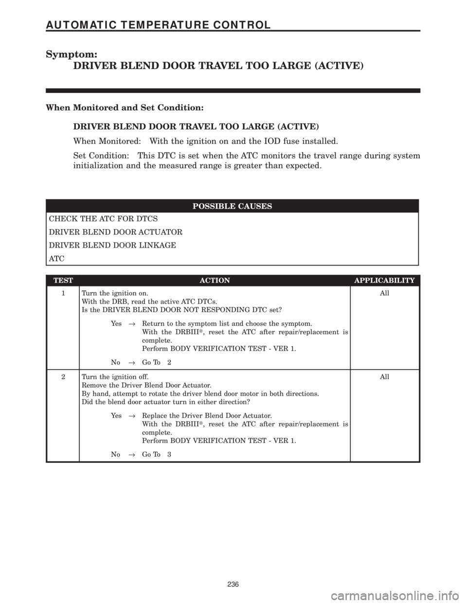
Symptom:
DRIVER BLEND DOOR TRAVEL TOO LARGE (ACTIVE)
When Monitored and Set Condition:
DRIVER BLEND DOOR TRAVEL TOO LARGE (ACTIVE)
When Monitored: With the ignition on and the IOD fuse installed.
Set Condition: This DTC is set when the ATC monitors the travel range during system
initialization and the measured range is greater than expected.
POSSIBLE CAUSES
CHECK THE ATC FOR DTCS
DRIVER BLEND DOOR ACTUATOR
DRIVER BLEND DOOR LINKAGE
AT C
TEST ACTION APPLICABILITY
1 Turn the ignition on.
With the DRB, read the active ATC DTCs.
Is the DRIVER BLEND DOOR NOT RESPONDING DTC set?All
Ye s®Return to the symptom list and choose the symptom.
With the DRBIIIt, reset the ATC after repair/replacement is
complete.
Perform BODY VERIFICATION TEST - VER 1.
No®Go To 2
2 Turn the ignition off.
Remove the Driver Blend Door Actuator.
By hand, attempt to rotate the driver blend door motor in both directions.
Did the blend door actuator turn in either direction?All
Ye s®Replace the Driver Blend Door Actuator.
With the DRBIIIt, reset the ATC after repair/replacement is
complete.
Perform BODY VERIFICATION TEST - VER 1.
No®Go To 3
236
AUTOMATIC TEMPERATURE CONTROL
Page 266 of 4284
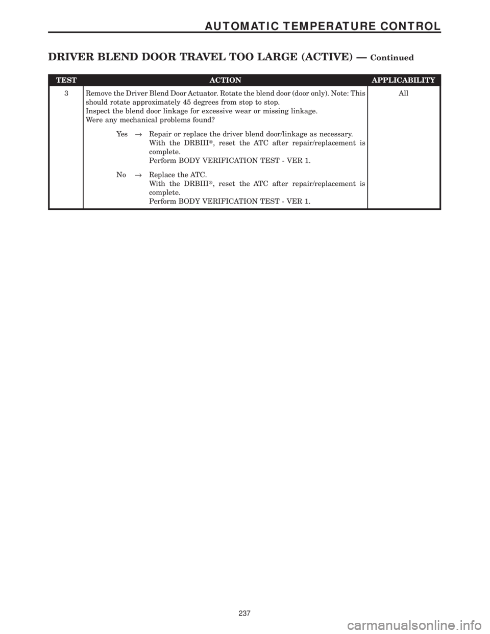
TEST ACTION APPLICABILITY
3 Remove the Driver Blend Door Actuator. Rotate the blend door (door only). Note: This
should rotate approximately 45 degrees from stop to stop.
Inspect the blend door linkage for excessive wear or missing linkage.
Were any mechanical problems found?All
Ye s®Repair or replace the driver blend door/linkage as necessary.
With the DRBIIIt, reset the ATC after repair/replacement is
complete.
Perform BODY VERIFICATION TEST - VER 1.
No®Replace the ATC.
With the DRBIIIt, reset the ATC after repair/replacement is
complete.
Perform BODY VERIFICATION TEST - VER 1.
237
AUTOMATIC TEMPERATURE CONTROL
DRIVER BLEND DOOR TRAVEL TOO LARGE (ACTIVE) ÐContinued
Page 267 of 4284
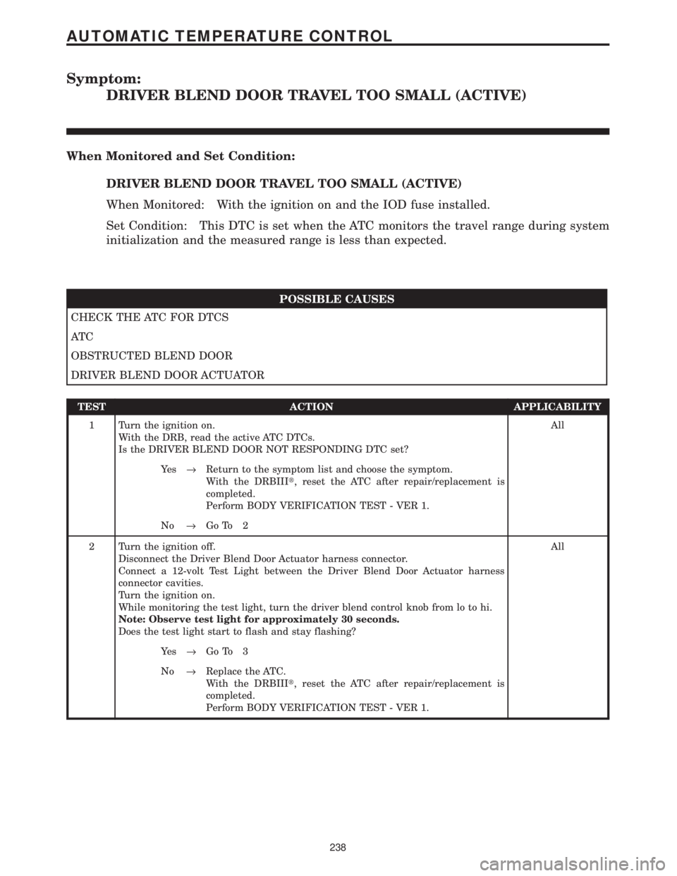
Symptom:
DRIVER BLEND DOOR TRAVEL TOO SMALL (ACTIVE)
When Monitored and Set Condition:
DRIVER BLEND DOOR TRAVEL TOO SMALL (ACTIVE)
When Monitored: With the ignition on and the IOD fuse installed.
Set Condition: This DTC is set when the ATC monitors the travel range during system
initialization and the measured range is less than expected.
POSSIBLE CAUSES
CHECK THE ATC FOR DTCS
AT C
OBSTRUCTED BLEND DOOR
DRIVER BLEND DOOR ACTUATOR
TEST ACTION APPLICABILITY
1 Turn the ignition on.
With the DRB, read the active ATC DTCs.
Is the DRIVER BLEND DOOR NOT RESPONDING DTC set?All
Ye s®Return to the symptom list and choose the symptom.
With the DRBIIIt, reset the ATC after repair/replacement is
completed.
Perform BODY VERIFICATION TEST - VER 1.
No®Go To 2
2 Turn the ignition off.
Disconnect the Driver Blend Door Actuator harness connector.
Connect a 12-volt Test Light between the Driver Blend Door Actuator harness
connector cavities.
Turn the ignition on.
While monitoring the test light, turn the driver blend control knob from lo to hi.
Note: Observe test light for approximately 30 seconds.
Does the test light start to flash and stay flashing?All
Ye s®Go To 3
No®Replace the ATC.
With the DRBIIIt, reset the ATC after repair/replacement is
completed.
Perform BODY VERIFICATION TEST - VER 1.
238
AUTOMATIC TEMPERATURE CONTROL
Page 268 of 4284
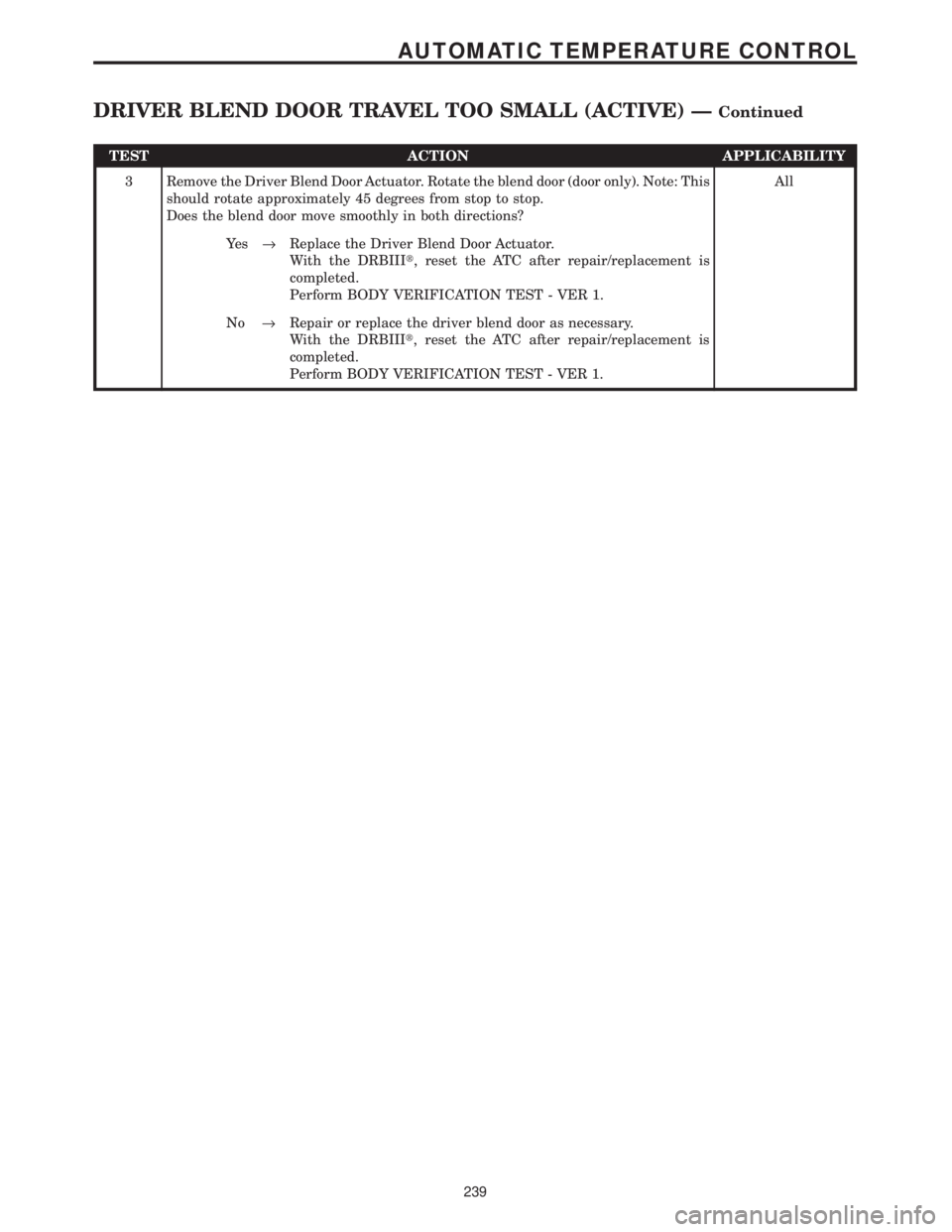
TEST ACTION APPLICABILITY
3 Remove the Driver Blend Door Actuator. Rotate the blend door (door only). Note: This
should rotate approximately 45 degrees from stop to stop.
Does the blend door move smoothly in both directions?All
Ye s®Replace the Driver Blend Door Actuator.
With the DRBIIIt, reset the ATC after repair/replacement is
completed.
Perform BODY VERIFICATION TEST - VER 1.
No®Repair or replace the driver blend door as necessary.
With the DRBIIIt, reset the ATC after repair/replacement is
completed.
Perform BODY VERIFICATION TEST - VER 1.
239
AUTOMATIC TEMPERATURE CONTROL
DRIVER BLEND DOOR TRAVEL TOO SMALL (ACTIVE) ÐContinued
Page 269 of 4284
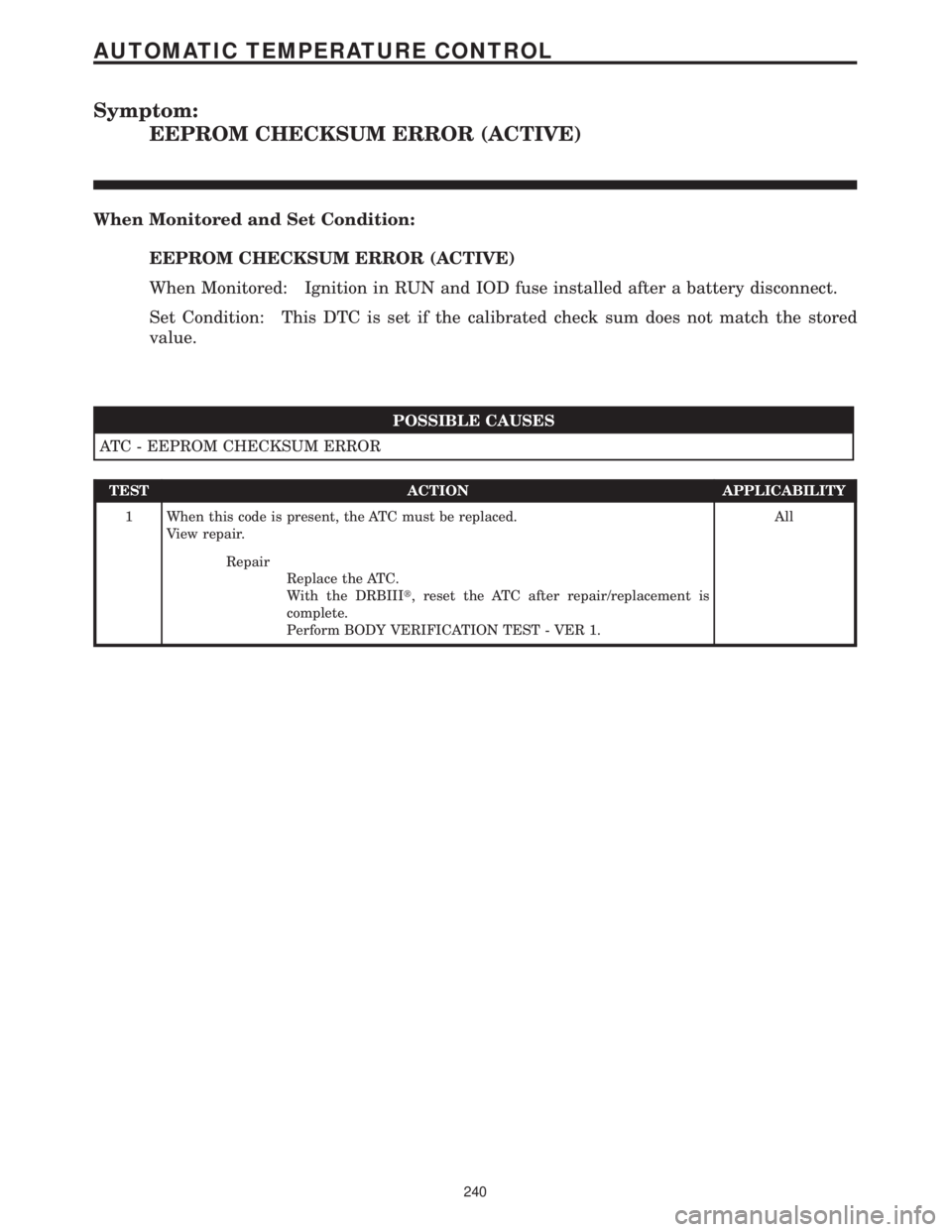
Symptom:
EEPROM CHECKSUM ERROR (ACTIVE)
When Monitored and Set Condition:
EEPROM CHECKSUM ERROR (ACTIVE)
When Monitored: Ignition in RUN and IOD fuse installed after a battery disconnect.
Set Condition: This DTC is set if the calibrated check sum does not match the stored
value.
POSSIBLE CAUSES
ATC - EEPROM CHECKSUM ERROR
TEST ACTION APPLICABILITY
1 When this code is present, the ATC must be replaced.
View repair.All
Repair
Replace the ATC.
With the DRBIIIt, reset the ATC after repair/replacement is
complete.
Perform BODY VERIFICATION TEST - VER 1.
240
AUTOMATIC TEMPERATURE CONTROL
Page 270 of 4284
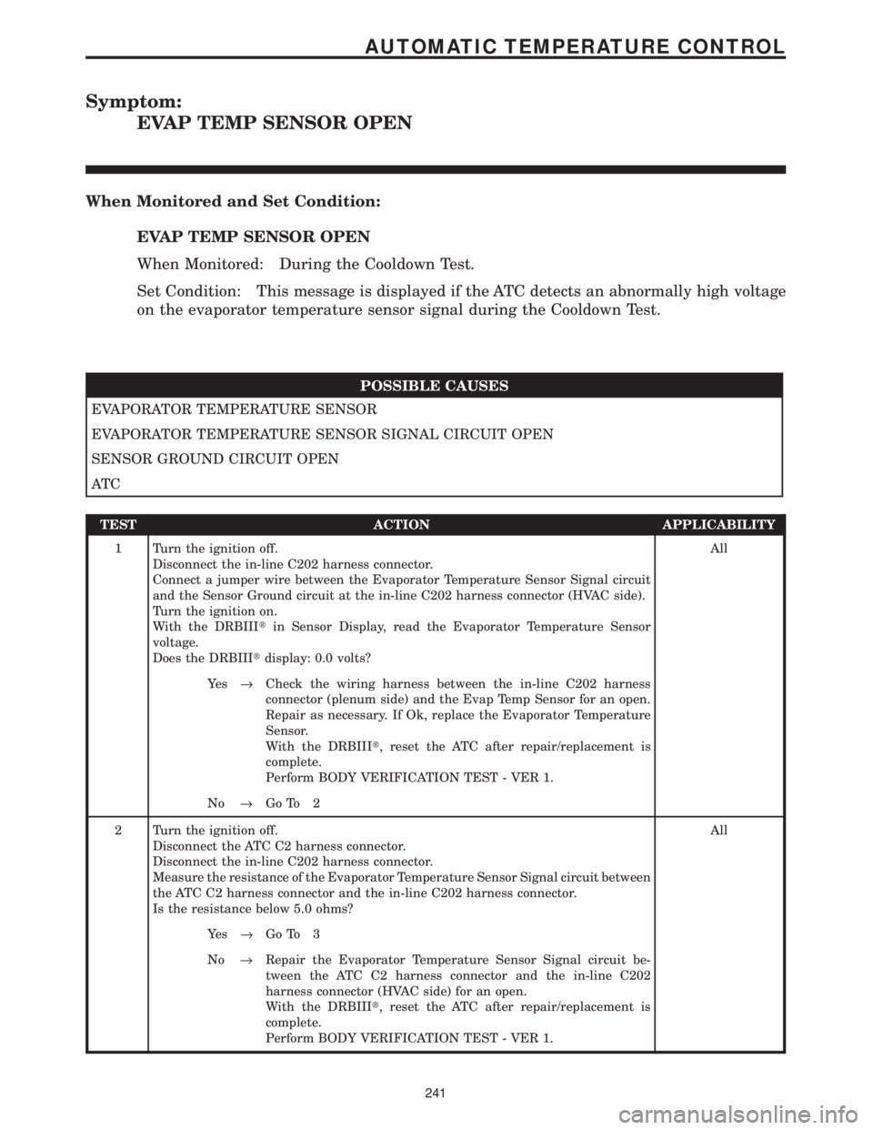
Symptom:
EVAP TEMP SENSOR OPEN
When Monitored and Set Condition:
EVAP TEMP SENSOR OPEN
When Monitored: During the Cooldown Test.
Set Condition: This message is displayed if the ATC detects an abnormally high voltage
on the evaporator temperature sensor signal during the Cooldown Test.
POSSIBLE CAUSES
EVAPORATOR TEMPERATURE SENSOR
EVAPORATOR TEMPERATURE SENSOR SIGNAL CIRCUIT OPEN
SENSOR GROUND CIRCUIT OPEN
AT C
TEST ACTION APPLICABILITY
1 Turn the ignition off.
Disconnect the in-line C202 harness connector.
Connect a jumper wire between the Evaporator Temperature Sensor Signal circuit
and the Sensor Ground circuit at the in-line C202 harness connector (HVAC side).
Turn the ignition on.
With the DRBIIItin Sensor Display, read the Evaporator Temperature Sensor
voltage.
Does the DRBIIItdisplay: 0.0 volts?All
Ye s®Check the wiring harness between the in-line C202 harness
connector (plenum side) and the Evap Temp Sensor for an open.
Repair as necessary. If Ok, replace the Evaporator Temperature
Sensor.
With the DRBIIIt, reset the ATC after repair/replacement is
complete.
Perform BODY VERIFICATION TEST - VER 1.
No®Go To 2
2 Turn the ignition off.
Disconnect the ATC C2 harness connector.
Disconnect the in-line C202 harness connector.
Measure the resistance of the Evaporator Temperature Sensor Signal circuit between
the ATC C2 harness connector and the in-line C202 harness connector.
Is the resistance below 5.0 ohms?All
Ye s®Go To 3
No®Repair the Evaporator Temperature Sensor Signal circuit be-
tween the ATC C2 harness connector and the in-line C202
harness connector (HVAC side) for an open.
With the DRBIIIt, reset the ATC after repair/replacement is
complete.
Perform BODY VERIFICATION TEST - VER 1.
241
AUTOMATIC TEMPERATURE CONTROL