ESP CHRYSLER VOYAGER 2001 Service Manual
[x] Cancel search | Manufacturer: CHRYSLER, Model Year: 2001, Model line: VOYAGER, Model: CHRYSLER VOYAGER 2001Pages: 4284, PDF Size: 83.53 MB
Page 4116 of 4284
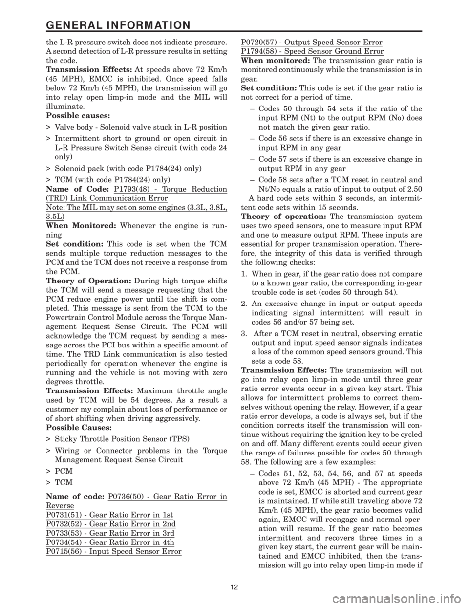
the L-R pressure switch does not indicate pressure.
A second detection of L-R pressure results in setting
the code.
Transmission Effects:At speeds above 72 Km/h
(45 MPH), EMCC is inhibited. Once speed falls
below 72 Km/h (45 MPH), the transmission will go
into relay open limp-in mode and the MIL will
illuminate.
Possible causes:
> Valve body - Solenoid valve stuck in L-R position
> Intermittent short to ground or open circuit in
L-R Pressure Switch Sense circuit (with code 24
only)
> Solenoid pack (with code P1784(24) only)
> TCM (with code P1784(24) only)
Name of Code:P1793(48) - Torque Reduction
(TRD) Link Communication Error
Note: The MIL may set on some engines (3.3L, 3.8L,
3.5L)
When Monitored:Whenever the engine is run-
ning
Set condition:This code is set when the TCM
sends multiple torque reduction messages to the
PCM and the TCM does not receive a response from
the PCM.
Theory of Operation:During high torque shifts
the TCM will send a message requesting that the
PCM reduce engine power until the shift is com-
pleted. This message is sent from the TCM to the
Powertrain Control Module across the Torque Man-
agement Request Sense Circuit. The PCM will
acknowledge the TCM request by sending a mes-
sage across the PCI bus within a specific amount of
time. The TRD Link communication is also tested
periodically for operation whenever the engine is
running and the vehicle is not moving with zero
degrees throttle.
Transmission Effects:Maximum throttle angle
used by TCM will be 54 degrees. As a result a
customer my complain about loss of performance or
of short shifting when driving aggressively.
Possible Causes:
> Sticky Throttle Position Sensor (TPS)
> Wiring or Connector problems in the Torque
Management Request Sense Circuit
> PCM
> TCM
Name of code:P0736(50) - Gear Ratio Error in
Reverse
P0731(51) - Gear Ratio Error in 1st
P0732(52) - Gear Ratio Error in 2nd
P0733(53) - Gear Ratio Error in 3rd
P0734(54) - Gear Ratio Error in 4th
P0715(56) - Input Speed Sensor Error
P0720(57) - Output Speed Sensor Error
P1794(58) - Speed Sensor Ground Error
When monitored:The transmission gear ratio is
monitored continuously while the transmission is in
gear.
Set condition:This code is set if the gear ratio is
not correct for a period of time.
± Codes 50 through 54 sets if the ratio of the
input RPM (Nt) to the output RPM (No) does
not match the given gear ratio.
± Code 56 sets if there is an excessive change in
input RPM in any gear
± Code 57 sets if there is an excessive change in
output RPM in any gear
± Code 58 sets after a TCM reset in neutral and
Nt/No equals a ratio of input to output of 2.50
A hard code sets within 3 seconds, an intermit-
tent code sets within 15 seconds.
Theory of operation:The transmission system
uses two speed sensors, one to measure input RPM
and one to measure output RPM. These inputs are
essential for proper transmission operation. There-
fore, the integrity of this data is verified through
the following checks:
1. When in gear, if the gear ratio does not compare
to a known gear ratio, the corresponding in-gear
trouble code is set (codes 50 through 54).
2. An excessive change in input or output speeds
indicating signal intermittent will result in
codes 56 and/or 57 being set.
3. After a TCM reset in neutral, observing erratic
output and input speed sensor signals indicates
a loss of the common speed sensors ground. This
sets a code 58.
Transmission Effects:The transmission will not
go into relay open limp-in mode until three gear
ratio error events occur in a given key start. This
allows for intermittent problems to correct them-
selves without opening the relay. However, if a gear
ratio error develops, a code is always set, but if the
condition corrects itself the transmission will con-
tinue without requiring the ignition key to be cycled
on and off. Many different events could occur given
the range of failures possible for codes 50 through
58. The following are a few examples:
± Codes 51, 52, 53, 54, 56, and 57 at speeds
above 72 Km/h (45 MPH) - The appropriate
code is set, EMCC is aborted and current gear
is maintained. If while still traveling above 72
Km/h (45 MPH), the gear ratio becomes valid
again, EMCC will reengage and normal oper-
ation will resume. If the gear ratio becomes
intermittent and recovers three times in a
given key start, the current gear will be main-
tained and EMCC inhibited, then the trans-
mission will go into relay open limp-in mode if
12
GENERAL INFORMATION
Page 4119 of 4284

then notice harsh bumps when the A/C clutch is
being cycled, but vehicle shudder will be elimi-
nated. After 35 OBDII (EURO STAGE III OBD)
warm-up starts or if the code is cleared, PEMCC
will be reactivated to see if shudder is still present.
If one shudder event occurs, the code will be reset.
Clearing the code and running battery disconnect
with the DRBIIItis the only way to reset the
shudder counter from 20 back to zero.
Transmission Effects:This code does not cause
the transmission to go into limp-in mode. However,
once the code is set, FEMCC to PEMCC operation
before the A/C clutch engagement will be disabled
for 35 OBDII (EURO STAGE III OBD) warm up
starts.
Possible causes:
> Degraded transmission fluid
> Wheels severely out of alignment
> Internal torque converter problem
Name of Code:P1799(74) - Calculated Oil Temper-
ature in Use
When Monitored:When ever the Engine is run-
ning.
Set condition:The code is set if any of the follow-
ing conditions exist for three consecutive key starts:
> The Temperature Sensor voltage is out of range
(below 0.07 volts or greater than 4.94 volts)
> If continuous erratic Temperature Sensor voltage
is sensed.
> The Temperature Sensor temperature stays be-
low 27C (80ÉF) for an extended period of time.
Theory of Operation:The TCM uses a Tempera-
ture Sensor to monitor the transmission sump tem-
perature. This temperature is used to determine
which shift schedule the TCM is to use. (See Trans-
mission Operation and Shift Scheduling at Various
Sump Temperatures in this diagnostic manual) If
the Temperature Sensor circuit fails to operate
properly the TCM will use the calculated oil tem-
perature routine found in prior model year TCM. If
this occurs for three consecutive key starts, the code
will be set. The TCM will then test the Temperature
Sensor circuit after every 35 OBDII (EURO STAGE
III OBD) warm-up starts. If the Temperature Sen-
sor circuit is OK, the Temperature Sensor data is
used in place of the Calculated Oil Temperature
data.
Transmission Effects:If the Temperature Sensor
indicates a temperature below -18C (0É F) or above
115C (240É F) at start up, The TCM compares the
calculated oil temperature to the indicated Temper-
ature Sensor oil temperature. If the calculated oil
temperature differs significantly from the Temper-
ature Sensor value, the calculated oil temperature
will be used for that key start.Possible Causes:
> Wiring or Connector problems in the transmis-
sion temperature sensor signal circuit.
> TRS
> TCM
Name of Code:P1738(75) - High Temperature
Operation Activated.
When Monitored:Whenever the engine is running.
Set Condition:Immediately once the Overheat
Shift Schedule is activated.
Theory of Operation:If the transmission oil tem-
perature rises above 115C (240ÉF), the overheat
shift schedule is activated refer to Transmission
Operation as a function of Transmission Oil Tem-
perature and the code is set. The DTC is an infor-
mation code only and is being set to aid the techni-
cian in determining root cause of a customer
driveability issue. The code is also intended to alert
the technician to determine if a cooling system
malfunction has occurred or if an additional trans-
mission air to oil cooler should be added to the
vehicle if the customer regularly drives in a manner
that overheats the transmission. Extended opera-
tion above 115C (240ÉF) will reduce the durability of
the transmission and should be avoided. Correcting
the cooling system malfunction or installing an
additional transmission oil cooler will improve
transmission durability especially for customers
who operate in city/construction stop and go traffic,
tow trailers regularly, drive aggressively in low gear
or drive regularly in mountainous areas.
Transmission Effects:Information only code. -
Overheat shift schedule was activated, no limp-in
condition occurs. 2nd gear partial EMCC above 40
Km/h (25 MPH), 3rd gear EMCC from 45-69 Km/h
(28-43 MPH), delayed 3-4 upshift at 69 Km/h (43
MPH), early 4-3 coastdown at 66 Km/h (41 MPH),
EMCC operation under all conditions above 40
Km/h (25 MPH) except at closed throttle or 1st gear.
Possible Causes:
± Transmission Overfilled with Oil
± Engine cooling fan failure
± Engine thermostat stuck closed
± Radiator corroded or packed with dirt
± Transmission Oil Cooler Plugged
± Customer driving pattern requires additional
transmission cooling
Name Of Code:P1739(76) - Power-Up at Speed
When Monitored:When TCM (transmission con-
trol module) initially powers-up.
Set Condition:If the TCM powers up while in the
9Drive9position and the vehicle is going above 32
Km/h (20 MPH), the code is set.
Theory of Operation:If a vehicle loses power to
the TCM, the vehicle will go to the 2nd gear mode
15
GENERAL INFORMATION
Page 4130 of 4284
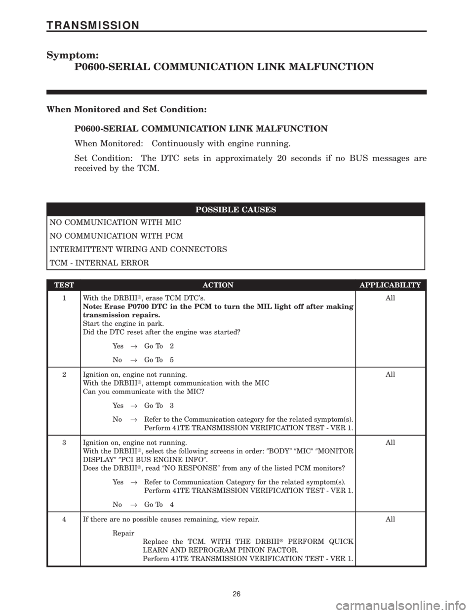
Symptom:
P0600-SERIAL COMMUNICATION LINK MALFUNCTION
When Monitored and Set Condition:
P0600-SERIAL COMMUNICATION LINK MALFUNCTION
When Monitored: Continuously with engine running.
Set Condition: The DTC sets in approximately 20 seconds if no BUS messages are
received by the TCM.
POSSIBLE CAUSES
NO COMMUNICATION WITH MIC
NO COMMUNICATION WITH PCM
INTERMITTENT WIRING AND CONNECTORS
TCM - INTERNAL ERROR
TEST ACTION APPLICABILITY
1 With the DRBIIIt, erase TCM DTC's.
Note: Erase P0700 DTC in the PCM to turn the MIL light off after making
transmission repairs.
Start the engine in park.
Did the DTC reset after the engine was started?All
Ye s®Go To 2
No®Go To 5
2 Ignition on, engine not running.
With the DRBIIIt, attempt communication with the MIC
Can you communicate with the MIC?All
Ye s®Go To 3
No®Refer to the Communication category for the related symptom(s).
Perform 41TE TRANSMISSION VERIFICATION TEST - VER 1.
3 Ignition on, engine not running.
With the DRBIIIt, select the following screens in order:9BODY99MIC99MONITOR
DISPLAY99PCI BUS ENGINE INFO9.
Does the DRBIIIt, read9NO RESPONSE9from any of the listed PCM monitors?All
Ye s®Refer to Communication Category for the related symptom(s).
Perform 41TE TRANSMISSION VERIFICATION TEST - VER 1.
No®Go To 4
4 If there are no possible causes remaining, view repair. All
Repair
Replace the TCM. WITH THE DRBIIItPERFORM QUICK
LEARN AND REPROGRAM PINION FACTOR.
Perform 41TE TRANSMISSION VERIFICATION TEST - VER 1.
26
TRANSMISSION
Page 4155 of 4284

Symptom:
P0731-GEAR RATIO ERROR IN 1ST
When Monitored and Set Condition:
P0731-GEAR RATIO ERROR IN 1ST
When Monitored: The Transmission Gear Ratio is monitored continuously while the
Transmission is in gear.
Set Condition: If the ratio of the input RPM to the output RPM does not match the
current Gear Ratio.
POSSIBLE CAUSES
RELATED DTC'S PRESENT
INTERMITTENT GEAR RATIO ERRORS
TRANSMISSION - INTERNAL
TEST ACTION APPLICABILITY
1NOTE: Low fluid level can be the cause of many Transmission problems. If
the fluid level is low locate and repair the leak then check and adjust the
fluid level per the Service Information.
NOTE: Always perform diagnostics with a fully charged battery to avoid
false symptoms.
With the DRBIIIt, read the engine DTC's. Check and repair all engine DTC's prior
to performing Transmission Symptom Diagnostics.
With the DRBIIIt, read Transmission DTC's. Record all DTC's and 1 Trip Failures.
NOTE: Diagnose 1 Trip Failures as a fully matured DTC.
Using the wiring diagram/schematic as a guide, inspect the wiring and connectors.
Repair as necessary.
Perform the Shift Lever Position Test. If the test does not pass, refer to Symptom test
for P0705 Check Shifter Signal.
For Gear Ratio DTC's, check and record all CVI's.
Most DTC's set on start up but some must be set by driving the vehicle such that all
diagnostic monitors have run.
NOTE: Verify flash level of Transmission Control Module. Some problems
are corrected by software upgrades to the Transmission Control Module.
NOTE: Check for applicable TSB's related to the symptom.
Perform this procedure prior to Symptom diagnosis.All
Continue
Go To 2
2 With the DRBIIIt, read Transmission DTC's
If any of these DTC's are present, perform their respective tests first.
Are DTC's P1791, P0715, P0720, P1794, P1720, present also?All
Ye s®Refer to appropriate symptom in the Transmission category. If
any of these DTC's are present, they will cause a gear ratio error.
Go to test for P1791 first if it is present.
Perform 41TE TRANSMISSION VERIFICATION TEST - VER 1.
No®Go To 3
51
TRANSMISSION
Page 4158 of 4284
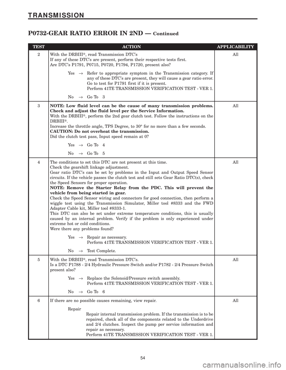
TEST ACTION APPLICABILITY
2 With the DRBIIIt, read Transmission DTC's
If any of these DTC's are present, perform their respective tests first.
Are DTC's P1791, P0715, P0720, P1794, P1720, present also?All
Ye s®Refer to appropriate symptom in the Transmission category. If
any of these DTC's are present, they will cause a gear ratio error.
Go to test for P1791 first if it is present.
Perform 41TE TRANSMISSION VERIFICATION TEST - VER 1.
No®Go To 3
3NOTE: Low fluid level can be the cause of many transmission problems.
Check and adjust the fluid level per the Service Information.
With the DRBIIIt, perform the 2nd gear clutch test. Follow the instructions on the
DRBIIIt.
Increase the throttle angle, TPS Degree, to 30É for no more than a few seconds.
CAUTION: Do not overheat the transmission.
Did the clutch test pass, Input speed remain at 0?All
Ye s®Go To 4
No®Go To 5
4 The conditions to set this DTC are not present at this time.
Check the gearshift linkage adjustment.
Gear ratio DTC's can be set by problems in the Input and Output Speed Sensor
circuits. If the vehicle passes the clutch test and still sets Gear Ratio DTC(s), check
the Speed Sensors for proper operation.
NOTE: Remove the Starter Relay from the PDC. This will prevent the
vehicle from being started in gear.
Check the Speed Sensor wiring and connectors for good connection, then perform a
wiggle test using the Transmission Simulator, Miller tool #8333 and the FWD
Adapter Cable kit, Miller tool #8333-1.
This DTC can also be set under extreme temperature conditions, this is usually
caused by an internal problem. Verify if the problem is only experienced under
extreme hot or cold conditions.
Were there any problems found?All
Ye s®Repair as necessary.
Perform 41TE TRANSMISSION VERIFICATION TEST - VER 1.
No®Test Complete.
5 With the DRBIIIt, read Transmission DTC's.
Is a DTC P1788 - 2/4 Hydraulic Pressure Switch and/or P1782 - 2/4 Pressure Switch
present also?All
Ye s®Replace the Solenoid/Pressure switch assembly.
Perform 41TE TRANSMISSION VERIFICATION TEST - VER 1.
No®Go To 6
6 If there are no possible causes remaining, view repair. All
Repair
Repair internal transmission problem. If the transmission is to be
repaired, check all of the components related to the Underdrive
and 2/4 clutches. Inspect the pump per service information and
repair as necessary.
Perform 41TE TRANSMISSION VERIFICATION TEST - VER 1.
54
TRANSMISSION
P0732-GEAR RATIO ERROR IN 2ND ÐContinued
Page 4160 of 4284
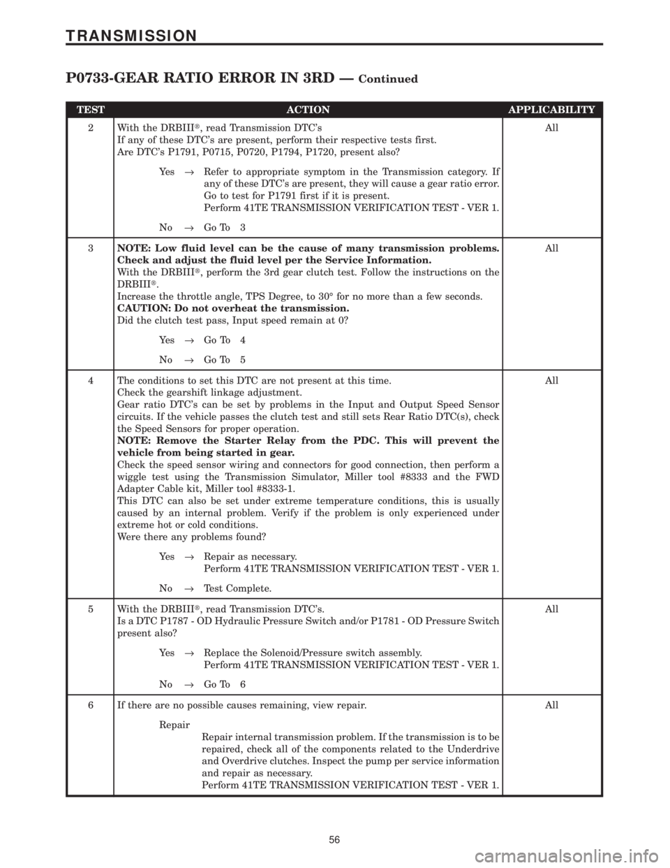
TEST ACTION APPLICABILITY
2 With the DRBIIIt, read Transmission DTC's
If any of these DTC's are present, perform their respective tests first.
Are DTC's P1791, P0715, P0720, P1794, P1720, present also?All
Ye s®Refer to appropriate symptom in the Transmission category. If
any of these DTC's are present, they will cause a gear ratio error.
Go to test for P1791 first if it is present.
Perform 41TE TRANSMISSION VERIFICATION TEST - VER 1.
No®Go To 3
3NOTE: Low fluid level can be the cause of many transmission problems.
Check and adjust the fluid level per the Service Information.
With the DRBIIIt, perform the 3rd gear clutch test. Follow the instructions on the
DRBIIIt.
Increase the throttle angle, TPS Degree, to 30É for no more than a few seconds.
CAUTION: Do not overheat the transmission.
Did the clutch test pass, Input speed remain at 0?All
Ye s®Go To 4
No®Go To 5
4 The conditions to set this DTC are not present at this time.
Check the gearshift linkage adjustment.
Gear ratio DTC's can be set by problems in the Input and Output Speed Sensor
circuits. If the vehicle passes the clutch test and still sets Rear Ratio DTC(s), check
the Speed Sensors for proper operation.
NOTE: Remove the Starter Relay from the PDC. This will prevent the
vehicle from being started in gear.
Check the speed sensor wiring and connectors for good connection, then perform a
wiggle test using the Transmission Simulator, Miller tool #8333 and the FWD
Adapter Cable kit, Miller tool #8333-1.
This DTC can also be set under extreme temperature conditions, this is usually
caused by an internal problem. Verify if the problem is only experienced under
extreme hot or cold conditions.
Were there any problems found?All
Ye s®Repair as necessary.
Perform 41TE TRANSMISSION VERIFICATION TEST - VER 1.
No®Test Complete.
5 With the DRBIIIt, read Transmission DTC's.
Is a DTC P1787 - OD Hydraulic Pressure Switch and/or P1781 - OD Pressure Switch
present also?All
Ye s®Replace the Solenoid/Pressure switch assembly.
Perform 41TE TRANSMISSION VERIFICATION TEST - VER 1.
No®Go To 6
6 If there are no possible causes remaining, view repair. All
Repair
Repair internal transmission problem. If the transmission is to be
repaired, check all of the components related to the Underdrive
and Overdrive clutches. Inspect the pump per service information
and repair as necessary.
Perform 41TE TRANSMISSION VERIFICATION TEST - VER 1.
56
TRANSMISSION
P0733-GEAR RATIO ERROR IN 3RD ÐContinued
Page 4162 of 4284
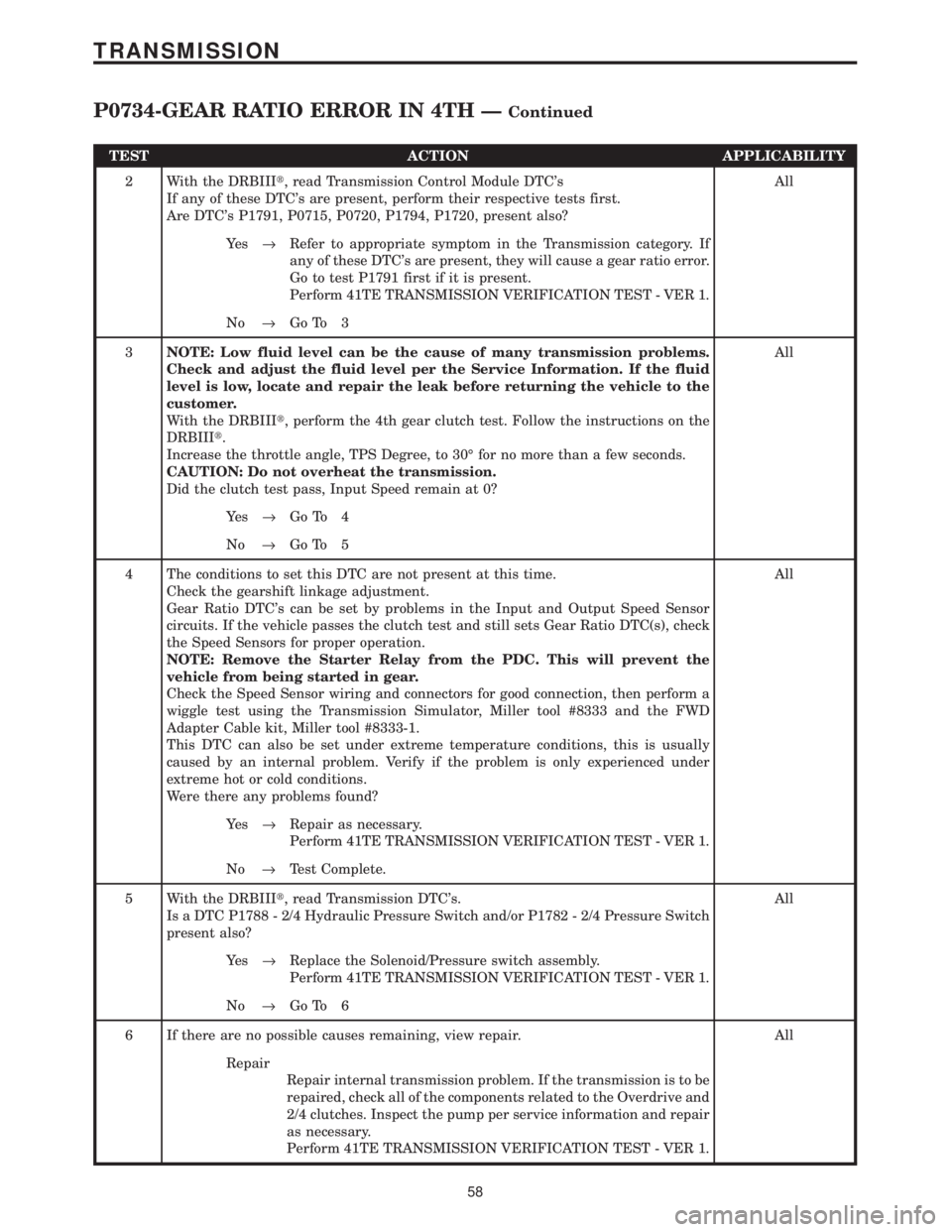
TEST ACTION APPLICABILITY
2 With the DRBIIIt, read Transmission Control Module DTC's
If any of these DTC's are present, perform their respective tests first.
Are DTC's P1791, P0715, P0720, P1794, P1720, present also?All
Ye s®Refer to appropriate symptom in the Transmission category. If
any of these DTC's are present, they will cause a gear ratio error.
Go to test P1791 first if it is present.
Perform 41TE TRANSMISSION VERIFICATION TEST - VER 1.
No®Go To 3
3NOTE: Low fluid level can be the cause of many transmission problems.
Check and adjust the fluid level per the Service Information. If the fluid
level is low, locate and repair the leak before returning the vehicle to the
customer.
With the DRBIIIt, perform the 4th gear clutch test. Follow the instructions on the
DRBIIIt.
Increase the throttle angle, TPS Degree, to 30É for no more than a few seconds.
CAUTION: Do not overheat the transmission.
Did the clutch test pass, Input Speed remain at 0?All
Ye s®Go To 4
No®Go To 5
4 The conditions to set this DTC are not present at this time.
Check the gearshift linkage adjustment.
Gear Ratio DTC's can be set by problems in the Input and Output Speed Sensor
circuits. If the vehicle passes the clutch test and still sets Gear Ratio DTC(s), check
the Speed Sensors for proper operation.
NOTE: Remove the Starter Relay from the PDC. This will prevent the
vehicle from being started in gear.
Check the Speed Sensor wiring and connectors for good connection, then perform a
wiggle test using the Transmission Simulator, Miller tool #8333 and the FWD
Adapter Cable kit, Miller tool #8333-1.
This DTC can also be set under extreme temperature conditions, this is usually
caused by an internal problem. Verify if the problem is only experienced under
extreme hot or cold conditions.
Were there any problems found?All
Ye s®Repair as necessary.
Perform 41TE TRANSMISSION VERIFICATION TEST - VER 1.
No®Test Complete.
5 With the DRBIIIt, read Transmission DTC's.
Is a DTC P1788 - 2/4 Hydraulic Pressure Switch and/or P1782 - 2/4 Pressure Switch
present also?All
Ye s®Replace the Solenoid/Pressure switch assembly.
Perform 41TE TRANSMISSION VERIFICATION TEST - VER 1.
No®Go To 6
6 If there are no possible causes remaining, view repair. All
Repair
Repair internal transmission problem. If the transmission is to be
repaired, check all of the components related to the Overdrive and
2/4 clutches. Inspect the pump per service information and repair
as necessary.
Perform 41TE TRANSMISSION VERIFICATION TEST - VER 1.
58
TRANSMISSION
P0734-GEAR RATIO ERROR IN 4TH ÐContinued
Page 4163 of 4284

Symptom:
P0736-GEAR RATIO ERROR IN REVERSE
When Monitored and Set Condition:
P0736-GEAR RATIO ERROR IN REVERSE
When Monitored: The Transmission Gear Ratio is monitored continuously while the
Transmission is in Gear.
Set Condition: If the ratio of the input RPM to the output RPM does not match the
current Gear Ratio.
POSSIBLE CAUSES
RELATED DTC'S PRESENT
INTERMITTENT GEAR RATIO ERRORS
TRANSMISSION - INTERNAL
TEST ACTION APPLICABILITY
1NOTE: Low fluid level can be the cause of many Transmission problems. If
the fluid level is low locate and repair the leak then check and adjust the
fluid level per the Service Information.
NOTE: Always perform diagnostics with a fully charged battery to avoid
false symptoms.
With the DRBIIIt, read the engine DTC's. Check and repair all engine DTC's prior
to performing Transmission Symptom Diagnostics.
With the DRBIIIt, read Transmission DTC's. Record all DTC's and 1 Trip Failures.
NOTE: Diagnose 1 Trip Failures as a fully matured DTC.
Using the wiring diagram/schematic as a guide, inspect the wiring and connectors.
Repair as necessary.
Perform the Shift Lever Position Test. If the test does not pass, refer to Symptom test
for P0705 Check Shifter Signal.
For Gear Ratio DTC's, check and record all CVI's.
Most DTC's set on start up but some must be set by driving the vehicle such that all
diagnostic monitors have run.
NOTE: Verify flash level of Transmission Control Module. Some problems
are corrected by software upgrades to the Transmission Control Module.
NOTE: Check for applicable TSB's related to the symptom.
Perform this procedure prior to Symptom diagnosis.All
Continue
Go To 2
2 With the DRBIIIt, read Transmission DTC's
If any of these DTC's are present, perform their respective tests first.
Are DTC's P1791, P0715, P0720, P1794, P1720, present also?All
Ye s®Refer to appropriate symptom in the Transmission category. If
any of these DTC's are present, they will cause a gear ratio error.
Go to test for P1791 first if it is present.
No®Go To 3
59
TRANSMISSION
Page 4167 of 4284

Symptom:
P0750-LR SOLENOID CIRCUIT
When Monitored and Set Condition:
P0750-LR SOLENOID CIRCUIT
When Monitored: Initially at power-up, then every 10 seconds thereafter. The solenoids
will also be tested immediately after a Gear Ratio or Pressure Switch error is detected.
Set Condition: Three consecutive solenoid continuity test failures, or one failure if a test
is run in response to a Gear Ratio or Pressure Switch error.
POSSIBLE CAUSES
RELATED RELAY DTC'S PRESENT
INTERMITTENT WIRING AND CONNECTORS
TRANSMISSION CONTROL RELAY OUTPUT CIRCUIT OPEN
L/R SOLENOID CONTROL CIRCUIT OPEN
L/R SOLENOID CONTROL CIRCUIT SHORT TO GROUND
L/R SOLENOID CONTROL CIRCUIT SHORT TO VOLTAGE
L/R SOLENOID INOPERATIVE
TCM - L/R SOLENOID
TEST ACTION APPLICABILITY
1NOTE: Low fluid level can be the cause of many Transmission problems. If
the fluid level is low locate and repair the leak then check and adjust the
fluid level per the Service Information.
NOTE: Always perform diagnostics with a fully charged battery to avoid
false symptoms.
With the DRBIIIt, read the engine DTC's. Check and repair all engine DTC's prior
to performing Transmission Symptom Diagnostics.
With the DRBIIIt, read Transmission DTC's. Record all DTC's and 1 Trip Failures.
NOTE: Diagnose 1 Trip Failures as a fully matured DTC.
Using the wiring diagram/schematic as a guide, inspect the wiring and connectors.
Repair as necessary.
Perform the Shift Lever Position Test. If the test does not pass, refer to Symptom test
for P0705 Check Shifter Signal.
For Gear Ratio DTC's, check and record all CVI's.
Most DTC's set on start up but some must be set by driving the vehicle such that all
diagnostic monitors have run.
NOTE: Verify flash level of Transmission Control Module. Some problems
are corrected by software upgrades to the Transmission Control Module.
NOTE: Check for applicable TSB's related to the symptom.
Perform this procedure prior to Symptom diagnosis.All
Continue
Go To 2
63
TRANSMISSION
Page 4170 of 4284

Symptom:
P0755-2-4 SOLENOID CIRCUIT
When Monitored and Set Condition:
P0755-2-4 SOLENOID CIRCUIT
When Monitored: Initially at power-up, then every 10 seconds thereafter. They will also
be tested immediately after a Gear Ratio or Pressure Switch error is detected.
Set Condition: Three consecutive Solenoid continuity test failures, or one failure if test is
run in response to a Gear Ratio or Pressure Switch error.
POSSIBLE CAUSES
RELATED RELAY DTC'S PRESENT
INTERMITTENT WIRING AND CONNECTORS
TRANSMISSION CONTROL RELAY OUTPUT CIRCUIT OPEN
2-4 SOLENOID CONTROL CIRCUIT OPEN
2-4 SOLENOID CONTROL CIRCUIT SHORT TO GROUND
2-4 SOLENOID CONTROL CIRCUIT SHORT TO VOLTAGE
2-4 SOLENOID
TCM - 2-4 SOLENOID
TEST ACTION APPLICABILITY
1NOTE: Low fluid level can be the cause of many Transmission problems. If
the fluid level is low locate and repair the leak then check and adjust the
fluid level per the Service Information.
NOTE: Always perform diagnostics with a fully charged battery to avoid
false symptoms.
With the DRBIIIt, read the engine DTC's. Check and repair all engine DTC's prior
to performing Transmission Symptom Diagnostics.
With the DRBIIIt, read Transmission DTC's. Record all DTC's and 1 Trip Failures.
NOTE: Diagnose 1 Trip Failures as a fully matured DTC.
Using the wiring diagram/schematic as a guide, inspect the wiring and connectors.
Repair as necessary.
Perform the Shift Lever Position Test. If the test does not pass, refer to Symptom test
for P0705 Check Shifter Signal.
For Gear Ratio DTC's, check and record all CVI's.
Most DTC's set on start up but some must be set by driving the vehicle such that all
diagnostic monitors have run.
NOTE: Verify flash level of Transmission Control Module. Some problems
are corrected by software upgrades to the Transmission Control Module.
NOTE: Check for applicable TSB's related to the symptom.
Perform this procedure prior to Symptom diagnosis.All
Continue
Go To 2
66
TRANSMISSION