key CHRYSLER VOYAGER 2001 Owner's Manual
[x] Cancel search | Manufacturer: CHRYSLER, Model Year: 2001, Model line: VOYAGER, Model: CHRYSLER VOYAGER 2001Pages: 4284, PDF Size: 83.53 MB
Page 63 of 4284
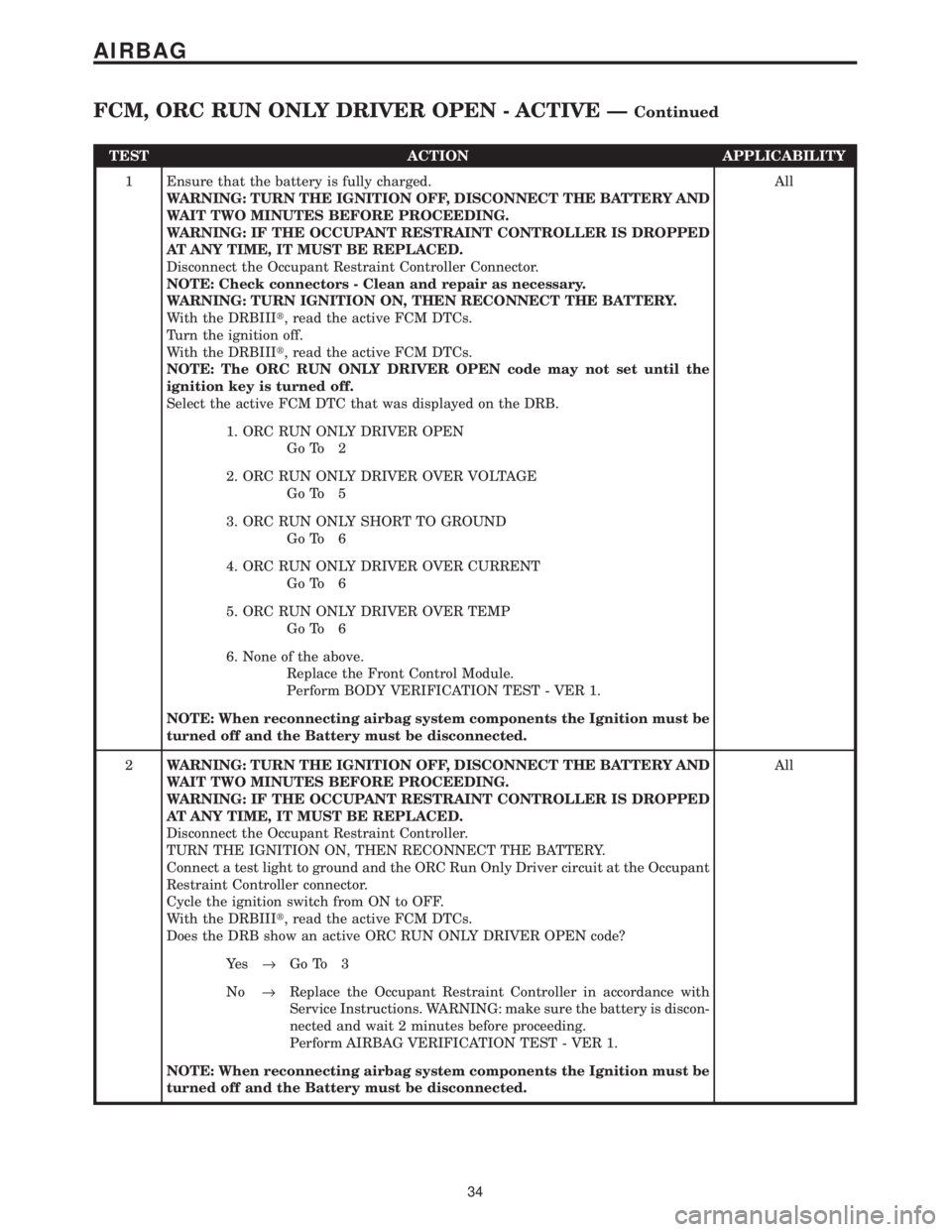
TEST ACTION APPLICABILITY
1 Ensure that the battery is fully charged.
WARNING: TURN THE IGNITION OFF, DISCONNECT THE BATTERY AND
WAIT TWO MINUTES BEFORE PROCEEDING.
WARNING: IF THE OCCUPANT RESTRAINT CONTROLLER IS DROPPED
AT ANY TIME, IT MUST BE REPLACED.
Disconnect the Occupant Restraint Controller Connector.
NOTE: Check connectors - Clean and repair as necessary.
WARNING: TURN IGNITION ON, THEN RECONNECT THE BATTERY.
With the DRBIIIt, read the active FCM DTCs.
Turn the ignition off.
With the DRBIIIt, read the active FCM DTCs.
NOTE: The ORC RUN ONLY DRIVER OPEN code may not set until the
ignition key is turned off.
Select the active FCM DTC that was displayed on the DRB.All
1. ORC RUN ONLY DRIVER OPEN
Go To 2
2. ORC RUN ONLY DRIVER OVER VOLTAGE
Go To 5
3. ORC RUN ONLY SHORT TO GROUND
Go To 6
4. ORC RUN ONLY DRIVER OVER CURRENT
Go To 6
5. ORC RUN ONLY DRIVER OVER TEMP
Go To 6
6. None of the above.
Replace the Front Control Module.
Perform BODY VERIFICATION TEST - VER 1.
NOTE: When reconnecting airbag system components the Ignition must be
turned off and the Battery must be disconnected.
2WARNING: TURN THE IGNITION OFF, DISCONNECT THE BATTERY AND
WAIT TWO MINUTES BEFORE PROCEEDING.
WARNING: IF THE OCCUPANT RESTRAINT CONTROLLER IS DROPPED
AT ANY TIME, IT MUST BE REPLACED.
Disconnect the Occupant Restraint Controller.
TURN THE IGNITION ON, THEN RECONNECT THE BATTERY.
Connect a test light to ground and the ORC Run Only Driver circuit at the Occupant
Restraint Controller connector.
Cycle the ignition switch from ON to OFF.
With the DRBIIIt, read the active FCM DTCs.
Does the DRB show an active ORC RUN ONLY DRIVER OPEN code?All
Ye s®Go To 3
No®Replace the Occupant Restraint Controller in accordance with
Service Instructions. WARNING: make sure the battery is discon-
nected and wait 2 minutes before proceeding.
Perform AIRBAG VERIFICATION TEST - VER 1.
NOTE: When reconnecting airbag system components the Ignition must be
turned off and the Battery must be disconnected.
34
AIRBAG
FCM, ORC RUN ONLY DRIVER OPEN - ACTIVE ÐContinued
Page 72 of 4284
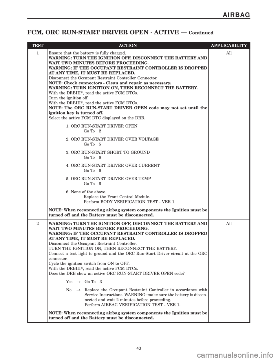
TEST ACTION APPLICABILITY
1 Ensure that the battery is fully charged.
WARNING: TURN THE IGNITION OFF, DISCONNECT THE BATTERY AND
WAIT TWO MINUTES BEFORE PROCEEDING.
WARNING: IF THE OCCUPANT RESTRAINT CONTROLLER IS DROPPED
AT ANY TIME, IT MUST BE REPLACED.
Disconnect the Occupant Restraint Controller Connector.
NOTE: Check connectors - Clean and repair as necessary.
WARNING: TURN IGNITION ON, THEN RECONNECT THE BATTERY.
With the DRBIIIt, read the active FCM DTCs.
Turn the ignition off.
With the DRBIIIt, read the active FCM DTCs.
NOTE: The ORC RUN-START DRIVER OPEN code may not set until the
ignition key is turned off.
Select the active FCM DTC displayed on the DRB.All
1. ORC RUN-START DRIVER OPEN
Go To 2
2. ORC RUN-START DRIVER OVER VOLTAGE
Go To 5
3. ORC RUN-START SHORT TO GROUND
Go To 6
4. ORC RUN-START DRIVER OVER CURRENT
Go To 6
5. ORC RUN-START DRIVER OVER TEMP
Go To 6
6. None of the above.
Replace the Front Control Module.
Perform BODY VERIFICATION TEST - VER 1.
NOTE: When reconnecting airbag system components the Ignition must be
turned off and the Battery must be disconnected.
2WARNING: TURN THE IGNITION OFF, DISCONNECT THE BATTERY AND
WAIT TWO MINUTES BEFORE PROCEEDING.
WARNING: IF THE OCCUPANT RESTRAINT CONTROLLER IS DROPPED
AT ANY TIME, IT MUST BE REPLACED.
Disconnect the Occupant Restraint Controller.
TURN THE IGNITION ON, THEN RECONNECT THE BATTERY.
Connect a test light to ground and the ORC Run-Start Driver circuit at the ORC
connector.
Cycle the ignition switch from ON to OFF.
With the DRBIIIt, read the active FCM DTCs.
Does the DRB show an active ORC RUN-START DRIVER OPEN code?All
Ye s®Go To 3
No®Replace the Occupant Restraint Controller in accordance with
Service Instructions. WARNING: make sure the battery is discon-
nected and wait 2 minutes before proceeding.
Perform AIRBAG VERIFICATION TEST - VER 1.
NOTE: When reconnecting airbag system components the Ignition must be
turned off and the Battery must be disconnected.
43
AIRBAG
FCM, ORC RUN-START DRIVER OPEN - ACTIVE ÐContinued
Page 77 of 4284

TEST ACTION APPLICABILITY
1 Ensure that the battery is fully charged.
Turn the ignition on.
With the DRBIIIt, read the active FCM DTCs.
NOTE: The SIACM RUN-START DRIVER OPEN code may not set until the
ignition key is turned off.
Turn the ignition off.
With the DRBIIIt, read the active SIACM FCM Diagnostic Trouble Codes.
Select the active SIACM FCM code displayed on the DRB.All
1. SIACM RUN-START DRIVER OPEN
Go To 2
2. SIACM RUN-START DRIVER OVER VOLTAGE
Go To 7
3. SIACM RUN-START SHORT TO GROUND
Go To 8
4. SIACM RUN-START DRIVER OVER CURRENT
Go To 8
5. SIACM RUN-START DRIVER OVER TEMP
Go To 8
NOTE: When reconnecting airbag system components the Ignition must be
turned off and the Battery must be disconnected.
2WARNING: TURN THE IGNITION OFF, DISCONNECT THE BATTERY AND
WAIT TWO MINUTES BEFORE PROCEEDING.
WARNING: IF THE SIDE IMPACT AIRBAG CONTROL MODULE IS
DROPPED AT ANY TIME, IT MUST BE REPLACED.
Disconnect the Left Side Impact Airbag Control Module.
NOTE: When the ignition key is turned off, the FCM will supply a diagnostic
voltage to the SIACM Run-Start Driver circuit for approximately 60 sec-
onds.
Measure the voltage of the SIACM Run-Start Driver circuit between the Left Side
Impact Airbag Control Module connector and ground.
Turn the ignition switch ON and observe the diagnostic voltage on the SIACM
Run-Start circuit.
Select the results from the list below?All
Is the voltage between 1.0 and 2.2 volts
Replace the Front Control Module.
Perform BODY VERIFICATION TEST - VER 1.
Is the voltage between 2.4 and 5.0 volts
Go To 3
No Voltage present?
Go To 4
NOTE: When reconnecting airbag system components the Ignition must be
turned off and the Battery must be disconnected.
48
AIRBAG
FCM, SIACM RUN-START DRIVER OPEN - ACTIVE ÐContinued
Page 111 of 4284
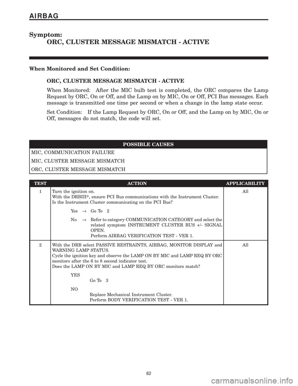
Symptom:
ORC, CLUSTER MESSAGE MISMATCH - ACTIVE
When Monitored and Set Condition:
ORC, CLUSTER MESSAGE MISMATCH - ACTIVE
When Monitored: After the MIC bulb test is completed, the ORC compares the Lamp
Request by ORC, On or Off, and the Lamp on by MIC, On or Off, PCI Bus messages. Each
message is transmitted one time per second or when a change in the lamp state occur.
Set Condition: If the Lamp Request by ORC, On or Off, and the Lamp on by MIC, On or
Off, messages do not match, the code will set.
POSSIBLE CAUSES
MIC, COMMUNICATION FAILURE
MIC, CLUSTER MESSAGE MISMATCH
ORC, CLUSTER MESSAGE MISMATCH
TEST ACTION APPLICABILITY
1 Turn the ignition on.
With the DRBIIIt, ensure PCI Bus communications with the Instrument Cluster.
Is the Instrument Cluster communicating on the PCI Bus?All
Ye s®Go To 2
No®Refer to category COMMUNICATION CATEGORY and select the
related symptom INSTRUMENT CLUSTER BUS +/- SIGNAL
OPEN.
Perform AIRBAG VERIFICATION TEST - VER 1.
2 With the DRB select PASSIVE RESTRAINTS, AIRBAG, MONITOR DISPLAY and
WARNING LAMP STATUS.
Cycle the ignition key and observe the LAMP ON BY MIC and LAMP REQ BY ORC
monitors after the 6 to 8 second indicator test.
Does the LAMP ON BY MIC and LAMP REQ BY ORC monitors match?All
YES
Go To 3
NO
Replace Mechanical Instrument Cluster.
Perform BODY VERIFICATION TEST - VER 1.
82
AIRBAG
Page 155 of 4284
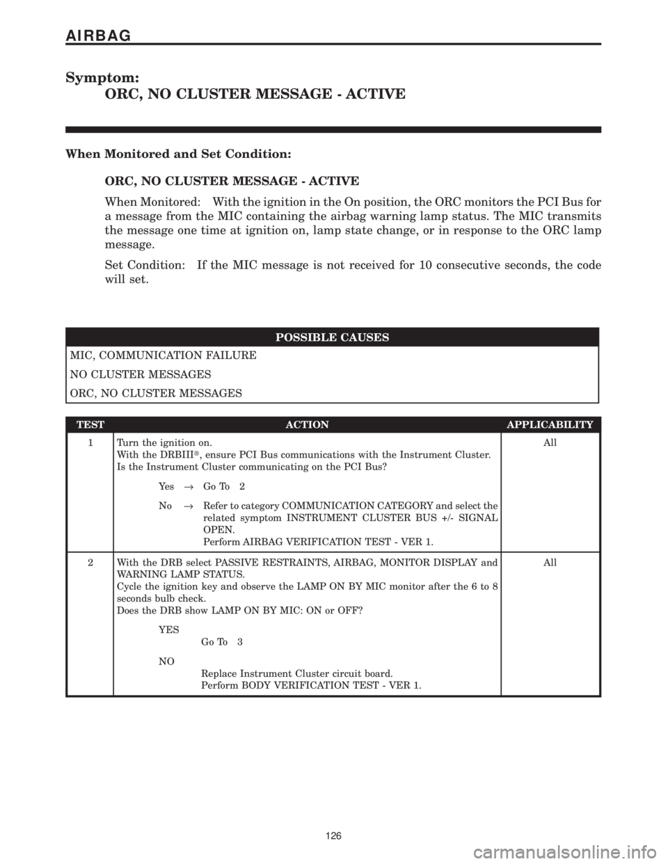
Symptom:
ORC, NO CLUSTER MESSAGE - ACTIVE
When Monitored and Set Condition:
ORC, NO CLUSTER MESSAGE - ACTIVE
When Monitored: With the ignition in the On position, the ORC monitors the PCI Bus for
a message from the MIC containing the airbag warning lamp status. The MIC transmits
the message one time at ignition on, lamp state change, or in response to the ORC lamp
message.
Set Condition: If the MIC message is not received for 10 consecutive seconds, the code
will set.
POSSIBLE CAUSES
MIC, COMMUNICATION FAILURE
NO CLUSTER MESSAGES
ORC, NO CLUSTER MESSAGES
TEST ACTION APPLICABILITY
1 Turn the ignition on.
With the DRBIIIt, ensure PCI Bus communications with the Instrument Cluster.
Is the Instrument Cluster communicating on the PCI Bus?All
Ye s®Go To 2
No®Refer to category COMMUNICATION CATEGORY and select the
related symptom INSTRUMENT CLUSTER BUS +/- SIGNAL
OPEN.
Perform AIRBAG VERIFICATION TEST - VER 1.
2 With the DRB select PASSIVE RESTRAINTS, AIRBAG, MONITOR DISPLAY and
WARNING LAMP STATUS.
Cycle the ignition key and observe the LAMP ON BY MIC monitor after the 6 to 8
seconds bulb check.
Does the DRB show LAMP ON BY MIC: ON or OFF?All
YES
Go To 3
NO
Replace Instrument Cluster circuit board.
Perform BODY VERIFICATION TEST - VER 1.
126
AIRBAG
Page 255 of 4284
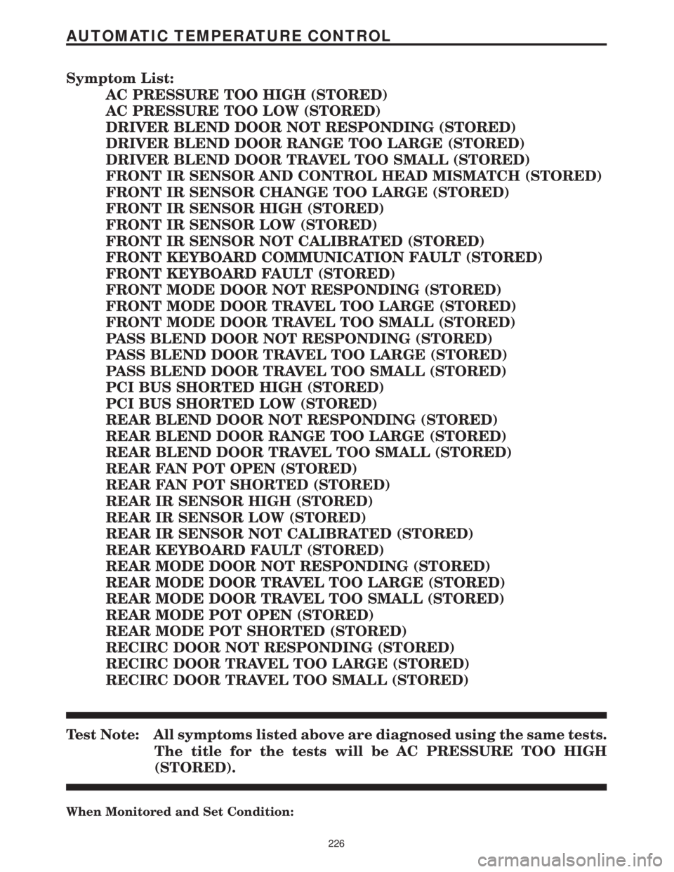
Symptom List:
AC PRESSURE TOO HIGH (STORED)
AC PRESSURE TOO LOW (STORED)
DRIVER BLEND DOOR NOT RESPONDING (STORED)
DRIVER BLEND DOOR RANGE TOO LARGE (STORED)
DRIVER BLEND DOOR TRAVEL TOO SMALL (STORED)
FRONT IR SENSOR AND CONTROL HEAD MISMATCH (STORED)
FRONT IR SENSOR CHANGE TOO LARGE (STORED)
FRONT IR SENSOR HIGH (STORED)
FRONT IR SENSOR LOW (STORED)
FRONT IR SENSOR NOT CALIBRATED (STORED)
FRONT KEYBOARD COMMUNICATION FAULT (STORED)
FRONT KEYBOARD FAULT (STORED)
FRONT MODE DOOR NOT RESPONDING (STORED)
FRONT MODE DOOR TRAVEL TOO LARGE (STORED)
FRONT MODE DOOR TRAVEL TOO SMALL (STORED)
PASS BLEND DOOR NOT RESPONDING (STORED)
PASS BLEND DOOR TRAVEL TOO LARGE (STORED)
PASS BLEND DOOR TRAVEL TOO SMALL (STORED)
PCI BUS SHORTED HIGH (STORED)
PCI BUS SHORTED LOW (STORED)
REAR BLEND DOOR NOT RESPONDING (STORED)
REAR BLEND DOOR RANGE TOO LARGE (STORED)
REAR BLEND DOOR TRAVEL TOO SMALL (STORED)
REAR FAN POT OPEN (STORED)
REAR FAN POT SHORTED (STORED)
REAR IR SENSOR HIGH (STORED)
REAR IR SENSOR LOW (STORED)
REAR IR SENSOR NOT CALIBRATED (STORED)
REAR KEYBOARD FAULT (STORED)
REAR MODE DOOR NOT RESPONDING (STORED)
REAR MODE DOOR TRAVEL TOO LARGE (STORED)
REAR MODE DOOR TRAVEL TOO SMALL (STORED)
REAR MODE POT OPEN (STORED)
REAR MODE POT SHORTED (STORED)
RECIRC DOOR NOT RESPONDING (STORED)
RECIRC DOOR TRAVEL TOO LARGE (STORED)
RECIRC DOOR TRAVEL TOO SMALL (STORED)
Test Note: All symptoms listed above are diagnosed using the same tests.
The title for the tests will be AC PRESSURE TOO HIGH
(STORED).
When Monitored and Set Condition:
226
AUTOMATIC TEMPERATURE CONTROL
Page 275 of 4284

Symptom List:
FRONT IR SENSOR NOT CALIBRATED (ACTIVE)
FRONT KEYBOARD FAULT (ACTIVE)
Test Note: All symptoms listed above are diagnosed using the same tests.
The title for the tests will be FRONT IR SENSOR NOT
CALIBRATED (ACTIVE).
When Monitored and Set Condition:
FRONT IR SENSOR NOT CALIBRATED (ACTIVE)
When Monitored: With the ignition on and the IOD fuse installed.
Set Condition: This DTC is set if the ATC cannot read the IR sensor values or the IR
sensor values are not within a defined range of the HVAC air door motor counts.
POSSIBLE CAUSES
ATC - PROTECTED IGNITION CIRCUIT FAULT
KDB 2 CLOCK CIRCUIT SHORTED TO VOLTAGE
KDB 2 DATA CIRCUIT SHORTED TO GROUND
KDB 2 DATA CIRCUIT SHORTED TO VOLTAGE
PROTECTED IGNITION CIRCUIT OPEN
SENSOR RETURN CIRCUIT OPEN
KDB 2 CLOCK CIRCUIT SHORTED TO GROUND
KDB 2 DATA CIRCUIT OPEN
ATC - KDB 2 DATA CIRCUIT FAULT
ATC - SENSOR RETURN CIRCUIT FAULT
KDB 2 CLOCK CIRCUIT OPEN
ATC - KDB 2 CLOCK CIRCUIT FAULT
ATC REMOTE SENSOR
TEST ACTION APPLICABILITY
1 Turn the ignition off.
Disconnect the ATC Remote Sensor harness connector.
Turn the ignition on.
Measure the voltage of the Protected Ignition circuit.
Is the voltage above 10.0 volts?All
Ye s®Go To 2
No®Go To 16
246
AUTOMATIC TEMPERATURE CONTROL
Page 280 of 4284
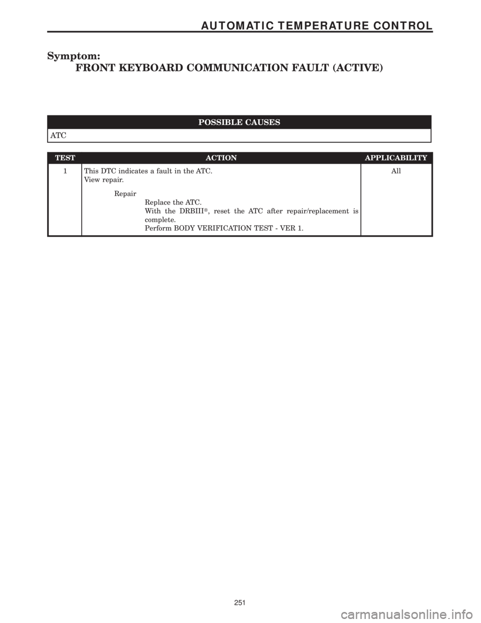
Symptom:
FRONT KEYBOARD COMMUNICATION FAULT (ACTIVE)
POSSIBLE CAUSES
AT C
TEST ACTION APPLICABILITY
1 This DTC indicates a fault in the ATC.
View repair.All
Repair
Replace the ATC.
With the DRBIIIt, reset the ATC after repair/replacement is
complete.
Perform BODY VERIFICATION TEST - VER 1.
251
AUTOMATIC TEMPERATURE CONTROL
Page 309 of 4284

Symptom:
REAR KEYBOARD FAULT (ACTIVE)
POSSIBLE CAUSES
BCM
IGNITION SWITCH (RUN) CIRCUIT OPEN
KDB CLOCK CIRCUIT SHORTED TO VOLTAGE
KDB DATA CIRCUIT SHORTED TO GROUND
KDB DATA CIRCUIT SHORTED TO VOLTAGE
KDB CLOCK CIRCUIT SHORTED TO GROUND
KDB DATA CIRCUIT OPEN
ATC - KDB DATA CIRCUIT FAULT
KDB CLOCK CIRCUIT OPEN
ATC - KDB CLOCK CIRCUIT FAULT
REAR ATC SWITCH GROUND CIRCUIT OPEN
REAR AUTOMATIC TEMPERATURE CONTROL SWITCH
TEST ACTION APPLICABILITY
1 Turn the ignition off.
Disconnect the Rear Automatic Temperature Control Switch harness connector.
Measure the resistance of the Rear ATC Switch Ground circuit.
Is the resistance below 5.0 ohms?All
Ye s®Go To 2
No®Repair the Rear ATC Switch Ground circuit for an open.
With the DRBIIIt, reset the ATC after repair/replacement is
complete.
Perform BODY VERIFICATION TEST - VER 1.
2 Turn the ignition off.
Disconnect the Rear Automatic Temperature Control Switch harness connector.
Turn the ignition on.
Measure the voltage of the Ignition Switch (Run) circuit.
Is the voltage above 10.0 volts?All
Ye s®Go To 3
No®Go To 14
3 Turn the ignition off.
Disconnect the Rear Automatic Temperature Control Switch harness connector.
Turn the ignition on.
Measure the voltage of the KDB Data circuit.
Is the voltage above 10.0 volts?All
Ye s®Go To 4
No®Go To 11
280
AUTOMATIC TEMPERATURE CONTROL
Page 310 of 4284

TEST ACTION APPLICABILITY
4 Turn the ignition off.
Disconnect the Rear Automatic Temperature Control Switch harness connector.
Disconnect the ATC C2 harness connector.
Turn the ignition on.
Measure the voltage of the KDB Data circuit.
Is the voltage above 1.0 volt?All
Ye s®Repair the KDB Data circuit for a short to voltage.
With the DRBIIIt, reset the ATC after repair/replacement is
complete.
Perform BODY VERIFICATION TEST - VER 1.
No®Go To 5
5 Turn the ignition off.
Disconnect the Rear Automatic Temperature Control Switch harness connector.
Use Scope input cable CH7058, Cable to Probe adapter CH7062, and the red and
black test probes.
Connect the scope input cable to the channel one connector on the DRB. Attach the
red and black leads and the cable to probe adapter to the scope input cable.
Select Lab Scope.
Select Live.
Select 12 volt square wave.
Press F2 for Scope.
Press F2 and use the arrows to set the voltage range to 20 volts, the Offset to 4.0, and
the Probe to x10. Press F2 again and set the divisions to 40ms/Div, then press F2
again when complete.
Connect the Black lead to the chassis ground. Connect the Red lead to the KDB Clock
circuit in the Rear Automatic Temperature Control Switch harness connector.
Turn the ignition on.
Observe the voltage display on the DRB Lab Scope.
NOTE: The lab scope pattern should look similar to the example given in the
support material and cycle from approximately 0 volts to 8.0 volts.
Did the lab scope pattern and voltage react as noted above?All
Ye s®Go To 6
No®Go To 7
6 If there are no possible causes remaining, view repair. All
Repair
Replace the Rear Automatic Temperature Control Switch.
With the DRBIIIt, reset the ATC after repair/replacement is
complete.
Perform BODY VERIFICATION TEST - VER 1.
7 Turn the ignition off.
Disconnect the Rear Automatic Temperature Control Switch harness connector.
Disconnect the ATC C2 harness connector.
Turn the ignition on.
Measure the voltage of the KDB Clock circuit.
Is the voltage above 1.0 volt?All
Ye s®Repair the KDB Clock circuit for a short to voltage.
With the DRBIIIt, reset the ATC after repair/replacement is
complete.
Perform BODY VERIFICATION TEST - VER 1.
No®Go To 8
281
AUTOMATIC TEMPERATURE CONTROL
REAR KEYBOARD FAULT (ACTIVE) ÐContinued