key CHRYSLER VOYAGER 2001 Owner's Guide
[x] Cancel search | Manufacturer: CHRYSLER, Model Year: 2001, Model line: VOYAGER, Model: CHRYSLER VOYAGER 2001Pages: 4284, PDF Size: 83.53 MB
Page 311 of 4284
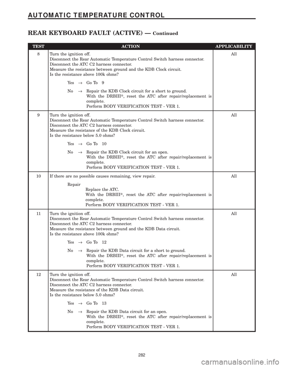
TEST ACTION APPLICABILITY
8 Turn the ignition off.
Disconnect the Rear Automatic Temperature Control Switch harness connector.
Disconnect the ATC C2 harness connector.
Measure the resistance between ground and the KDB Clock circuit.
Is the resistance above 100k ohms?All
Ye s®Go To 9
No®Repair the KDB Clock circuit for a short to ground.
With the DRBIIIt, reset the ATC after repair/replacement is
complete.
Perform BODY VERIFICATION TEST - VER 1.
9 Turn the ignition off.
Disconnect the Rear Automatic Temperature Control Switch harness connector.
Disconnect the ATC C2 harness connector.
Measure the resistance of the KDB Clock circuit.
Is the resistance below 5.0 ohms?All
Ye s®Go To 10
No®Repair the KDB Clock circuit for an open.
With the DRBIIIt, reset the ATC after repair/replacement is
complete.
Perform BODY VERIFICATION TEST - VER 1.
10 If there are no possible causes remaining, view repair. All
Repair
Replace the ATC.
With the DRBIIIt, reset the ATC after repair/replacement is
complete.
Perform BODY VERIFICATION TEST - VER 1.
11 Turn the ignition off.
Disconnect the Rear Automatic Temperature Control Switch harness connector.
Disconnect the ATC C2 harness connector.
Measure the resistance between ground and the KDB Data circuit.
Is the resistance above 100k ohms?All
Ye s®Go To 12
No®Repair the KDB Data circuit for a short to ground.
With the DRBIIIt, reset the ATC after repair/replacement is
complete.
Perform BODY VERIFICATION TEST - VER 1.
12 Turn the ignition off.
Disconnect the Rear Automatic Temperature Control Switch harness connector.
Disconnect the ATC C2 harness connector.
Measure the resistance of the KDB Data circuit.
Is the resistance below 5.0 ohms?All
Ye s®Go To 13
No®Repair the KDB Data circuit for an open.
With the DRBIIIt, reset the ATC after repair/replacement is
complete.
Perform BODY VERIFICATION TEST - VER 1.
282
AUTOMATIC TEMPERATURE CONTROL
REAR KEYBOARD FAULT (ACTIVE) ÐContinued
Page 312 of 4284
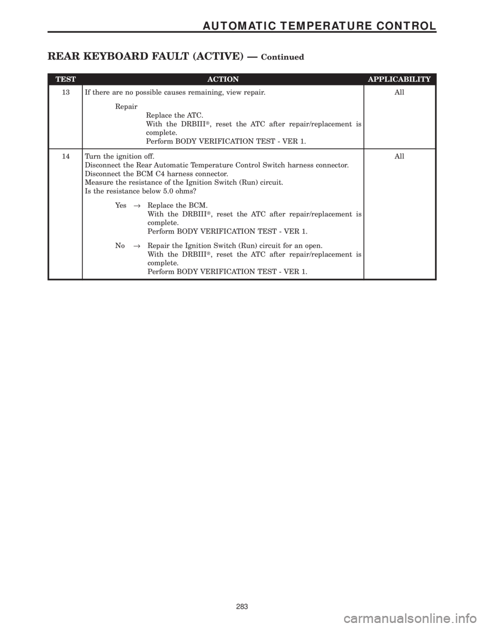
TEST ACTION APPLICABILITY
13 If there are no possible causes remaining, view repair. All
Repair
Replace the ATC.
With the DRBIIIt, reset the ATC after repair/replacement is
complete.
Perform BODY VERIFICATION TEST - VER 1.
14 Turn the ignition off.
Disconnect the Rear Automatic Temperature Control Switch harness connector.
Disconnect the BCM C4 harness connector.
Measure the resistance of the Ignition Switch (Run) circuit.
Is the resistance below 5.0 ohms?All
Ye s®Replace the BCM.
With the DRBIIIt, reset the ATC after repair/replacement is
complete.
Perform BODY VERIFICATION TEST - VER 1.
No®Repair the Ignition Switch (Run) circuit for an open.
With the DRBIIIt, reset the ATC after repair/replacement is
complete.
Perform BODY VERIFICATION TEST - VER 1.
283
AUTOMATIC TEMPERATURE CONTROL
REAR KEYBOARD FAULT (ACTIVE) ÐContinued
Page 365 of 4284
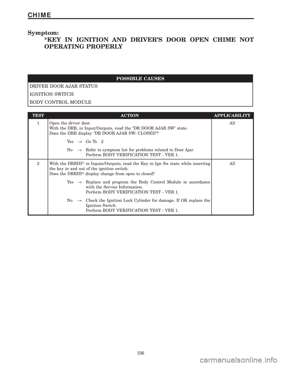
Symptom:
*KEY IN IGNITION AND DRIVER'S DOOR OPEN CHIME NOT
OPERATING PROPERLY
POSSIBLE CAUSES
DRIVER DOOR AJAR STATUS
IGNITION SWITCH
BODY CONTROL MODULE
TEST ACTION APPLICABILITY
1 Open the driver door.
With the DRB, in Input/Outputs, read the9DR DOOR AJAR SW9state.
Does the DRB display9DR DOOR AJAR SW: CLOSED9?All
Ye s®Go To 2
No®Refer to symptom list for problems related to Door Ajar.
Perform BODY VERIFICATION TEST - VER 1.
2 With the DRBIIItin Inputs/Outputs, read the Key in Ign Sw state while inserting
the key in and out of the ignition switch.
Does the DRBIIItdisplay change from open to closed?All
Ye s®Replace and program the Body Control Module in accordance
with the Service Information.
Perform BODY VERIFICATION TEST - VER 1.
No®Check the Ignition Lock Cylinder for damage. If OK replace the
Ignition Switch.
Perform BODY VERIFICATION TEST - VER 1.
336
CHIME
Page 400 of 4284
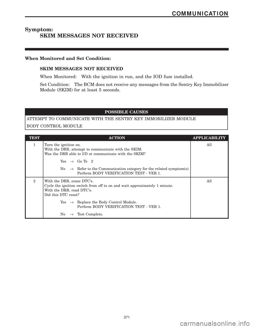
Symptom:
SKIM MESSAGES NOT RECEIVED
When Monitored and Set Condition:
SKIM MESSAGES NOT RECEIVED
When Monitored: With the ignition in run, and the IOD fuse installed.
Set Condition: The BCM does not receive any messages from the Sentry Key Immobilizer
Module (SKIM) for at least 5 seconds.
POSSIBLE CAUSES
ATTEMPT TO COMMUNICATE WITH THE SENTRY KEY IMMOBILIZER MODULE
BODY CONTROL MODULE
TEST ACTION APPLICABILITY
1 Turn the ignition on.
With the DRB, attempt to communicate with the SKIM.
Was the DRB able to I/D or communicate with the SKIM?All
Ye s®Go To 2
No®Refer to the Communication category for the related symptom(s).
Perform BODY VERIFICATION TEST - VER 1.
2 With the DRB, erase DTC's.
Cycle the ignition switch from off to on and wait approximately 1 minute.
With the DRB, read DTC's.
Did this DTC reset?All
Ye s®Replace the Body Control Module.
Perform BODY VERIFICATION TEST - VER 1.
No®Test Complete.
371
COMMUNICATION
Page 406 of 4284
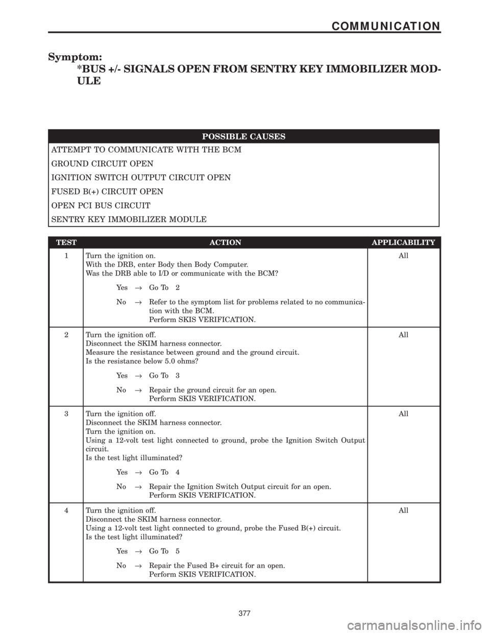
Symptom:
*BUS +/- SIGNALS OPEN FROM SENTRY KEY IMMOBILIZER MOD-
ULE
POSSIBLE CAUSES
ATTEMPT TO COMMUNICATE WITH THE BCM
GROUND CIRCUIT OPEN
IGNITION SWITCH OUTPUT CIRCUIT OPEN
FUSED B(+) CIRCUIT OPEN
OPEN PCI BUS CIRCUIT
SENTRY KEY IMMOBILIZER MODULE
TEST ACTION APPLICABILITY
1 Turn the ignition on.
With the DRB, enter Body then Body Computer.
Was the DRB able to I/D or communicate with the BCM?All
Ye s®Go To 2
No®Refer to the symptom list for problems related to no communica-
tion with the BCM.
Perform SKIS VERIFICATION.
2 Turn the ignition off.
Disconnect the SKIM harness connector.
Measure the resistance between ground and the ground circuit.
Is the resistance below 5.0 ohms?All
Ye s®Go To 3
No®Repair the ground circuit for an open.
Perform SKIS VERIFICATION.
3 Turn the ignition off.
Disconnect the SKIM harness connector.
Turn the ignition on.
Using a 12-volt test light connected to ground, probe the Ignition Switch Output
circuit.
Is the test light illuminated?All
Ye s®Go To 4
No®Repair the Ignition Switch Output circuit for an open.
Perform SKIS VERIFICATION.
4 Turn the ignition off.
Disconnect the SKIM harness connector.
Using a 12-volt test light connected to ground, probe the Fused B(+) circuit.
Is the test light illuminated?All
Ye s®Go To 5
No®Repair the Fused B+ circuit for an open.
Perform SKIS VERIFICATION.
377
COMMUNICATION
Page 407 of 4284
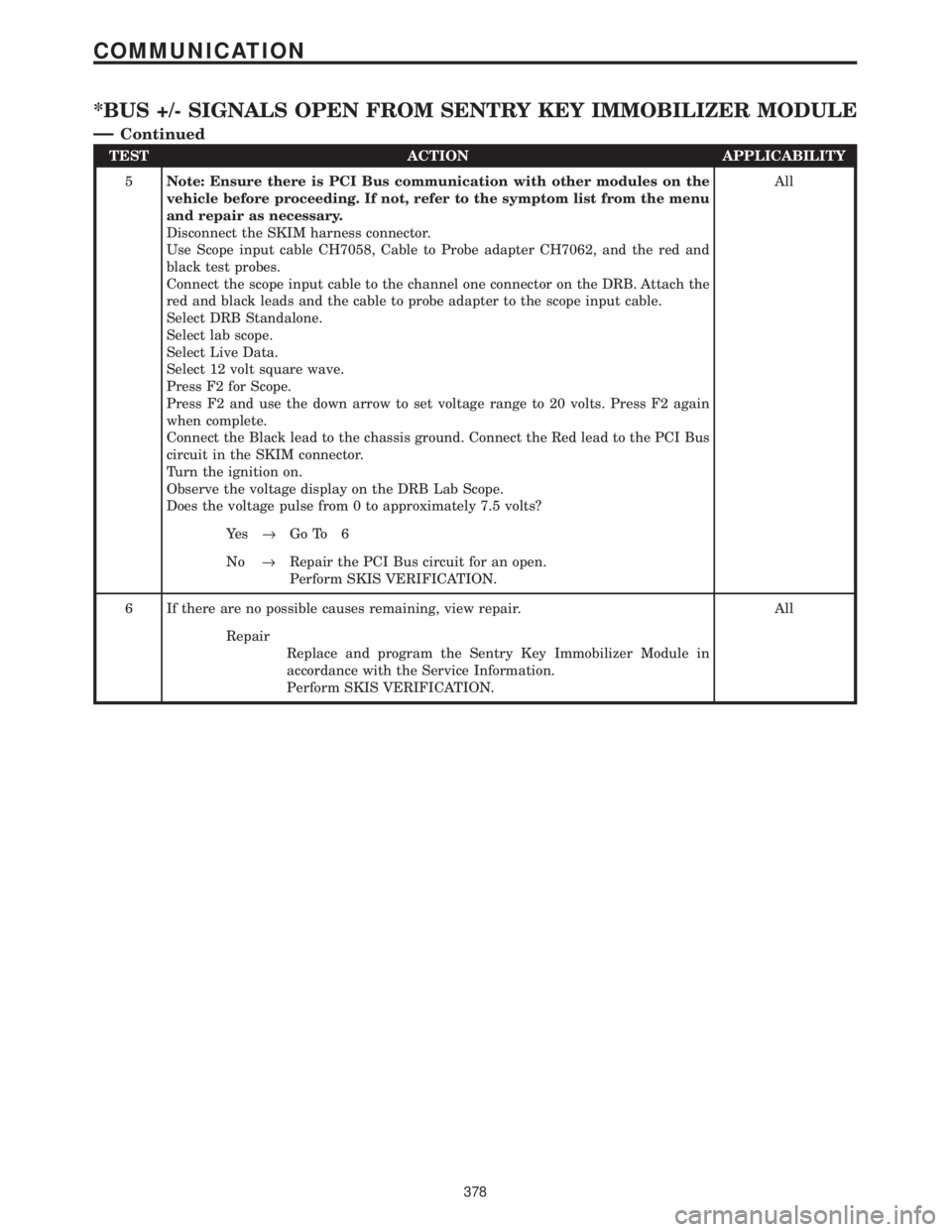
TEST ACTION APPLICABILITY
5Note: Ensure there is PCI Bus communication with other modules on the
vehicle before proceeding. If not, refer to the symptom list from the menu
and repair as necessary.
Disconnect the SKIM harness connector.
Use Scope input cable CH7058, Cable to Probe adapter CH7062, and the red and
black test probes.
Connect the scope input cable to the channel one connector on the DRB. Attach the
red and black leads and the cable to probe adapter to the scope input cable.
Select DRB Standalone.
Select lab scope.
Select Live Data.
Select 12 volt square wave.
Press F2 for Scope.
Press F2 and use the down arrow to set voltage range to 20 volts. Press F2 again
when complete.
Connect the Black lead to the chassis ground. Connect the Red lead to the PCI Bus
circuit in the SKIM connector.
Turn the ignition on.
Observe the voltage display on the DRB Lab Scope.
Does the voltage pulse from 0 to approximately 7.5 volts?All
Ye s®Go To 6
No®Repair the PCI Bus circuit for an open.
Perform SKIS VERIFICATION.
6 If there are no possible causes remaining, view repair. All
Repair
Replace and program the Sentry Key Immobilizer Module in
accordance with the Service Information.
Perform SKIS VERIFICATION.
378
COMMUNICATION
*BUS +/- SIGNALS OPEN FROM SENTRY KEY IMMOBILIZER MODULE
Ð
Continued
Page 601 of 4284
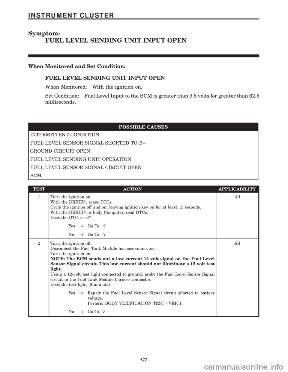
Symptom:
FUEL LEVEL SENDING UNIT INPUT OPEN
When Monitored and Set Condition:
FUEL LEVEL SENDING UNIT INPUT OPEN
When Monitored: With the ignition on.
Set Condition: Fuel Level Input to the BCM is greater than 9.8 volts for greater than 62.5
milliseconds.
POSSIBLE CAUSES
INTERMITTENT CONDITION
FUEL LEVEL SENSOR SIGNAL SHORTED TO B+
GROUND CIRCUIT OPEN
FUEL LEVEL SENDING UNIT OPERATION
FUEL LEVEL SENSOR SIGNAL CIRCUIT OPEN
BCM
TEST ACTION APPLICABILITY
1 Turn the ignition on.
With the DRBIIIt, erase DTCs.
Cycle the ignition off and on, leaving ignition key on for at least 15 seconds.
With the DRBIIItin Body Computer, read DTCs.
Does the DTC reset?All
Ye s®Go To 2
No®Go To 7
2 Turn the ignition off.
Disconnect the Fuel Tank Module harness connector.
Turn the ignition on.
NOTE: The BCM sends out a low current 12 volt signal on the Fuel Level
Sensor Signal circuit. This low current should not illuminate a 12 volt test
light.
Using a 12-volt test light connected to ground, probe the Fuel Level Sensor Signal
circuit in the Fuel Tank Module harness connector.
Does the test light illuminate?All
Ye s®Repair the Fuel Level Sensor Signal circuit shorted to battery
voltage.
Perform BODY VERIFICATION TEST - VER 1.
No®Go To 3
572
INSTRUMENT CLUSTER
Page 603 of 4284
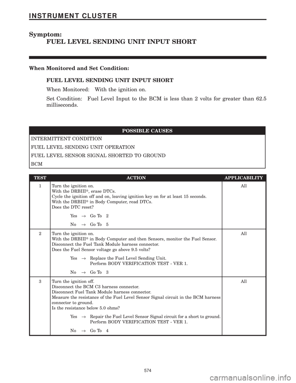
Symptom:
FUEL LEVEL SENDING UNIT INPUT SHORT
When Monitored and Set Condition:
FUEL LEVEL SENDING UNIT INPUT SHORT
When Monitored: With the ignition on.
Set Condition: Fuel Level Input to the BCM is less than 2 volts for greater than 62.5
milliseconds.
POSSIBLE CAUSES
INTERMITTENT CONDITION
FUEL LEVEL SENDING UNIT OPERATION
FUEL LEVEL SENSOR SIGNAL SHORTED TO GROUND
BCM
TEST ACTION APPLICABILITY
1 Turn the ignition on.
With the DRBIIIt, erase DTCs.
Cycle the ignition off and on, leaving ignition key on for at least 15 seconds.
With the DRBIIItin Body Computer, read DTCs.
Does the DTC reset?All
Ye s®Go To 2
No®Go To 5
2 Turn the ignition on.
With the DRBIIItin Body Computer and then Sensors, monitor the Fuel Sensor.
Disconnect the Fuel Tank Module harness connector.
Does the Fuel Sensor voltage go above 9.5 volts?All
Ye s®Replace the Fuel Level Sending Unit.
Perform BODY VERIFICATION TEST - VER 1.
No®Go To 3
3 Turn the ignition off.
Disconnect the BCM C3 harness connector.
Disconnect Fuel Tank Module harness connector.
Measure the resistance of the Fuel Level Sensor Signal circuit in the BCM harness
connector to ground.
Is the resistance below 5.0 ohms?All
Ye s®Repair the Fuel Level Sensor Signal circuit for a short to ground.
Perform BODY VERIFICATION TEST - VER 1.
No®Go To 4
574
INSTRUMENT CLUSTER
Page 605 of 4284

Symptom:
IOD WAKEUP CLUSTER OUTPUT OPEN
When Monitored and Set Condition:
IOD WAKEUP CLUSTER OUTPUT OPEN
When Monitored: With the ignition on.
Set Condition: The BCM is active and the Instrument Cluster does not responed on the
Instrument Cluster Wake Up Sense circuit.
POSSIBLE CAUSES
INTERMITTENT CONDITION
INSTRUMENT CLUSTER WAKE UP SENSE CKT OPEN
INSTRUMENT CLUSTER WAKE UP SENSE CKT SHORT TO GROUND
INSTRUMENT CLUSTER
BODY CONTROL MODULE
TEST ACTION APPLICABILITY
1 Turn the ignition on.
With the DRBIIIt, erase DTCs.
Cycle the ignition off and on several times, leaving ignition key on for at least 15
seconds.
With the DRBIIItin Body Computer, read DTCs.
Does the DTC reset?All
Ye s®Go To 2
No®Go To 5
2 Turn the ignition off.
Disconnect the BCM C4 harness connector.
Turn the ignition on.
Measure the voltage of the Instrument Cluster Wake Up Sense circuit in the BCM C4
harness connector.
Is the voltage above 10.0 volts?All
Ye s®Replace the Body Control Module.
Perform BODY VERIFICATION TEST - VER 1.
No®Go To 3
576
INSTRUMENT CLUSTER
Page 607 of 4284
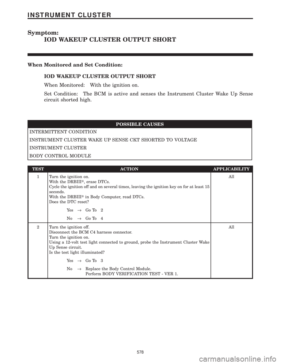
Symptom:
IOD WAKEUP CLUSTER OUTPUT SHORT
When Monitored and Set Condition:
IOD WAKEUP CLUSTER OUTPUT SHORT
When Monitored: With the ignition on.
Set Condition: The BCM is active and senses the Instrument Cluster Wake Up Sense
circuit shorted high.
POSSIBLE CAUSES
INTERMITTENT CONDITION
INSTRUMENT CLUSTER WAKE UP SENSE CKT SHORTED TO VOLTAGE
INSTRUMENT CLUSTER
BODY CONTROL MODULE
TEST ACTION APPLICABILITY
1 Turn the ignition on.
With the DRBIIIt, erase DTCs.
Cycle the ignition off and on several times, leaving the ignition key on for at least 15
seconds.
With the DRBIIItin Body Computer, read DTCs.
Does the DTC reset?All
Ye s®Go To 2
No®Go To 4
2 Turn the ignition off.
Disconnect the BCM C4 harness connector.
Turn the ignition on.
Using a 12-volt test light connected to ground, probe the Instrument Cluster Wake
Up Sense circuit.
Is the test light illuminated?All
Ye s®Go To 3
No®Replace the Body Control Module.
Perform BODY VERIFICATION TEST - VER 1.
578
INSTRUMENT CLUSTER