manual transmission CHRYSLER VOYAGER 2001 Owner's Guide
[x] Cancel search | Manufacturer: CHRYSLER, Model Year: 2001, Model line: VOYAGER, Model: CHRYSLER VOYAGER 2001Pages: 4284, PDF Size: 83.53 MB
Page 2445 of 4284
Component Page
Right Sliding Door Control Module C2
(Power Sliding Door).............. 8W-80-114
Right Sliding Door Latch Sensing Switch
(Power Sliding Door).............. 8W-80-114
Right Sliding Door Lock Motor
(Power Sliding Door).............. 8W-80-114
Right Sliding Door Lock Motor/
Ajar Switch (Manual Sliding Door) . . . 8W-80-115
Right Sliding Door Motor
(Power Sliding Door).............. 8W-80-115
Right Speed Control Switch.......... 8W-80-115
Right Stop/Turn Signal Relay
(Trailer Tow).................... 8W-80-115
Right Turn Signal Lamp
(Built-Up-Export)................ 8W-80-116
Right Visor/Vanity Lamp
(Premium/Luxury)................ 8W-80-116
Sentry Key Immobilizer Module....... 8W-80-116
Siren (United Kingdom)............. 8W-80-116
Solenoid/Pressure Switch Assy (EATX) . . 8W-80-117Component Page
Speed Control Servo (Gas)............ 8W-80-117
Speed Sensor-Input (EATX)........... 8W-80-117
Speed Sensor-Output (EATX)......... 8W-80-117
Thatcham Alarm Module C1
(United Kingdom)................ 8W-80-118
Thatcham Alarm Module C2
(United Kingdom)................ 8W-80-118
Throttle Position Sensor (Gas)......... 8W-80-118
Torque Converter Clutch Solenoid
(ATX).......................... 8W-80-118
Traction Control Switch.............. 8W-80-119
Trailer Tow Connector (Except
Built-Up-Export)................. 8W-80-119
Transmission Control Module (EATX) . . . 8W-80-119
Transmission Range Sensor (EATX).... 8W-80-120
TXV Solenoid (ATC)................ 8W-80-121
Vehicle Speed Sensor (MTX/ATX)...... 8W-80-121
Washer Fluid Level Switch........... 8W-80-121
Water In Fuel Sensor (Diesel)......... 8W-80-121
Wiper Module..................... 8W-80-121
RG8W-80 CONNECTOR PIN-OUTS8Wa-80-5
Page 2628 of 4284
the cylinder in question.The recommended com-
pression pressures are to be used only as a
guide to diagnosing engine problems. An engine
should not be disassembled to determine the
cause of low compression unless some malfunc-
tion is present.
DIAGNOSIS AND TESTING - ENGINE OIL LEAK
Begin with a thorough visual inspection of the
engine, particularly at the area of the suspected leak.
If an oil leak source is not readily identifiable, the
following steps should be followed:
(1) Do not clean or degrease the engine at this
time because some solvents may cause rubber to
swell, temporarily stopping the leak.
(2) Add an oil soluble dye (use as recommended by
manufacturer). Start the engine and let idle for
approximately 15 minutes. Check the oil dipstick to
make sure the dye is thoroughly mixed as indicated
with a bright yellow color under a black light.
(3) Using a black light, inspect the entire engine
for fluorescent dye, particularly at the suspected area
of oil leak. If the oil leak is found and identified,
repair as necessary.
(4) If dye is not observed, drive the vehicle at var-
ious speeds for approximately 24 km (15 miles), and
repeat inspection.
(5)If the oil leak source is not positively
identified at this time, proceed with the air leak
detection test method as follows:
²Disconnect the fresh air hose (make-up air) at
the cylinder head cover and plug or cap the nipple on
the cover.
²Remove the PCV valve hose from the cylinder
head cover. Cap or plug the PCV valve nipple on the
cover.
²Attach an air hose with pressure gauge and reg-
ulator to the dipstick tube.
CAUTION: Do not subject the engine assembly to
more than 20.6 kpa (3 PSI) of test pressure.
²Gradually apply air pressure from 1 psi to 2.5
psi maximum while applying soapy water at the sus-
pected source. Adjust the regulator to the suitable
test pressure that provides the best bubbles which
will pinpoint the leak source. If the oil leak is
detected and identified, repair per service manual
procedures.
²If the leakage occurs at the crankshaft rear oil
seal area, refer to the section, Inspection for Rear
Seal Area Leak.
(6) If no leaks are detected, turn off the air supply.
Remove the air hose, all plugs, and caps. Install the
PCV valve and fresh air hose (make-up air). Proceed
to next step.(7) Clean the oil off the suspect oil leak area using
a suitable solvent. Drive the vehicle at various
speeds approximately 24 km (15 miles). Inspect the
engine for signs of an oil leak by using a black light.
NOTE: If oil leakage is observed at the dipstick tube
to block location; remove the tube, clean and reseal
using MoparTStud & Bearing Mount (press fit tube
applications only), and for O-ring style tubes,
remove tube and replace the O-ring seal.
INSPECTION FOR REAR SEAL AREA LEAKS
Since it is sometimes difficult to determine the
source of an oil leak in the rear seal area of the
engine, a more involved inspection is necessary. The
following steps should be followed to help pinpoint
the source of the leak.
If the leakage occurs at the crankshaft rear oil seal
area:
(1) Disconnect the battery.
(2) Raise the vehicle.
(3) Remove torque converter or clutch housing
cover and inspect rear of block for evidence of oil.
Use a black light to check for the oil leak. If a leak is
present in this area, remove transmission for further
inspection.
(a) Circular spray pattern generally indicates
seal leakage or crankshaft damage.
(b) Where leakage tends to run straight down,
possible causes are a porous block, oil gallery cup
plug, bedplate to cylinder block mating surfaces
and seal bore. See proper repair procedures for
these items.
(4) If no leaks are detected, pressurize the crank-
case as previously described.
CAUTION: Do not exceed 20.6 kPa (3 psi).
(5) If the leak is not detected, very slowly turn the
crankshaft and watch for leakage. If a leak is
detected between the crankshaft and seal while
slowly turning the crankshaft, it is possible the
crankshaft seal surface is damaged. The seal area on
the crankshaft could have minor nicks or scratches
that can be polished out with emery cloth.
CAUTION: Use extreme caution when crankshaft
polishing is necessary to remove minor nicks and
scratches. The crankshaft seal flange is especially
machined to complement the function of the rear oil
seal.
(6) For bubbles that remain steady with shaft
rotation, no further inspection can be done until dis-
assembled.
9 - 4 ENGINE 2.4LRS
ENGINE 2.4L (Continued)
Page 2702 of 4284
²Gradually apply air pressure from 1 psi to 2.5
psi maximum while applying soapy water at the sus-
pected source. Adjust the regulator to the suitable
test pressure that provides the best bubbles which
will pinpoint the leak source. If the oil leak is
detected and identified, repair per service manual
procedures.
²If the leakage occurs at the crankshaft rear oil
seal area, refer to the section, Inspection for Rear
Seal Area Leak.
(6) If no leaks are detected, turn off the air supply.
Remove the air hose, all plugs, and caps. Install the
PCV valve and fresh air hose (make-up air). Proceed
to next step.
(7) Clean the oil off the suspect oil leak area using
a suitable solvent. Drive the vehicle at various
speeds approximately 24 km (15 miles). Inspect the
engine for signs of an oil leak by using a black light.
NOTE: If oil leakage is observed at the dipstick tube
to block location; remove the tube, clean and reseal
using MoparTStud & Bearing Mount (press fit tube
applications only), and for O-ring style tubes,
remove tube and replace the O-ring seal.
INSPECTION FOR REAR SEAL AREA LEAKS
Since it is sometimes difficult to determine the
source of an oil leak in the rear seal area of the
engine, a more involved inspection is necessary. The
following steps should be followed to help pinpoint
the source of the leak.
If the leakage occurs at the crankshaft rear oil seal
area:
(1) Disconnect the battery.
(2) Raise the vehicle.
(3) Remove torque converter or clutch housing
cover and inspect rear of block for evidence of oil.
Use a black light to check for the oil leak. If a leak is
present in this area, remove transmission for further
inspection.
(a) Circular spray pattern generally indicates
seal leakage or crankshaft damage.
(b) Where leakage tends to run straight down,
possible causes are a porous block, oil gallery cup
plug, bedplate to cylinder block mating surfaces
and seal bore. See proper repair procedures for
these items.
(4) If no leaks are detected, pressurize the crank-
case as previously described.
CAUTION: Do not exceed 20.6 kPa (3 psi).
(5) If the leak is not detected, very slowly turn the
crankshaft and watch for leakage. If a leak is
detected between the crankshaft and seal while
slowly turning the crankshaft, it is possible thecrankshaft seal surface is damaged. The seal area on
the crankshaft could have minor nicks or scratches
that can be polished out with emery cloth.
CAUTION: Use extreme caution when crankshaft
polishing is necessary to remove minor nicks and
scratches. The crankshaft seal flange is especially
machined to complement the function of the rear oil
seal.
(6) For bubbles that remain steady with shaft
rotation, no further inspection can be done until dis-
assembled.
(7) After the oil leak root cause and appropriate
corrective action have been identified, replace compo-
nent(s) as necessary.
DIAGNOSIS AND TESTING - CYLINDER
COMPRESSION PRESSURE
The results of a cylinder compression pressure test
can be utilized to diagnose several engine malfunc-
tions.
Ensure the battery is completely charged and the
engine starter motor is in good operating condition.
Otherwise the indicated compression pressures may
not be valid for diagnosis purposes.
(1) Check engine oil level and add oil if necessary.
(2) Drive the vehicle until engine reaches normal
operating temperature. Select a route free from traf-
fic and other forms of congestion, observe all traffic
laws, and accelerate through the gears several times
briskly.
(3) Remove all spark plugs from engine. As spark
plugs are being removed, check electrodes for abnor-
mal firing indicators fouled, hot, oily, etc. Record cyl-
inder number of spark plug for future reference.
(4) Disconnect the ignition coil electrical connector.
(5) Be sure throttle blade is fully open during the
compression check.
(6) Insert compression gage adaptor Special Tool
8116 or the equivalent, into the #1 spark plug hole in
cylinder head. Connect the 0±500 psi (Blue) pressure
transducer with cable adaptors to the DRBIIIt.
(7) Crank engine until maximum pressure is
reached on gage. Record this pressure as #1 cylinder
pressure.
(8) Repeat the previous step for all remaining cyl-
inders.
(9) Compression should not be less than 689 kPa
(100 psi) and not vary more than 25 percent from cyl-
inder to cylinder.
(10) If one or more cylinders have abnormally low
compression pressures, repeat the compression test.
(11) If the same cylinder or cylinders repeat an
abnormally low reading on the second compression
test, it could indicate the existence of a problem in
9 - 78 ENGINE 3.3/3.8LRS
ENGINE 3.3/3.8L (Continued)
Page 2789 of 4284
(7) Attach front engine mount bracket to lower
radiator support. Torque to 54N´m (40 ft. lbs.)
(8) Connect cabin heater coolant hose.
(9) Connect exhaust pipe to the turbocharger
downpipe flange. Torque to 28 N´m (250 in. lbs.)
(10) Connect reverse lamp electrical connector at
transmission.
(11) Connect both shifter cables (Refer to 21 -
TRANSMISSION/TRANSAXLE/MANUAL/GEAR
SHIFT CABLE - INSTALLATION).
(12) Connect the clutch slave cylinder quick dis-
connect connector (RHD only)(Refer to 6 - CLUTCH/
SLAVE CYLINDER - INSTALLATION).
(13) Install engine harness into bracket on trans-
mission.
(14) Lower vehicle.
(15) Connect fuel supply and return lines.
(16) Connect A/C lines to A/C compressor. Torque
to 23N´m (17 ft. lbs.)
(17) Route engine wiring harnes to proper location.
(18) Connect engine harness ground cables to
engine block
(19) Connect starter solenoid electrical connector
and battery feed wire to starter. Torque to 10N´m (90
in. lbs.)
(20) Connect A/C compressor, injection pump, glow
plugs, and coolant temperature sensor electrical con-
nectors.
(21) Connect generator electrical connector. Torque
to 9N´m (75 in. lbs.)
(22) Connect the fuel injector, fuel pressure sensor,
boost pressure/intake air temp sensor, cam sensor,
and egr solenoid electrical connectors (Fig. 9).
(23) Connect egr solenoid vacuum supply line to
brake boost vacuum supply line.
(24) Connect brake booster vacuum supply line.
(25) Connect heater core return hose to coolant
pipe.
(26) Connect lower radiator hose to engine (Fig. 8).
(27) Install charger air cooler inlet hose (Fig. 7).
(28) Install charge air cooler outlet hose (Fig. 7).
(29) Connect upper radiator hose to engine (Fig.
8).
(30) Install battery shield.
(31) Install coolant reserve pressure container
(Refer to 7 - COOLING/ENGINE/COOLANT RECOV-
ERY PRESS CONTAINER - INSTALLATION).
(32) Install power steering reservoir and bracket
(Fig. 5).
(33) Raise vehicle
(34) Connect oil pressure sensor, oil temperature
sensor, engine speed sensor, and vehicle speed sensor
electrical connector (Fig. 10).(35) Install suspension cradle in vehicle (Refer to
13 - FRAME & BUMPERS/FRAME/ENGINE CRA-
DLE CROSSMEMBER - INSTALLATION).
(36) Install both axle shaft assemblies (Refer to 3 -
DIFFERENTIAL & DRIVELINE/HALF SHAFT -
INSTALLATION).
(37) Connect the power steering supply, pressure,
and return lines to power steering pump (Fig. 5).
(38) Install the power steering line brackets on oil
pan (Fig. 5).
(39) Install lower splash shield and side panels.
(40) Install both front wheel and tire assemblies.
(41) Lower vehicle.
(42) Install air cleaner housing, MAF sensor, and
air intake tube assembly (Fig. 4).
(43) Refill transmission to proper level (Refer to 21
- TRANSMISSION/TRANSAXLE/MANUAL/FLUID -
STANDARD PROCEDURE).
(44) Refill engine coolant (Refer to 7 - COOLING/
ENGINE/COOLANT - STANDARD PROCEDURE).
(45) Recharge A/C system (Refer to 24 - HEATING
& AIR CONDITIONING/PLUMBING/REFRIGER-
ANT - STANDARD PROCEDURE) .
(46) Install engine cover (Refer to 9 - ENGINE -
INSTALLATION) (Fig. 3).
(47) Connect negative battery cable.
INSTALLATION - ENGINE COVER
(1) Install engine cover on engine.
(2) Install the engine cover mounting bolts (Fig.
11).
SPECIFICATIONS
SPECIFICATIONS - 2.5L COMMON RAIL
DIESEL ENGINE
ENGINE SPECIFICATIONS
DESCRIPTION SPECIFICATION
Type R2516C
Number of Cylinders 4
Bore 92 mm
Stroke 94 mm
Displacement 2499.5cc
Injection Order 1-3-4-2
Compression Ratio 17.5:1 ( 0.5)
Maximum Power 103kW (140 HP) @ 4000
RPM
Peak Torque 340Nm (34.6 kgm) @
1800 RPM
RGENGINE 2.5L TURBO DIESEL9a-7
ENGINE 2.5L TURBO DIESEL (Continued)
Page 2848 of 4284

DIAGNOSIS AND TESTING - EXHAUST SYSTEM
CONDITION POSSIBLE CAUSES CORRECTION
EXCESSIVE EXHAUST NOISE
(UNDER HOOD)1. Exhaust manifold cracked or
broken.1. Replace manifold.
2. Manifold to cylinder head leak. 2. Tighten manifold and/or replace
gasket.
3. EGR Valve to manifold gasket
leakage.3. Tighten fasteners or replace
gasket.
4. EGR Valve to EGR tube gasket
leakage.4. Tighten fasteners or replace
gasket.
5. EGR tube to manifold tube
leakage.5. Tighten tube nut.
6. Exhaust flex-joint to manifold
leak.6. Tighten joint fasteners and/or
replace gasket.
7. Exhaust flex-joint. 7. Replace catalytic converter
assembly.
8. Pipe and shell noise from front
exhaust pipe.8. Characteristic of single wall pipe.
EXCESSIVE EXHAUST NOISE 1. Leak at exhaust pipe joints. 1. Tighten clamps at leaking joints.
2. Burned or rusted out muffler
assembly or exhaust pipe.2. Replace muffler resonator tailpipe
assembly or exhaust pipe with
catalytic converter assembly.
3. Burned or rusted out resonator. 3. Replace muffler resonator tailpipe
assembly.
4. Restriction in exhaust system. 4. Perform exhaust restriction test.
replace component as necessary.
5. Converter material in muffler. 5. Replace muffler and converter
assemblies. Check fuel injection and
ignition systems for proper
operation.
DIAGNOSIS AND TESTING - EXHAUST SYSTEM
RESTRICTION
Exhaust system restriction can be checked by mea-
suring back pressure using the DRB IIItand PEP
module pressure tester.
WARNING: THE NORMAL OPERATING TEMPERA-
TURE OF THE EXHAUST SYSTEM IS VERY HIGH.
THEREFORE, NEVER WORK AROUND OR ATTEMPT
TO SERVICE ANY PART OF THE EXHAUST SYSTEM
UNTIL IT IS COOLED. SPECIAL CARE SHOULD BE
TAKEN WHEN WORKING NEAR THE CATALYTIC
CONVERTER. THE TEMPERATURE OF THE CON-
VERTER RISES TO A HIGH LEVEL AFTER A SHORT
PERIOD OF ENGINE OPERATION TIME.
(1) Disconnect and remove the upstream (before
catalytic converter) oxygen sensor. (Refer to 14 -FUEL SYSTEM/FUEL INJECTION/O2 SENSOR -
REMOVAL)
(2) Install the Exhaust Back Pressure Fitting
Adaptor CH8519.
(3) Connect the Low Pressure Sensor (15 psi)
CH7063 to the back pressure fitting.
(4) Following the PEP module instruction manual,
connect all required cables to the DRB IIItand PEP
module. Select the available menu options on the
DRBIIItdisplay screen for using the digital pressure
gauge function.
(5) Apply the park brake and start the engine.
(6) With transmission in Park or Neutral, raise
engine speed to 2000 RPM. Monitor the pressure
readings on the DRBIIIt. Back pressure should not
exceed specified limit. Refer to specification in table
below EXHAUST BACK PRESSURE LIMITS .
11 - 2 EXHAUST SYSTEMRS
EXHAUST SYSTEM (Continued)
Page 2942 of 4284
ing gear. This travel pushes and pulls the tie rods to
change the direction of the vehicle's front wheels.
Power assist steering provided by the power steer-
ing pump is controlled by an open center, rotary type
control valve which directs oil from the pump to
either side of the integral rack piston upon demand.
Road feel is controlled by the diameter of a torsion
bar which initially steers the vehicle. As required
steering effort increases, as in a turn, the torsion bar
twists, causing relative rotary motion between the
rotary valve body and the valve spool. This move-
ment directs oil behind the integral rack piston
which, in turn, builds up hydraulic pressure and
assists in the turning effort.
Manual steering control of the vehicle can be main-
tained if power steering assist is lost. However,
under this condition, steering effort is significantly
increased.
SERVICE WARNINGS AND CAUTIONS
WARNING: POWER STEERING FLUID, ENGINE
PARTS AND EXHAUST SYSTEM MAY BE
EXTREMELY HOT IF ENGINE HAS BEEN RUNNING.
DO NOT START ENGINE WITH ANY LOOSE OR DIS-
CONNECTED HOSES. DO NOT ALLOW HOSES TO
TOUCH HOT EXHAUST MANIFOLD OR CATALYST.
WARNING: FLUID LEVEL SHOULD BE CHECKED
WITH THE ENGINE OFF TO PREVENT PERSONAL
INJURY FROM MOVING PARTS.
CAUTION: When the system is open, cap all open
ends of the hoses, power steering pump fittings or
power steering gear ports to prevent entry of for-
eign material into the components.
REMOVAL - GEAR
CAUTION: Positioning the steering column in the
locked position will prevent the clockspring from
being accidentally over-extended when the steering
column is disconnected from the intermediate
steering coupler.
(1) Remove cap from power steering fluid reser-
voir.
(2) Using a siphon pump, remove as much fluid as
possible from the power steering fluid reservoir.
(3) With the ignition key in the locked position
turn the steering wheel to the left until the steering
wheel is in the locked position.
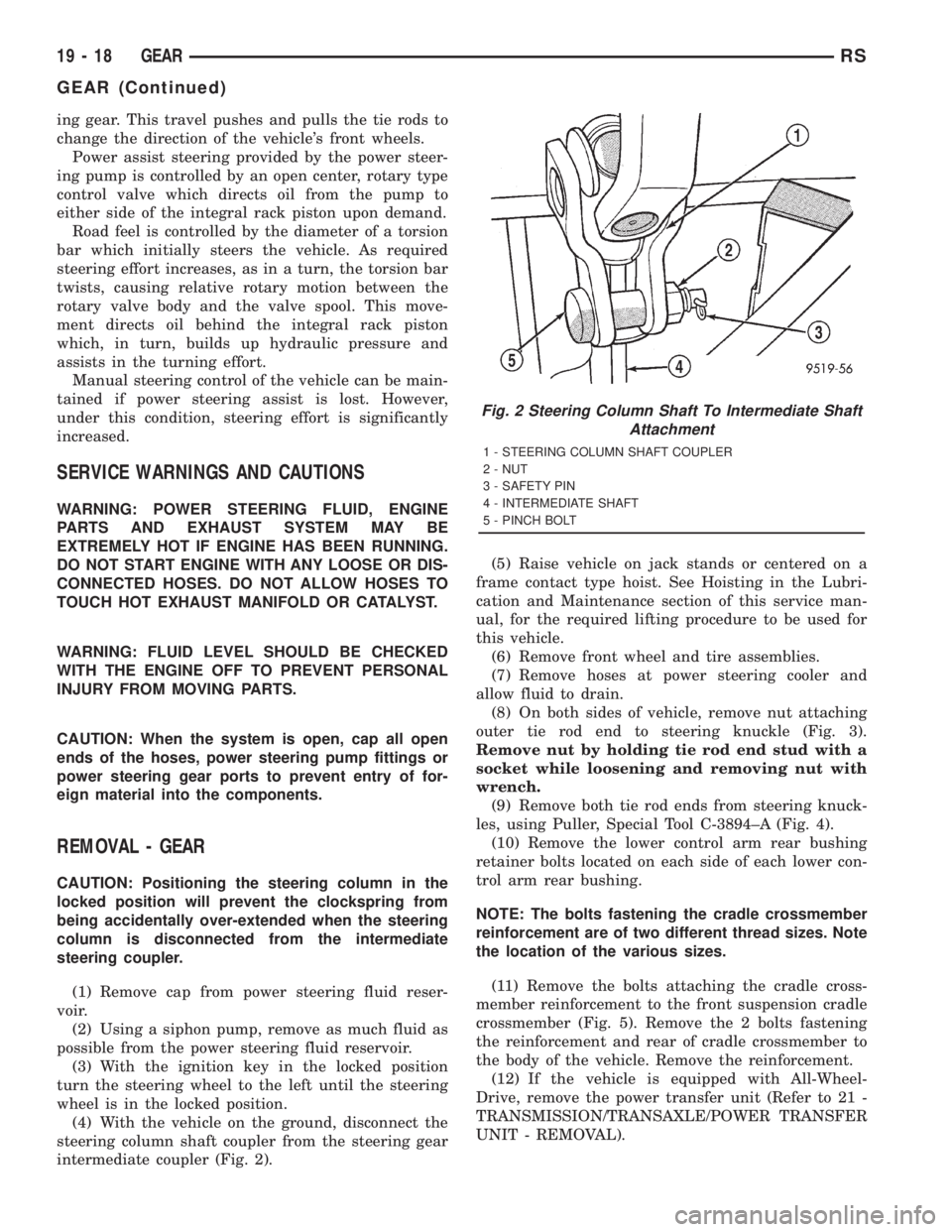
(4) With the vehicle on the ground, disconnect the
steering column shaft coupler from the steering gear
intermediate coupler (Fig. 2).(5) Raise vehicle on jack stands or centered on a
frame contact type hoist. See Hoisting in the Lubri-
cation and Maintenance section of this service man-
ual, for the required lifting procedure to be used for
this vehicle.
(6) Remove front wheel and tire assemblies.
(7) Remove hoses at power steering cooler and
allow fluid to drain.
(8) On both sides of vehicle, remove nut attaching
outer tie rod end to steering knuckle (Fig. 3).
Remove nut by holding tie rod end stud with a
socket while loosening and removing nut with
wrench.
(9) Remove both tie rod ends from steering knuck-
les, using Puller, Special Tool C-3894±A (Fig. 4).
(10) Remove the lower control arm rear bushing
retainer bolts located on each side of each lower con-
trol arm rear bushing.
NOTE: The bolts fastening the cradle crossmember
reinforcement are of two different thread sizes. Note
the location of the various sizes.
(11) Remove the bolts attaching the cradle cross-
member reinforcement to the front suspension cradle
crossmember (Fig. 5). Remove the 2 bolts fastening
the reinforcement and rear of cradle crossmember to
the body of the vehicle. Remove the reinforcement.
(12) If the vehicle is equipped with All-Wheel-
Drive, remove the power transfer unit (Refer to 21 -
TRANSMISSION/TRANSAXLE/POWER TRANSFER
UNIT - REMOVAL).
Fig. 2 Steering Column Shaft To Intermediate Shaft
Attachment
1 - STEERING COLUMN SHAFT COUPLER
2 - NUT
3 - SAFETY PIN
4 - INTERMEDIATE SHAFT
5 - PINCH BOLT
19 - 18 GEARRS
GEAR (Continued)
Page 2988 of 4284
OPERATION
Transmission output is directed to an integral dif-
ferential by a transfer gear system in the following
input-to-output ratios:
FIRST 2.69:1
SECOND 1.55:1
THIRD 1.00:1
REVERSE 2.10:1
DIAGNOSIS AND TESTING - PRELIMINARY
DIAGNOSIS
Automatic transaxle malfunctions are usually
caused by the following general conditions:
²Improper fluid level/condition
²Poor engine performance
²Improper engine or transaxle adjustments
²Transaxle hydraulic malfunctions²Transaxle mechanical malfunctions
Diagnosis of transaxle problems should always
begin with checking the easily accessible variables:
²Fluid level and condition
²Gearshift cable adjustment
²Throttle valve cable adjustment
After verifying or adjusting these variables, road
test the vehicle to determine if the problem has been
corrected or that further diagnosis is necessary. If the
problem still exists, refer to the following diagnosis
charts to aid in determining the source or cause of
failure.
Hydraulic pressure tests should be performed
when a transaxle internal failure is suspected. The
hydraulic flow charts, in the Schematics and Dia-
grams section of this group, outline fluid flow and
hydraulic circuitry. Circuit operation is provided for
all gear ranges. Normal working pressures are also
supplied for each of the gear ranges.
TRANSAXLE DIAGNOSIS CHARTS
CONDITION POSSIBLE CAUSES CORRECTION
HARSH ENGAGEMENT
(FROM NEUTRAL TO
DRIVE OR REVERSE)1. Fluid Level Low 1. Add Fluid
2. Throttle Linkage Misadjusted 2. Adjust linkage - setting may be too
long.
3. Excessive Pinion Backlash 3. Check per Service Manual. Correct as
needed.
4. Hydraulic Pressure Incorrect 4. Check pressure. Remove, overhaul or
adjust valve body as needed.
5. Band Misadjusted. 5. Adjust rear band.
6. Valve Body Check Balls Missing. 6. Inspect valve body for proper check
ball installation.
7. Clutch, band or planetary component
Damaged.7. Remove, disassemble and repair
transmission as necessary.
8. Converter Clutch (if equipped) Faulty. 8. Replace converter and flush cooler and
line before installing new converter.
21 - 24 AUTOMATIC - 31THRS
AUTOMATIC - 31TH (Continued)
Page 3043 of 4284
BANDS
KICKDOWN (FRONT) BAND
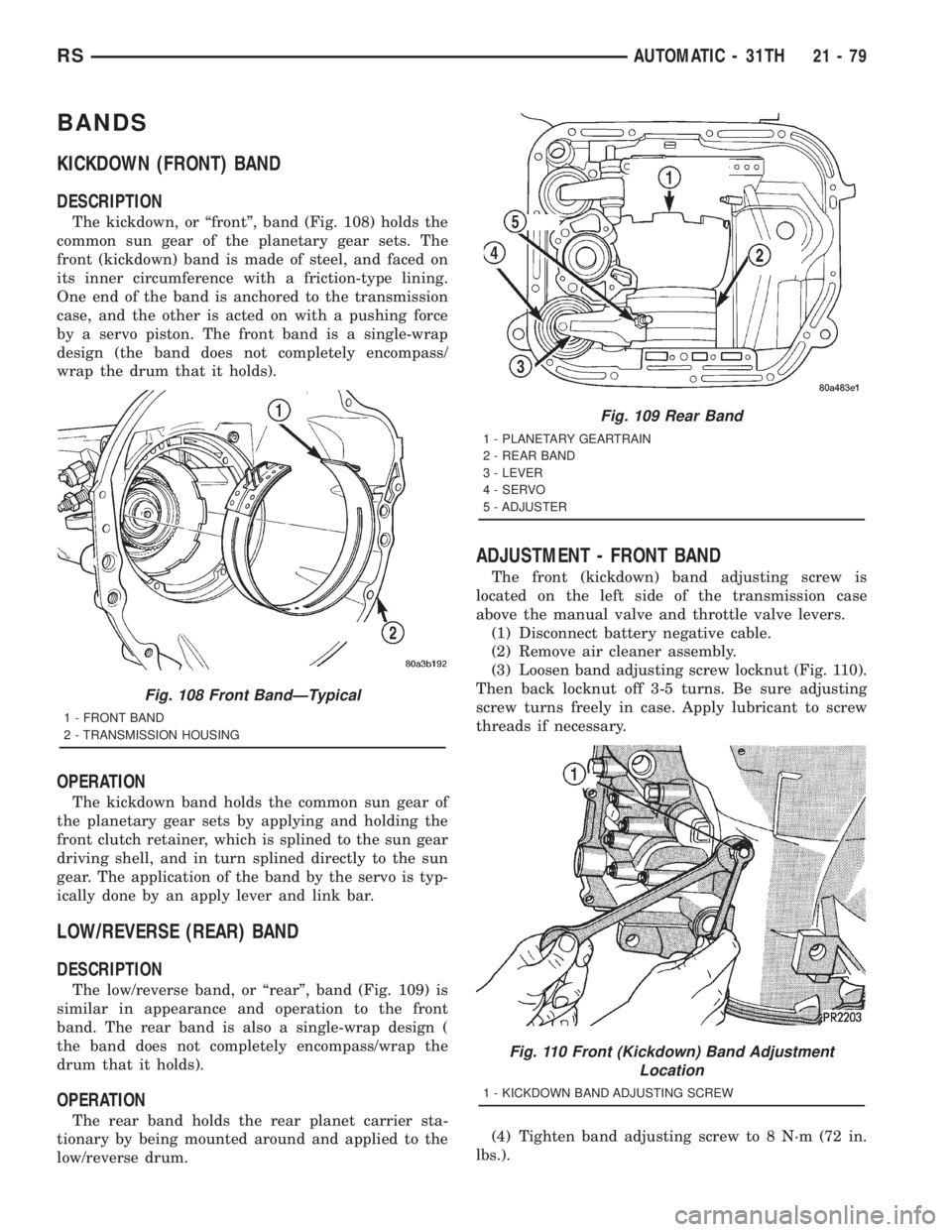
DESCRIPTION
The kickdown, or ªfrontº, band (Fig. 108) holds the
common sun gear of the planetary gear sets. The
front (kickdown) band is made of steel, and faced on
its inner circumference with a friction-type lining.
One end of the band is anchored to the transmission
case, and the other is acted on with a pushing force
by a servo piston. The front band is a single-wrap
design (the band does not completely encompass/
wrap the drum that it holds).
OPERATION
The kickdown band holds the common sun gear of
the planetary gear sets by applying and holding the
front clutch retainer, which is splined to the sun gear
driving shell, and in turn splined directly to the sun
gear. The application of the band by the servo is typ-
ically done by an apply lever and link bar.
LOW/REVERSE (REAR) BAND
DESCRIPTION
The low/reverse band, or ªrearº, band (Fig. 109) is
similar in appearance and operation to the front
band. The rear band is also a single-wrap design (
the band does not completely encompass/wrap the
drum that it holds).
OPERATION
The rear band holds the rear planet carrier sta-
tionary by being mounted around and applied to the
low/reverse drum.
ADJUSTMENT - FRONT BAND
The front (kickdown) band adjusting screw is
located on the left side of the transmission case
above the manual valve and throttle valve levers.
(1) Disconnect battery negative cable.
(2) Remove air cleaner assembly.
(3) Loosen band adjusting screw locknut (Fig. 110).
Then back locknut off 3-5 turns. Be sure adjusting
screw turns freely in case. Apply lubricant to screw
threads if necessary.
(4) Tighten band adjusting screw to 8 N´m (72 in.
lbs.).
Fig. 108 Front BandÐTypical
1 - FRONT BAND
2 - TRANSMISSION HOUSING
Fig. 109 Rear Band
1 - PLANETARY GEARTRAIN
2 - REAR BAND
3 - LEVER
4 - SERVO
5 - ADJUSTER
Fig. 110 Front (Kickdown) Band Adjustment
Location
1 - KICKDOWN BAND ADJUSTING SCREW
RSAUTOMATIC - 31TH21-79
Page 3064 of 4284
applied, move selector lever momentarily to each
position, ending in the park or neutral position.
(8) Check the transaxle fluid level and add an
appropriate amount to bring the transaxle fluid level
to 3mm (1/8 in.) below the ªADDº mark on the dip-
stick (Fig. 168).
(9) Recheck the fluid level after the transaxle has
reached normal operating temperature (180ÉF.).
(Refer to 21 - TRANSMISSION/TRANSAXLE/AUTO-
MATIC - 31TH/FLUID - STANDARD PROCEDURE)
(10) To prevent dirt from entering transaxle, make
certain that dipstick is fully seated into the dipstick
opening.
GEAR SHIFT CABLE
REMOVAL
(1) Disconnect battery negative cable.
(2) Disconnect gear shift cable at manual valve
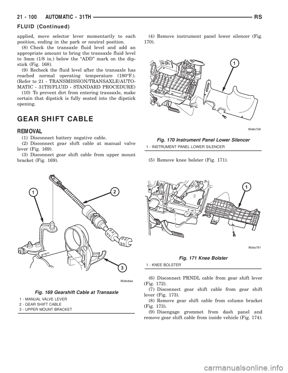
lever (Fig. 169).
(3) Disconnect gear shift cable from upper mount
bracket (Fig. 169).(4) Remove instrument panel lower silencer (Fig.
170).
(5) Remove knee bolster (Fig. 171).
(6) Disconnect PRNDL cable from gear shift lever
(Fig. 172).
(7) Disconnect gear shift cable from gear shift
lever (Fig. 173).
(8) Remove gear shift cable from column bracket
(Fig. 173).
(9) Disengage grommet from dash panel and
remove gear shift cable from inside vehicle (Fig. 174).
Fig. 169 Gearshift Cable at Transaxle
1 - MANUAL VALVE LEVER
2 - GEAR SHIFT CABLE
3 - UPPER MOUNT BRACKET
Fig. 170 Instrument Panel Lower Silencer
1 - INSTRUMENT PANEL LOWER SILENCER
Fig. 171 Knee Bolster
1 - KNEE BOLSTER
21 - 100 AUTOMATIC - 31THRS
FLUID (Continued)
Page 3067 of 4284
GEARSHIFT CABLE ADJUSTMENT
Lift and rotate the gearshift hand lever into the
park (P) gate position and remove the ignition key.
This confirms the shift lever is in the gated park (P)
position.
After confirming the park gate position, turn the
ignition switch . If the starter will operate, the park
gate position is correct. Move the shift lever into the
neutral (N) position. If the starter will operate in this
position, the linkage is properly adjusted. If the
starter fails to operate in either position, linkage
adjustment is required.
(1) Park the vehicle on level ground and set the
parking brake.
(2) Place the gearshift lever in park (P) gate posi-
tion and remove key.
(3) Loosen the cable adjustment screw at the
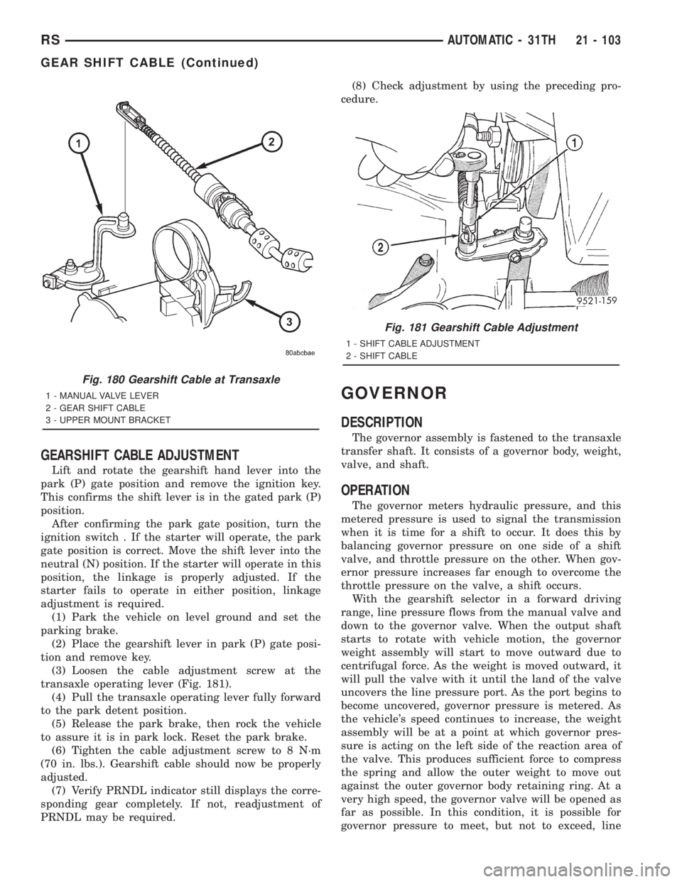
transaxle operating lever (Fig. 181).
(4) Pull the transaxle operating lever fully forward
to the park detent position.
(5) Release the park brake, then rock the vehicle
to assure it is in park lock. Reset the park brake.
(6) Tighten the cable adjustment screw to 8 N´m
(70 in. lbs.). Gearshift cable should now be properly
adjusted.
(7) Verify PRNDL indicator still displays the corre-
sponding gear completely. If not, readjustment of
PRNDL may be required.(8) Check adjustment by using the preceding pro-
cedure.
GOVERNOR
DESCRIPTION
The governor assembly is fastened to the transaxle
transfer shaft. It consists of a governor body, weight,
valve, and shaft.
OPERATION
The governor meters hydraulic pressure, and this
metered pressure is used to signal the transmission
when it is time for a shift to occur. It does this by
balancing governor pressure on one side of a shift
valve, and throttle pressure on the other. When gov-
ernor pressure increases far enough to overcome the
throttle pressure on the valve, a shift occurs.
With the gearshift selector in a forward driving
range, line pressure flows from the manual valve and
down to the governor valve. When the output shaft
starts to rotate with vehicle motion, the governor
weight assembly will start to move outward due to
centrifugal force. As the weight is moved outward, it
will pull the valve with it until the land of the valve
uncovers the line pressure port. As the port begins to
become uncovered, governor pressure is metered. As
the vehicle's speed continues to increase, the weight
assembly will be at a point at which governor pres-
sure is acting on the left side of the reaction area of
the valve. This produces sufficient force to compress
the spring and allow the outer weight to move out
against the outer governor body retaining ring. At a
very high speed, the governor valve will be opened as
far as possible. In this condition, it is possible for
governor pressure to meet, but not to exceed, line
Fig. 180 Gearshift Cable at Transaxle
1 - MANUAL VALVE LEVER
2 - GEAR SHIFT CABLE
3 - UPPER MOUNT BRACKET
Fig. 181 Gearshift Cable Adjustment
1 - SHIFT CABLE ADJUSTMENT
2 - SHIFT CABLE
RSAUTOMATIC - 31TH21 - 103
GEAR SHIFT CABLE (Continued)