rear view CHRYSLER VOYAGER 2001 Owner's Guide
[x] Cancel search | Manufacturer: CHRYSLER, Model Year: 2001, Model line: VOYAGER, Model: CHRYSLER VOYAGER 2001Pages: 4284, PDF Size: 83.53 MB
Page 1514 of 4284
JUMP STARTING
STANDARD PROCEDURE - JUMP STARTING
(1) Raise hood on disabled vehicle and visually
inspect engine compartment for:
²Battery cable clamp condition, clean if necessary.
²Frozen battery.
²Yellow or bright color test indicator, if equipped.
²Low battery fluid level.
²Generator drive belt condition and tension.
²Fuel fumes or leakage, correct if necessary.
CAUTION: If the cause of starting problem on dis-
abled vehicle is severe, damage to booster vehicle
charging system can result.
(2) When using another vehicle as a booster
source, park the booster vehicle within cable reach.
Turn off all accessories, set the parking brake, place
the automatic transmission in PARK or the manual
transmission in NEUTRAL and turn the ignition
OFF.
(3)
On disabled vehicle, place gear selector in park
or neutral and set park brake. Turn off all accessories.
(4) Connect jumper cables to booster battery. RED
clamp to positive terminal (+). BLACK clamp to neg-
ative terminal (-). DO NOT allow clamps at opposite
end of cables to touch, electrical arc will result.
Review all warnings in this procedure.
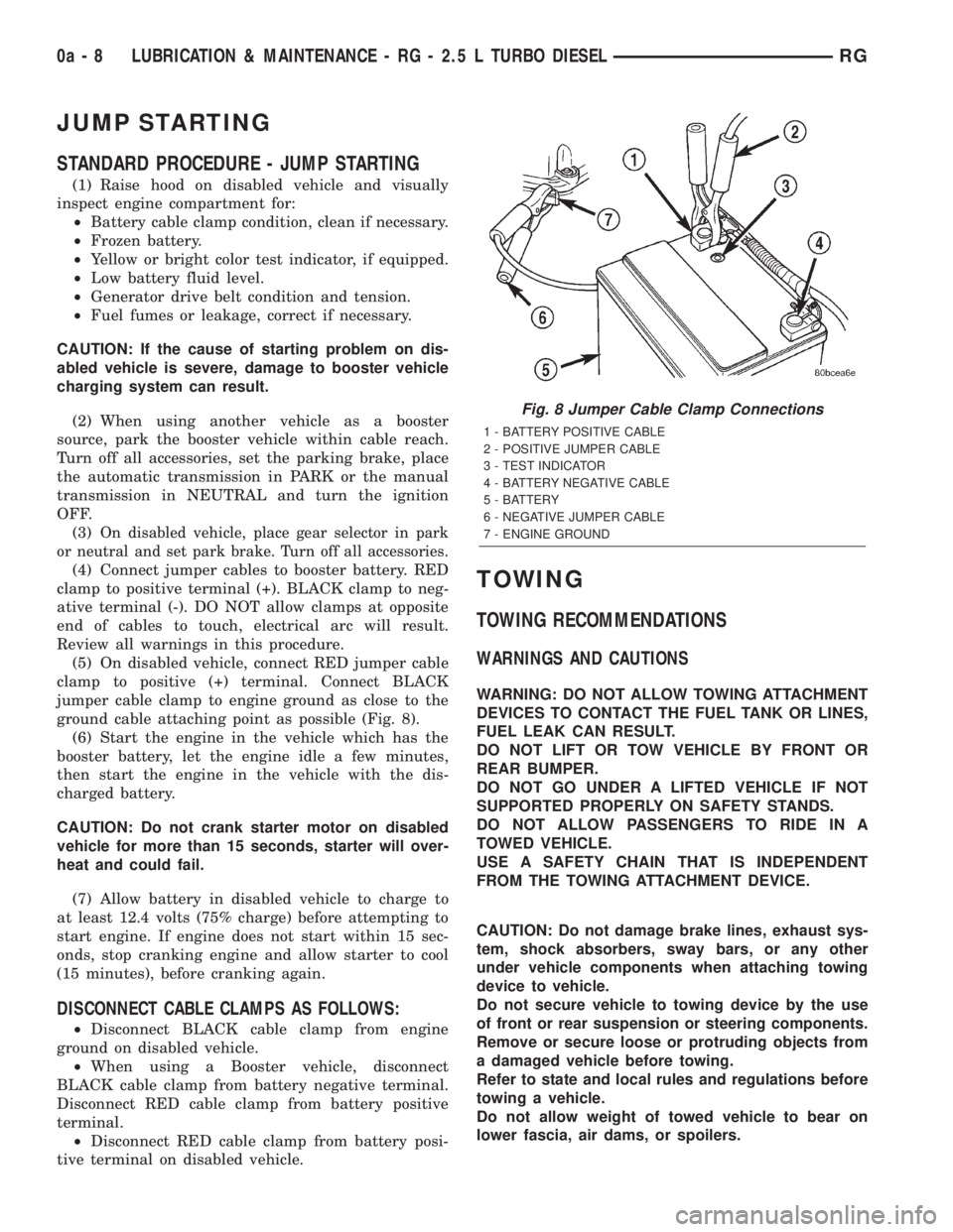
(5) On disabled vehicle, connect RED jumper cable
clamp to positive (+) terminal. Connect BLACK
jumper cable clamp to engine ground as close to the
ground cable attaching point as possible (Fig. 8).
(6) Start the engine in the vehicle which has the
booster battery, let the engine idle a few minutes,
then start the engine in the vehicle with the dis-
charged battery.
CAUTION: Do not crank starter motor on disabled
vehicle for more than 15 seconds, starter will over-
heat and could fail.
(7) Allow battery in disabled vehicle to charge to
at least 12.4 volts (75% charge) before attempting to
start engine. If engine does not start within 15 sec-
onds, stop cranking engine and allow starter to cool
(15 minutes), before cranking again.
DISCONNECT CABLE CLAMPS AS FOLLOWS:
²Disconnect BLACK cable clamp from engine
ground on disabled vehicle.
²When using a Booster vehicle, disconnect
BLACK cable clamp from battery negative terminal.
Disconnect RED cable clamp from battery positive
terminal.
²Disconnect RED cable clamp from battery posi-
tive terminal on disabled vehicle.
TOWING
TOWING RECOMMENDATIONS
WARNINGS AND CAUTIONS
WARNING: DO NOT ALLOW TOWING ATTACHMENT
DEVICES TO CONTACT THE FUEL TANK OR LINES,
FUEL LEAK CAN RESULT.
DO NOT LIFT OR TOW VEHICLE BY FRONT OR
REAR BUMPER.
DO NOT GO UNDER A LIFTED VEHICLE IF NOT
SUPPORTED PROPERLY ON SAFETY STANDS.
DO NOT ALLOW PASSENGERS TO RIDE IN A
TOWED VEHICLE.
USE A SAFETY CHAIN THAT IS INDEPENDENT
FROM THE TOWING ATTACHMENT DEVICE.
CAUTION: Do not damage brake lines, exhaust sys-
tem, shock absorbers, sway bars, or any other
under vehicle components when attaching towing
device to vehicle.
Do not secure vehicle to towing device by the use
of front or rear suspension or steering components.
Remove or secure loose or protruding objects from
a damaged vehicle before towing.
Refer to state and local rules and regulations before
towing a vehicle.
Do not allow weight of towed vehicle to bear on
lower fascia, air dams, or spoilers.
Fig. 8 Jumper Cable Clamp Connections
1 - BATTERY POSITIVE CABLE
2 - POSITIVE JUMPER CABLE
3 - TEST INDICATOR
4 - BATTERY NEGATIVE CABLE
5 - BATTERY
6 - NEGATIVE JUMPER CABLE
7 - ENGINE GROUND
0a - 8 LUBRICATION & MAINTENANCE - RG - 2.5 L TURBO DIESELRG
Page 1563 of 4284
CASTER
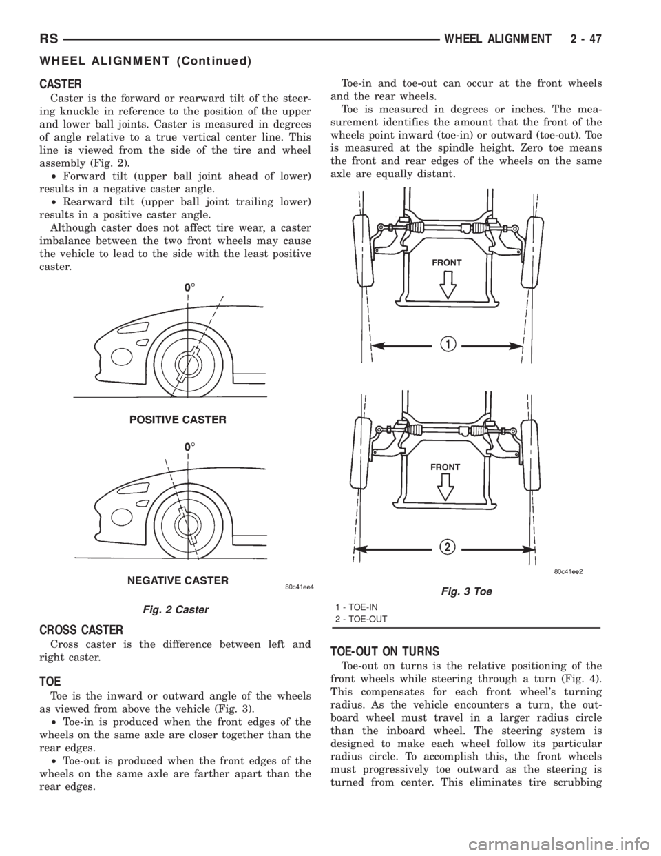
Caster is the forward or rearward tilt of the steer-
ing knuckle in reference to the position of the upper
and lower ball joints. Caster is measured in degrees
of angle relative to a true vertical center line. This
line is viewed from the side of the tire and wheel
assembly (Fig. 2).
²Forward tilt (upper ball joint ahead of lower)
results in a negative caster angle.
²Rearward tilt (upper ball joint trailing lower)
results in a positive caster angle.
Although caster does not affect tire wear, a caster
imbalance between the two front wheels may cause
the vehicle to lead to the side with the least positive
caster.
CROSS CASTER
Cross caster is the difference between left and
right caster.
TOE
Toe is the inward or outward angle of the wheels
as viewed from above the vehicle (Fig. 3).
²Toe-in is produced when the front edges of the
wheels on the same axle are closer together than the
rear edges.
²Toe-out is produced when the front edges of the
wheels on the same axle are farther apart than the
rear edges.Toe-in and toe-out can occur at the front wheels
and the rear wheels.
Toe is measured in degrees or inches. The mea-
surement identifies the amount that the front of the
wheels point inward (toe-in) or outward (toe-out). Toe
is measured at the spindle height. Zero toe means
the front and rear edges of the wheels on the same
axle are equally distant.
TOE-OUT ON TURNS
Toe-out on turns is the relative positioning of the
front wheels while steering through a turn (Fig. 4).
This compensates for each front wheel's turning
radius. As the vehicle encounters a turn, the out-
board wheel must travel in a larger radius circle
than the inboard wheel. The steering system is
designed to make each wheel follow its particular
radius circle. To accomplish this, the front wheels
must progressively toe outward as the steering is
turned from center. This eliminates tire scrubbing
Fig. 2 Caster
Fig. 3 Toe
1 - TOE-IN
2 - TOE-OUT
RSWHEEL ALIGNMENT2-47
WHEEL ALIGNMENT (Continued)
Page 1614 of 4284
lock the front wheels first. Any torque transfer from
the rear axle to the front axle disturbs the ABS/brak-
ing system and causes potential instabilities on a
slippery surface. The BOC de-couples the rear driv-
eline as soon the rear wheels begin to spin faster
than the front wheels (front wheels locked) in order
to provide increased braking stability. Furthermore
the BOC also reduces the likelihood of throttle off
over-steer during cornering. In a throttle off maneu-
ver, the BOC once again de-couples the rear driveline
forcing all the engine brake torque to the front
wheels. This eliminates the chance of lateral slip on
the rear axle and increases it on the front. The vehi-
cle will therefore tend to understeer, a situation
which is considered easier to manage in most circum-
stances. During this maneuver, and during the ABS
braking event, the BOC does not transmit torque
through to the rear wheels. The rear driveline mod-
ule, with the BOC, will perform the same as a front
wheel drive vehicle during these events. The gear
ratio offset between the front and rear differentials
force the BOC into the overrunning mode most of the
time. This allows BOC to significantly reduce the
rolling resistance of the vehicle, which improves fuel
consumption, allows the downsizing of the driveline
components, and prevents the PTU and propshaft
joints from overheating.
OPERATION
In order to achieve all-wheel drive operation in
reverse, the overrunning clutch locking functional
direction must be reversible. The bi-directional over-
running clutch (BOC) changes the operational mode
direction depending on the propeller shaft direction.
The propeller shaft rotates in the clockwise (when
viewed from the front) direction when the vehicle is
moving forward, which indexes the BOC to the for-
ward overrunning position. When the vehicle is in
reverse, the propeller shaft will rotate counter-clock-
wise and index the BOC to the reverse overrunning
position.
The BOC acts as a mechanical stator. It is active
(transmitting torque), or it is not active and in over-
running mode (not transmitting torque). This ªall or
nothingº approach to torque transfer would cause a
sudden application of all available power to the rear
wheels, which is not desirable. Therefore it is run in
series with a viscous coupler to smooth, dampen, and
limit the transmission of torque to the rear axle and
to prevent a step style torque input to the rear axle.
STEADY STATE, LOW TO MODERATE SPEED, NO
FRONT WHEEL SLIP, FORWARD DIRECTION
During normal driving conditions, (no wheel slip),
the inner shaft (front axle) and outer race (viscous
coupler) are running at different speeds due to the
different gear ratios between the front and rear dif-
ferentials. In this condition, the outer race is always
spinning faster (overdriving between 5-32 rpm) than
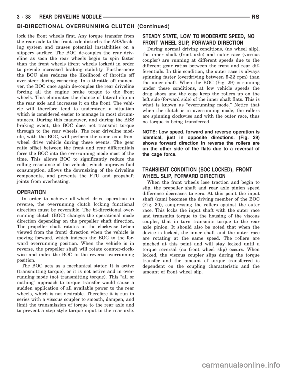
the inner shaft. When the BOC (Fig. 29) is running
under these conditions, at low vehicle speeds the
drag shoes and the cage keep the rollers up on the
left side (forward side) of the inner shaft flats. This is
what is known as ªoverrunning mode.º Notice that
when the clutch is in overrunning mode, the rollers
are spinning clockwise and with the outer race, thus
no torque is being transferred.
NOTE: Low speed, forward and reverse operation is
identical, just in opposite directions. (Fig. 29)
shows forward direction in reverse the rollers are
on the other side of the flats due to a reversal of
the cage force.
TRANSIENT CONDITION (BOC LOCKED), FRONT
WHEEL SLIP, FORWARD DIRECTION
When the front wheels lose traction and begin to
slip, the propeller shaft and rear axle pinion speed
difference decreases to zero. At this point the input
shaft (cam) becomes the driving member of the BOC
(Fig. 30), compressing the rollers against the outer
race. This locks the input shaft with the outer race
and transmits torque to the housing of the viscous
coupler, that in turn transmits torque to the rear
axle pinion. It should also be noted that when the
device is locked, the inner shaft and the outer race
are rotating at the same speed. The rollers are
pinched at this point and will stay locked until a
torque reversal (no front wheel slip) occurs. When
locked, the viscous coupler slips during the torque
transfer and the amount of torque transferred is
dependent on the coupling characteristic and the
amount of front wheel slip.
3 - 38 REAR DRIVELINE MODULERS
BI-DIRECTIONAL OVERRUNNING CLUTCH (Continued)
Page 1616 of 4284
STEADY STATE, HIGH SPEED, NO WHEEL SLIP
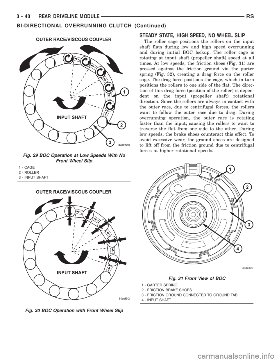
The roller cage positions the rollers on the input
shaft flats during low and high speed overrunning
and during initial BOC lockup. The roller cage is
rotating at input shaft (propeller shaft) speed at all
times. At low speeds, the friction shoes (Fig. 31) are
pressed against the friction ground via the garter
spring (Fig. 32), creating a drag force on the roller
cage. The drag force positions the cage, which in turn
positions the rollers to one side of the flat. The direc-
tion of this drag force (position of the roller) is depen-
dent on the input (propeller shaft) rotational
direction. Since the rollers are always in contact with
the outer race, due to centrifugal forces, the rollers
want to follow the outer race due to drag. During
overrunning operation, the outer race is rotating
faster than the input; causing the rollers to want to
traverse the flat from one side to the other. During
low speeds, the brake shoes counteract this effect. To
avoid excessive wear, the ground shoes are designed
to lift off from the friction ground due to centrifugal
forces at higher rotational speeds.
Fig. 29 BOC Operation at Low Speeds With No
Front Wheel Slip
1 - CAGE
2 - ROLLER
3 - INPUT SHAFT
Fig. 30 BOC Operation with Front Wheel Slip
Fig. 31 Front View of BOC
1 - GARTER SPRING
2 - FRICTION BRAKE SHOES
3 - FRICTION GROUND CONNECTED TO GROUND TAB
4 - INPUT SHAFT
3 - 40 REAR DRIVELINE MODULERS
BI-DIRECTIONAL OVERRUNNING CLUTCH (Continued)
Page 1637 of 4284
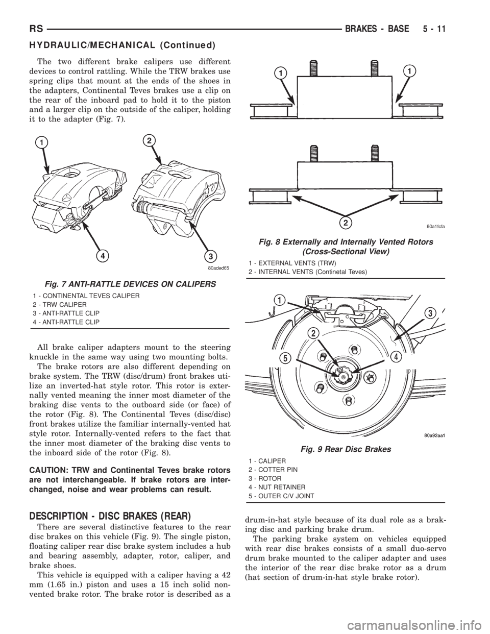
The two different brake calipers use different
devices to control rattling. While the TRW brakes use
spring clips that mount at the ends of the shoes in
the adapters, Continental Teves brakes use a clip on
the rear of the inboard pad to hold it to the piston
and a larger clip on the outside of the caliper, holding
it to the adapter (Fig. 7).
All brake caliper adapters mount to the steering
knuckle in the same way using two mounting bolts.
The brake rotors are also different depending on
brake system. The TRW (disc/drum) front brakes uti-
lize an inverted-hat style rotor. This rotor is exter-
nally vented meaning the inner most diameter of the
braking disc vents to the outboard side (or face) of
the rotor (Fig. 8). The Continental Teves (disc/disc)
front brakes utilize the familiar internally-vented hat
style rotor. Internally-vented refers to the fact that
the inner most diameter of the braking disc vents to
the inboard side of the rotor (Fig. 8).
CAUTION: TRW and Continental Teves brake rotors
are not interchangeable. If brake rotors are inter-
changed, noise and wear problems can result.
DESCRIPTION - DISC BRAKES (REAR)
There are several distinctive features to the rear
disc brakes on this vehicle (Fig. 9). The single piston,
floating caliper rear disc brake system includes a hub
and bearing assembly, adapter, rotor, caliper, and
brake shoes.
This vehicle is equipped with a caliper having a 42
mm (1.65 in.) piston and uses a 15 inch solid non-
vented brake rotor. The brake rotor is described as adrum-in-hat style because of its dual role as a brak-
ing disc and parking brake drum.
The parking brake system on vehicles equipped
with rear disc brakes consists of a small duo-servo
drum brake mounted to the caliper adapter and uses
the interior of the rear disc brake rotor as a drum
(hat section of drum-in-hat style brake rotor).
Fig. 7 ANTI-RATTLE DEVICES ON CALIPERS
1 - CONTINENTAL TEVES CALIPER
2 - TRW CALIPER
3 - ANTI-RATTLE CLIP
4 - ANTI-RATTLE CLIP
Fig. 8 Externally and Internally Vented Rotors
(Cross-Sectional View)
1 - EXTERNAL VENTS (TRW)
2 - INTERNAL VENTS (Continetal Teves)
Fig. 9 Rear Disc Brakes
1 - CALIPER
2 - COTTER PIN
3 - ROTOR
4 - NUT RETAINER
5 - OUTER C/V JOINT
RSBRAKES - BASE5-11
HYDRAULIC/MECHANICAL (Continued)
Page 1660 of 4284

For information on master cylinder application,
bore and type, view the following table:
BRAKE SYSTEMMASTER CYLINDER
BORE/TYPE
Disc/Drum - ABS23.8 mm Conventional
Compensating Port
Disc/Drum - Non-ABS23.8 mm Conventional
Compensating Port
Disc/Disc - ABS25.4 mm (1-1/16 in.)
Conventional
Compensating Port
Disc/Disc ABS With
Traction Control25.4 mm (1-1/16 in.) Dual
Center Port
CAUTION: When replacing a master cylinder, be
sure to use the correct master cylinder for the type
of brake system the vehicle is equipped with.
The body of the master cylinder is an anodized alu-
minum casting. It has a machined bore to accept the
master cylinder pistons and threaded ports with
seats for the hydraulic brake line connections.
The brake fluid reservoir is mounted on the top of
the master cylinder. It is made of a see-through
polypropylene type plastic for easy fluid level view-
ing. A brake fluid level switch is attached to the
brake fluid reservoir.
The master cylinder is not a repairable component
and must be replaced if diagnosed to be functioning
improperly. The brake fluid reservoir and brake fluid
level switch can be replaced separately.
CAUTION: Do not hone the bore of the cylinder as
this will remove the anodized surface from the bore.
OPERATION
When the brake pedal is depressed, the master cyl-
inder primary and secondary pistons apply brake
pressure through the chassis tubes to the brakes at
each tire and wheel assembly.
The master cylinder primary outlet port supplies
hydraulic pressure to the right front and left rear
brakes. The secondary outlet port supplies hydraulic
pressure to the left front and right rear brakes.
STANDARD PROCEDURE - MASTER CYLINDER
BLEEDING
CAUTION: When clamping master cylinder in vise,
only clamp master cylinder by its mounting flange,
do not clamp on primary piston, seal or body of
master cylinder.(1) Clamp the master cylinder in a vise using only
the mounting flange.
NOTE: Two different size bleeding tubes need to be
used depending on which type of master cylinder
the vehicle is equipped with. Vehicles equipped
with traction control have different size brake tubes
and nuts at the master cylinder than the non-trac-
tion control equipped vehicles. Be sure the correct
size bleeding tubes are used when bleeding the
master cylinder.
(2) Thread Bleeding Tubes, Special Tool 8358, for a
non-traction control master cylinder or Special Tool
8129 for a traction control master cylinder into mas-
ter cylinder primary and secondary ports. Position
outlet ends of bleeding tubes in reservoir with the
outlets below surface of brake fluid when reservoir is
filled to its proper level.
(3) Fill brake fluid reservoir with Mopartbrake
fluid or equivalent conforming to DOT 3 (DOT 4 and
DOT 4+ are acceptable) specifications.
(4) Using a wooden dowel, depress push rod slowly,
and then allow pistons to return to released position.
Repeat several times until all air bubbles are
expelled from master cylinder.
(5) Remove bleeding tubes from master cylinder
outlet ports, and then plug outlet ports and install
fill cap on reservoir.
(6) Remove master cylinder from vise.
(7) Install the filler cap on master cylinder fluid
reservoir.
(8) Install master cylinder. (Refer to 5 - BRAKES -
BASE/HYDRAULIC/MECHANICAL/MASTER CYL-
INDER - INSTALLATION)
REMOVAL - MASTER CYLINDER
CAUTION: Vacuum in the power brake booster must
be pumped down (removed) before removing mas-
ter cylinder from power brake booster. This is nec-
essary to prevent the power brake booster from
sucking in any contamination as the master cylin-
der is removed. This can be done simply by pump-
ing the brake pedal, with the vehicle's engine not
running, until a firm feeling brake pedal is achieved.
(1) With engine not running, pump brake pedal
until a firm pedal is achieved (4-5 strokes).
(2) Disconnect negative battery terminal.
(3) Disconnect positive battery terminal.
(4) Remove battery shield.
(5) Remove nut and clamp securing battery to tray,
remove battery.
5 - 34 BRAKES - BASERS
MASTER CYLINDER (Continued)
Page 1817 of 4284
AUDIO
TABLE OF CONTENTS
page page
QUARTER GLASS INTEGRAL ANTENNA
DESCRIPTION............................1
OPERATION.............................1
DIAGNOSIS AND TESTING..................1
QUARTER GLASS INTEGRAL ANTENNA......1
ANTENNA MODULE
DESCRIPTION............................2OPERATION.............................2
DIAGNOSIS AND TESTING..................2
ANTENNA MODULE......................2
REMOVAL...............................2
INSTALLATION............................2
QUARTER GLASS INTEGRAL
ANTENNA
DESCRIPTION
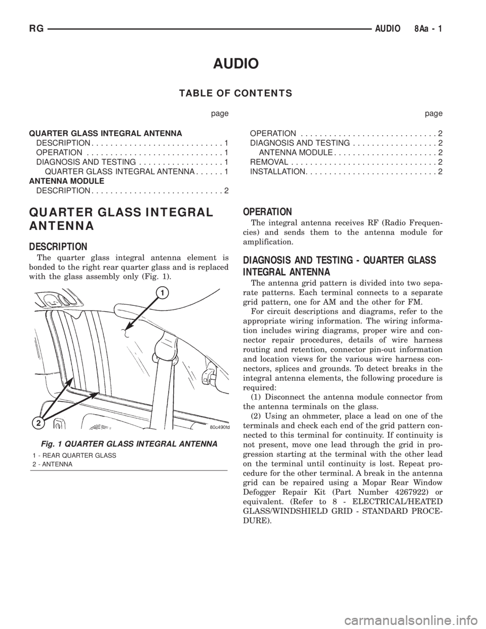
The quarter glass integral antenna element is
bonded to the right rear quarter glass and is replaced
with the glass assembly only (Fig. 1).
OPERATION
The integral antenna receives RF (Radio Frequen-
cies) and sends them to the antenna module for
amplification.
DIAGNOSIS AND TESTING - QUARTER GLASS
INTEGRAL ANTENNA
The antenna grid pattern is divided into two sepa-
rate patterns. Each terminal connects to a separate
grid pattern, one for AM and the other for FM.
For circuit descriptions and diagrams, refer to the
appropriate wiring information. The wiring informa-
tion includes wiring diagrams, proper wire and con-
nector repair procedures, details of wire harness
routing and retention, connector pin-out information
and location views for the various wire harness con-
nectors, splices and grounds. To detect breaks in the
integral antenna elements, the following procedure is
required:
(1) Disconnect the antenna module connector from
the antenna terminals on the glass.
(2) Using an ohmmeter, place a lead on one of the
terminals and check each end of the grid pattern con-
nected to this terminal for continuity. If continuity is
not present, move one lead through the grid in pro-
gression starting at the terminal with the other lead
on the terminal until continuity is lost. Repeat pro-
cedure for the other terminal. A break in the antenna
grid can be repaired using a Mopar Rear Window
Defogger Repair Kit (Part Number 4267922) or
equivalent. (Refer to 8 - ELECTRICAL/HEATED
GLASS/WINDSHIELD GRID - STANDARD PROCE-
DURE).
Fig. 1 QUARTER GLASS INTEGRAL ANTENNA
1 - REAR QUARTER GLASS
2 - ANTENNA
RGAUDIO8Aa-1
Page 1897 of 4284
HEATED SYSTEMS
TABLE OF CONTENTS
page page
HEATED GLASS........................... 1
HEATED MIRRORS......................... 5HEATED SEAT SYSTEM..................... 7
HEATED GLASS
TABLE OF CONTENTS
page page
HEATED GLASS
DESCRIPTION............................1
OPERATION.............................2
DEFOGGER RELAY
DESCRIPTION............................2
REAR WINDOW DEFOGGER GRID
STANDARD PROCEDURE...................2
GRID LINE REPAIR-REAR.................2REAR WINDOW DEFOGGER SWITCH
DESCRIPTION............................2
OPERATION.............................2
WINDSHIELD GRID
DIAGNOSIS AND TESTING..................3
SYSTEM TEST..........................3
STANDARD PROCEDURE...................3
GRID LINE AND TERMINAL REPAIR.........3
HEATED GLASS
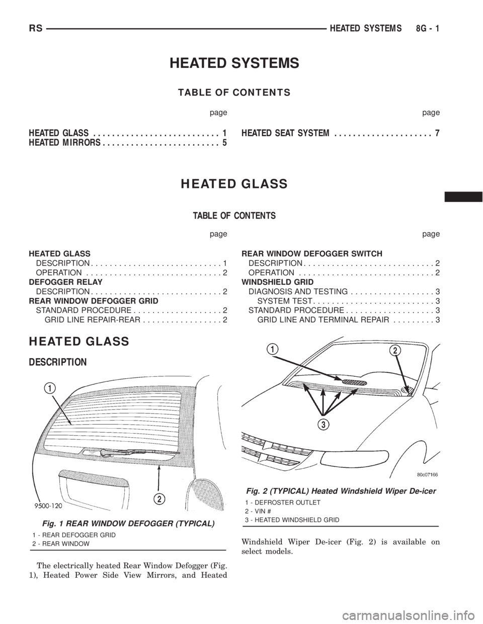
DESCRIPTION
The electrically heated Rear Window Defogger (Fig.
1), Heated Power Side View Mirrors, and HeatedWindshield Wiper De-icer (Fig. 2) is available on
select models.
Fig. 1 REAR WINDOW DEFOGGER (TYPICAL)
1 - REAR DEFOGGER GRID
2 - REAR WINDOW
Fig. 2 (TYPICAL) Heated Windshield Wiper De-icer
1 - DEFROSTER OUTLET
2 - VIN #
3 - HEATED WINDSHIELD GRID
RSHEATED SYSTEMS8G-1
Page 1898 of 4284
OPERATION
The Rear Window Defogger (Fig. 1) system consists
of two vertical bus bars linked by a series of grid
lines on the inside surface of the rear window. The
electrical circuit consists of the rear defogger switch
in the HVAC control assembly and a relay with timer
switch to turn OFF the system after ten minutes.
The main feed circuit is protected by fuse 13 (40
amp) in the Power Distribution Center (PDC) which
is integrated as a unit call Integrated Power Module
(IPM). The rear defogger switch and relay also acti-
vates the heated power side view mirrors and heated
windshield wiper de-icer. The heated windshield
wiper de-icer is powered by the RUN/ACC relay in
the IPM and feed thru fuse #11 (20 amp) in the PDC.
The heated mirror circuit is protected by a non-servi-
cable Positive Temperature Coefficient (PTC) located
inside the PDC. The heated windshield wiper de-icer
circuit is protected by fuse 11 (20 amp) in the PDC.
The Heated Windshield Wiper Deicer is also acti-
vated when the DEFROST mode is selected on the
HVAC. In the DEFROST mode the rear defogger
relay/timer is bypassed, the heated windshield wiper
de-icer will stay ON until the another mode is
selected. For circuit information and component loca-
tion refer to appropriate section for Wiring Diagrams.
CAUTION:
Since grid lines can be damaged or scraped off
with sharp instruments, care should be taken in
cleaning the glass or removing foreign materials,
decals or stickers. Normal glass cleaning solvents
or hot water used with rags or toweling is recom-
mended.
DEFOGGER RELAY
DESCRIPTION
There is no heated glass relay it is integrated into
the (E.B.L) relay that is located in the IPM in the
engine compartment.
REAR WINDOW DEFOGGER
GRID
STANDARD PROCEDURE - GRID LINE
REPAIR-REAR
For Grid repair procedure for the rear window
defogger (Refer to 8 - ELECTRICAL/HEATED
GLASS/WINDSHIELD GRID - STANDARD PROCE-
DURE).
REAR WINDOW DEFOGGER
SWITCH
DESCRIPTION
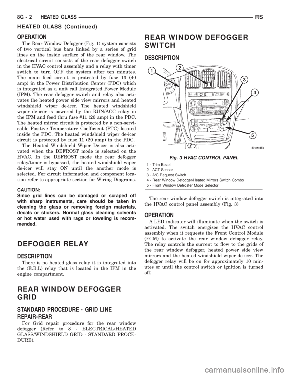
The rear window defogger switch is integrated into
the HVAC control panel assembly (Fig. 3)
OPERATION
A LED indicator will illuminate when the switch is
activated. The switch energizes the HVAC control
assembly when it requests the Front Control Module
(FCM) to activate the rear window defogger relay.
The relay controls the current to flow to the grids of
the rear window defogger, heated power side view
mirrors and the heated windshield wiper de-icer. The
defogger relay will be on for approximately 10 min-
utes or until the control switch or ignition is turned
off.
Fig. 3 HVAC CONTROL PANEL
1 - Trim Bezel
2 - ACT Sensor
3 - A/C Request Switch
4 - Rear Window Defogger/Heated Mirrors Switch Combo
5 - Front Window Defroster Mode Selector
8G - 2 HEATED GLASSRS
HEATED GLASS (Continued)
Page 1901 of 4284
HEATED MIRRORS
TABLE OF CONTENTS
page page
HEATED MIRRORS
DESCRIPTION............................5
OPERATION.............................5
DIAGNOSIS AND TESTING..................5
HEATED MIRROR TEST...................5
MIRROR SWITCH
DESCRIPTION............................5OPERATION.............................5
HEATED MIRROR GRID
STANDARD PROCEDURE...................6
HEATED MIRROR.......................6
RELAY
DESCRIPTION............................6
HEATED MIRRORS
DESCRIPTION
Heated mirrors are available on models with
Power Mirrors and Rear Window Defogger only.
OPERATION
The heated mirror is controlled by the rear window
defogger switch. The heated mirror is ON when the
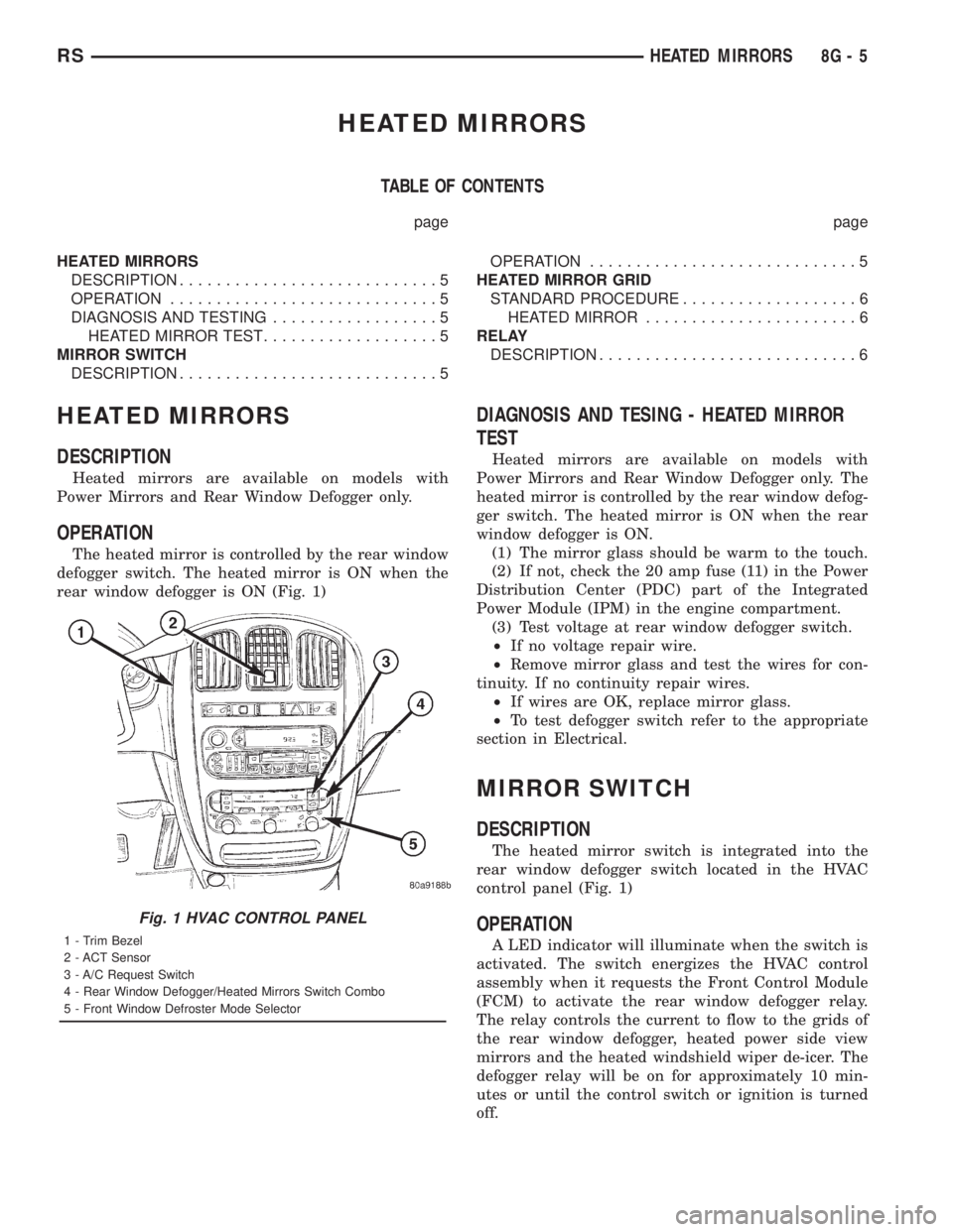
rear window defogger is ON (Fig. 1)
DIAGNOSIS AND TESING - HEATED MIRROR
TEST
Heated mirrors are available on models with
Power Mirrors and Rear Window Defogger only. The
heated mirror is controlled by the rear window defog-
ger switch. The heated mirror is ON when the rear
window defogger is ON.
(1) The mirror glass should be warm to the touch.
(2) If not, check the 20 amp fuse (11) in the Power
Distribution Center (PDC) part of the Integrated
Power Module (IPM) in the engine compartment.
(3) Test voltage at rear window defogger switch.
²If no voltage repair wire.
²Remove mirror glass and test the wires for con-
tinuity. If no continuity repair wires.
²If wires are OK, replace mirror glass.
²To test defogger switch refer to the appropriate
section in Electrical.
MIRROR SWITCH
DESCRIPTION
The heated mirror switch is integrated into the
rear window defogger switch located in the HVAC
control panel (Fig. 1)
OPERATION
A LED indicator will illuminate when the switch is
activated. The switch energizes the HVAC control
assembly when it requests the Front Control Module
(FCM) to activate the rear window defogger relay.
The relay controls the current to flow to the grids of
the rear window defogger, heated power side view
mirrors and the heated windshield wiper de-icer. The
defogger relay will be on for approximately 10 min-
utes or until the control switch or ignition is turned
off.
Fig. 1 HVAC CONTROL PANEL
1 - Trim Bezel
2 - ACT Sensor
3 - A/C Request Switch
4 - Rear Window Defogger/Heated Mirrors Switch Combo
5 - Front Window Defroster Mode Selector
RSHEATED MIRRORS8G-5