rear view CHRYSLER VOYAGER 2001 User Guide
[x] Cancel search | Manufacturer: CHRYSLER, Model Year: 2001, Model line: VOYAGER, Model: CHRYSLER VOYAGER 2001Pages: 4284, PDF Size: 83.53 MB
Page 308 of 4284
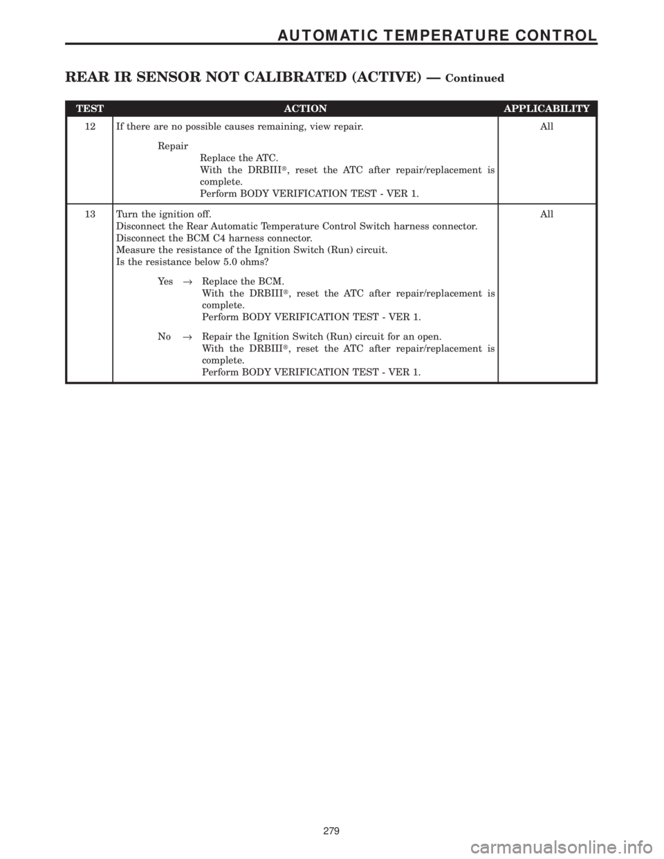
TEST ACTION APPLICABILITY
12 If there are no possible causes remaining, view repair. All
Repair
Replace the ATC.
With the DRBIIIt, reset the ATC after repair/replacement is
complete.
Perform BODY VERIFICATION TEST - VER 1.
13 Turn the ignition off.
Disconnect the Rear Automatic Temperature Control Switch harness connector.
Disconnect the BCM C4 harness connector.
Measure the resistance of the Ignition Switch (Run) circuit.
Is the resistance below 5.0 ohms?All
Ye s®Replace the BCM.
With the DRBIIIt, reset the ATC after repair/replacement is
complete.
Perform BODY VERIFICATION TEST - VER 1.
No®Repair the Ignition Switch (Run) circuit for an open.
With the DRBIIIt, reset the ATC after repair/replacement is
complete.
Perform BODY VERIFICATION TEST - VER 1.
279
AUTOMATIC TEMPERATURE CONTROL
REAR IR SENSOR NOT CALIBRATED (ACTIVE) ÐContinued
Page 310 of 4284

TEST ACTION APPLICABILITY
4 Turn the ignition off.
Disconnect the Rear Automatic Temperature Control Switch harness connector.
Disconnect the ATC C2 harness connector.
Turn the ignition on.
Measure the voltage of the KDB Data circuit.
Is the voltage above 1.0 volt?All
Ye s®Repair the KDB Data circuit for a short to voltage.
With the DRBIIIt, reset the ATC after repair/replacement is
complete.
Perform BODY VERIFICATION TEST - VER 1.
No®Go To 5
5 Turn the ignition off.
Disconnect the Rear Automatic Temperature Control Switch harness connector.
Use Scope input cable CH7058, Cable to Probe adapter CH7062, and the red and
black test probes.
Connect the scope input cable to the channel one connector on the DRB. Attach the
red and black leads and the cable to probe adapter to the scope input cable.
Select Lab Scope.
Select Live.
Select 12 volt square wave.
Press F2 for Scope.
Press F2 and use the arrows to set the voltage range to 20 volts, the Offset to 4.0, and
the Probe to x10. Press F2 again and set the divisions to 40ms/Div, then press F2
again when complete.
Connect the Black lead to the chassis ground. Connect the Red lead to the KDB Clock
circuit in the Rear Automatic Temperature Control Switch harness connector.
Turn the ignition on.
Observe the voltage display on the DRB Lab Scope.
NOTE: The lab scope pattern should look similar to the example given in the
support material and cycle from approximately 0 volts to 8.0 volts.
Did the lab scope pattern and voltage react as noted above?All
Ye s®Go To 6
No®Go To 7
6 If there are no possible causes remaining, view repair. All
Repair
Replace the Rear Automatic Temperature Control Switch.
With the DRBIIIt, reset the ATC after repair/replacement is
complete.
Perform BODY VERIFICATION TEST - VER 1.
7 Turn the ignition off.
Disconnect the Rear Automatic Temperature Control Switch harness connector.
Disconnect the ATC C2 harness connector.
Turn the ignition on.
Measure the voltage of the KDB Clock circuit.
Is the voltage above 1.0 volt?All
Ye s®Repair the KDB Clock circuit for a short to voltage.
With the DRBIIIt, reset the ATC after repair/replacement is
complete.
Perform BODY VERIFICATION TEST - VER 1.
No®Go To 8
281
AUTOMATIC TEMPERATURE CONTROL
REAR KEYBOARD FAULT (ACTIVE) ÐContinued
Page 311 of 4284
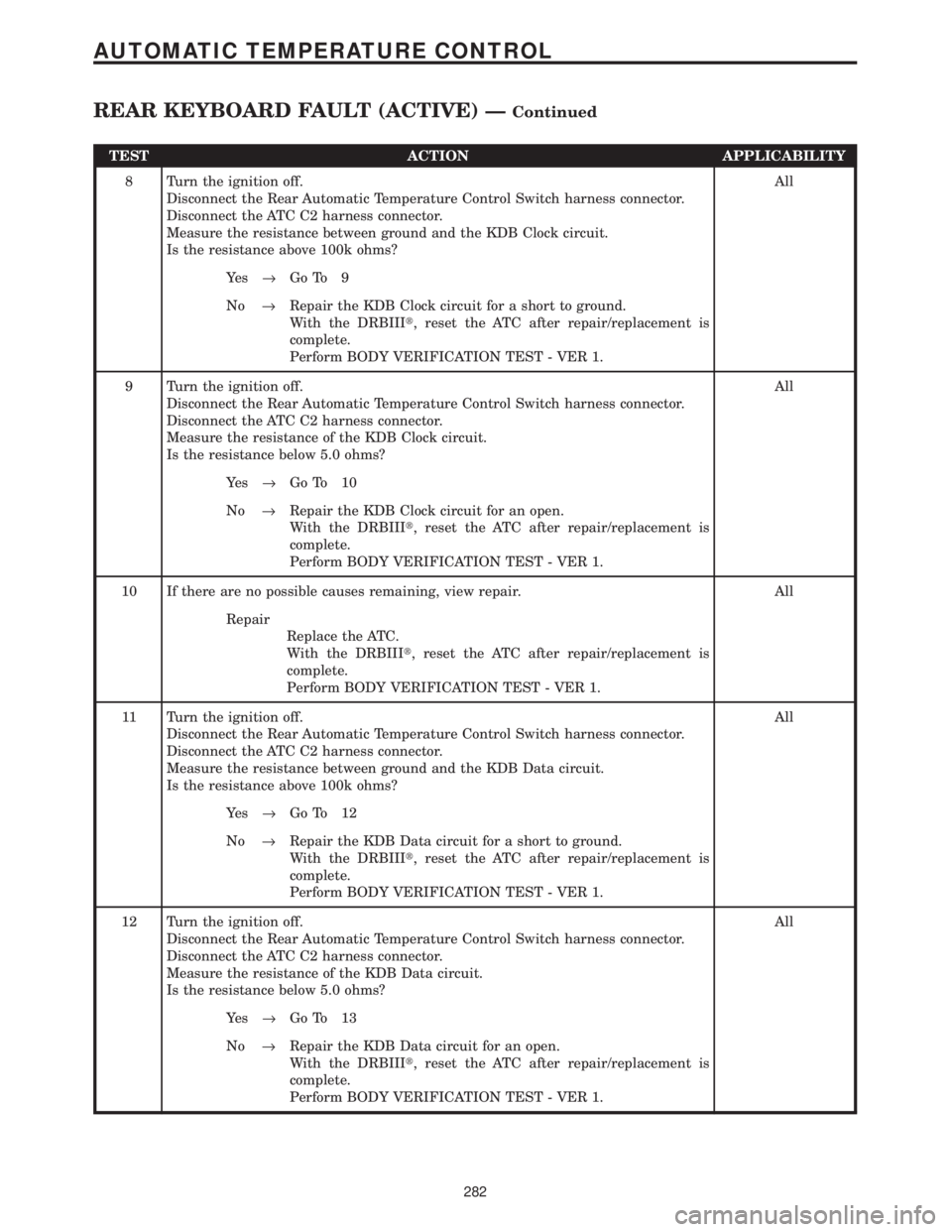
TEST ACTION APPLICABILITY
8 Turn the ignition off.
Disconnect the Rear Automatic Temperature Control Switch harness connector.
Disconnect the ATC C2 harness connector.
Measure the resistance between ground and the KDB Clock circuit.
Is the resistance above 100k ohms?All
Ye s®Go To 9
No®Repair the KDB Clock circuit for a short to ground.
With the DRBIIIt, reset the ATC after repair/replacement is
complete.
Perform BODY VERIFICATION TEST - VER 1.
9 Turn the ignition off.
Disconnect the Rear Automatic Temperature Control Switch harness connector.
Disconnect the ATC C2 harness connector.
Measure the resistance of the KDB Clock circuit.
Is the resistance below 5.0 ohms?All
Ye s®Go To 10
No®Repair the KDB Clock circuit for an open.
With the DRBIIIt, reset the ATC after repair/replacement is
complete.
Perform BODY VERIFICATION TEST - VER 1.
10 If there are no possible causes remaining, view repair. All
Repair
Replace the ATC.
With the DRBIIIt, reset the ATC after repair/replacement is
complete.
Perform BODY VERIFICATION TEST - VER 1.
11 Turn the ignition off.
Disconnect the Rear Automatic Temperature Control Switch harness connector.
Disconnect the ATC C2 harness connector.
Measure the resistance between ground and the KDB Data circuit.
Is the resistance above 100k ohms?All
Ye s®Go To 12
No®Repair the KDB Data circuit for a short to ground.
With the DRBIIIt, reset the ATC after repair/replacement is
complete.
Perform BODY VERIFICATION TEST - VER 1.
12 Turn the ignition off.
Disconnect the Rear Automatic Temperature Control Switch harness connector.
Disconnect the ATC C2 harness connector.
Measure the resistance of the KDB Data circuit.
Is the resistance below 5.0 ohms?All
Ye s®Go To 13
No®Repair the KDB Data circuit for an open.
With the DRBIIIt, reset the ATC after repair/replacement is
complete.
Perform BODY VERIFICATION TEST - VER 1.
282
AUTOMATIC TEMPERATURE CONTROL
REAR KEYBOARD FAULT (ACTIVE) ÐContinued
Page 312 of 4284
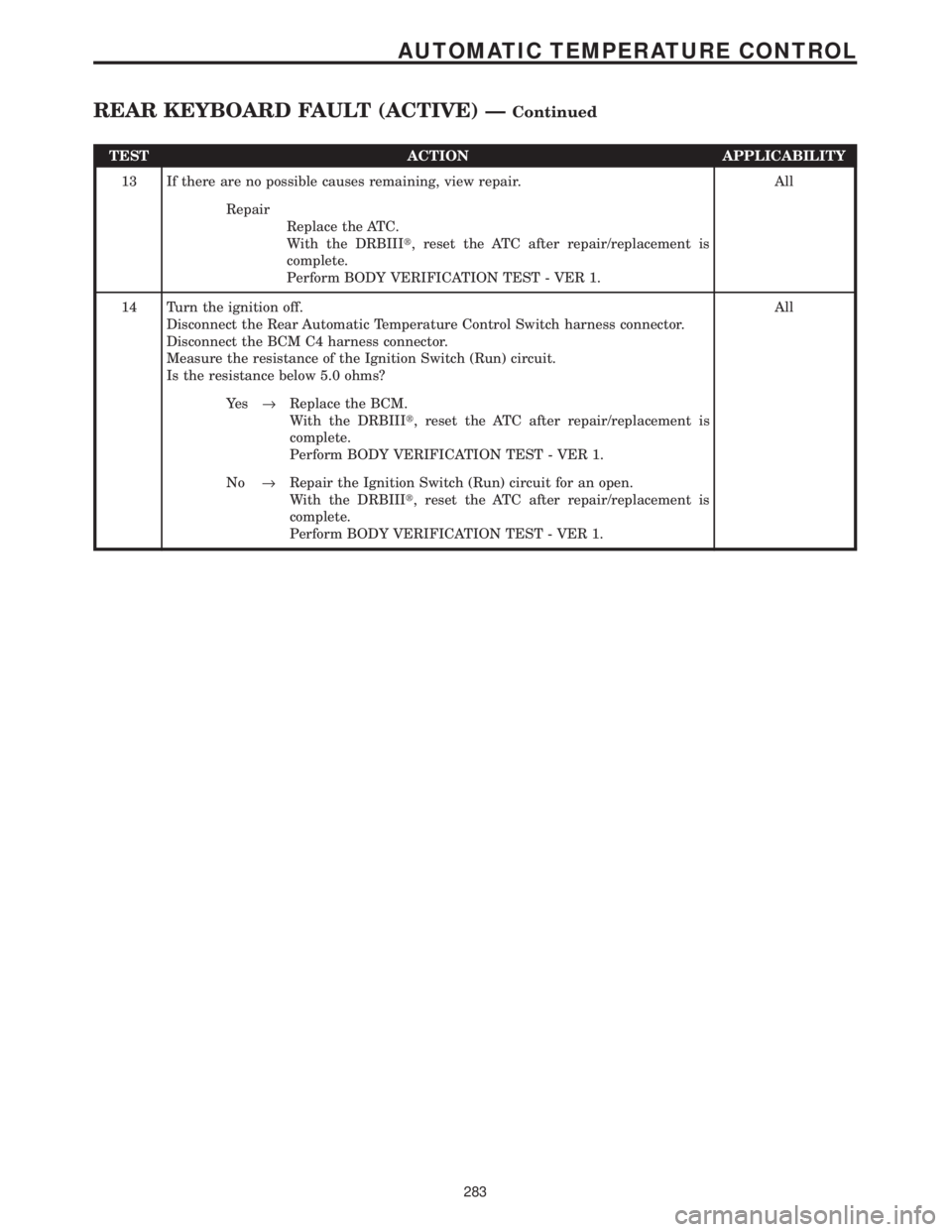
TEST ACTION APPLICABILITY
13 If there are no possible causes remaining, view repair. All
Repair
Replace the ATC.
With the DRBIIIt, reset the ATC after repair/replacement is
complete.
Perform BODY VERIFICATION TEST - VER 1.
14 Turn the ignition off.
Disconnect the Rear Automatic Temperature Control Switch harness connector.
Disconnect the BCM C4 harness connector.
Measure the resistance of the Ignition Switch (Run) circuit.
Is the resistance below 5.0 ohms?All
Ye s®Replace the BCM.
With the DRBIIIt, reset the ATC after repair/replacement is
complete.
Perform BODY VERIFICATION TEST - VER 1.
No®Repair the Ignition Switch (Run) circuit for an open.
With the DRBIIIt, reset the ATC after repair/replacement is
complete.
Perform BODY VERIFICATION TEST - VER 1.
283
AUTOMATIC TEMPERATURE CONTROL
REAR KEYBOARD FAULT (ACTIVE) ÐContinued
Page 314 of 4284
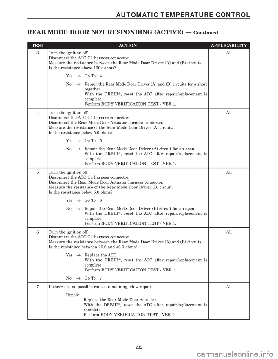
TEST ACTION APPLICABILITY
3 Turn the ignition off.
Disconnect the ATC C1 harness connector.
Measure the resistance between the Rear Mode Door Driver (A) and (B) circuits.
Is the resistance above 100k ohms?All
Ye s®Go To 4
No®Repair the Rear Mode Door Driver (A) and (B) circuits for a short
together.
With the DRBIIIt, reset the ATC after repair/replacement is
complete.
Perform BODY VERIFICATION TEST - VER 1.
4 Turn the ignition off.
Disconnect the ATC C1 harness connector.
Disconnect the Rear Mode Door Actuator harness connector.
Measure the resistance of the Rear Mode Door Driver (A) circuit.
Is the resistance below 5.0 ohms?All
Ye s®Go To 5
No®Repair the Rear Mode Door Driver (A) circuit for an open.
With the DRBIIIt, reset the ATC after repair/replacement is
complete.
Perform BODY VERIFICATION TEST - VER 1.
5 Turn the ignition off.
Disconnect the ATC C1 harness connector.
Disconnect the Rear Mode Door Actuator harness connector.
Measure the resistance of the Rear Mode Door Driver (B) circuit.
Is the resistance below 5.0 ohms?All
Ye s®Go To 6
No®Repair the Rear Mode Door Driver (B) circuit for an open.
With the DRBIIIt, reset the ATC after repair/replacement is
complete.
Perform BODY VERIFICATION TEST - VER 1.
6 Turn the ignition off.
Disconnect the ATC C1 harness connector.
Measure the resistance between the Rear Mode Door Driver (A) and (B) circuits.
Is the resistance between 26.0 and 46.0 ohms?All
Ye s®Replace the ATC.
With the DRBIIIt, reset the ATC after repair/replacement is
complete.
Perform BODY VERIFICATION TEST - VER 1.
No®Go To 7
7 If there are no possible causes remaining, view repair. All
Repair
Replace the Rear Mode Door Actuator.
With the DRBIIIt, reset the ATC after repair/replacement is
complete.
Perform BODY VERIFICATION TEST - VER 1.
285
AUTOMATIC TEMPERATURE CONTROL
REAR MODE DOOR NOT RESPONDING (ACTIVE) ÐContinued
Page 583 of 4284
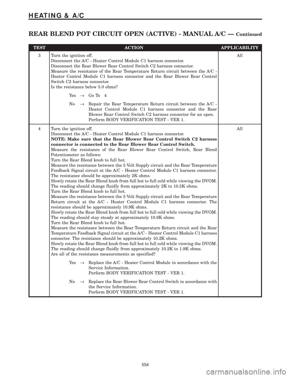
TEST ACTION APPLICABILITY
3 Turn the ignition off.
Disconnect the A/C - Heater Control Module C1 harness connector.
Disconnect the Rear Blower Rear Control Switch C2 harness connector.
Measure the resistance of the Rear Temperature Return circuit between the A/C -
Heater Control Module C1 harness connector and the Rear Blower Rear Control
Switch C2 harness connector.
Is the resistance below 5.0 ohms?All
Ye s®Go To 4
No®Repair the Rear Temperature Return circuit between the A/C -
Heater Control Module C1 harness connector and the Rear
Blower Rear Control Switch C2 harness connector for an open.
Perform BODY VERIFICATION TEST - VER 1.
4 Turn the ignition off.
Disconnect the A/C - Heater Control Module C1 harness connector.
NOTE: Make sure that the Rear Blower Rear Control Switch C2 harness
connector is connected to the Rear Blower Rear Control Switch.
Measure the resistance of the Rear Blower Rear Control Switch, Rear Blend
Potentiometer as follows:
Turn the Rear Blend knob to full hot.
Measure the resistance between the 5 Volt Supply circuit and the Rear Temperature
Feedback Signal circuit at the A/C - Heater Control Module C1 harness connector.
The resistance should be approximately 2K ohms.
Slowly rotate the Rear Blend knob from full hot to full cold while viewing the DVOM.
The reading should change fluidly from approximately 2K to 10.5K ohms.
Turn the Rear Blend knob to full hot.
Measure the resistance between the 5 Volt Supply circuit and the Rear Temperature
Return circuit at the A/C - Heater Control Module C1 harness connector. The
resistance should be approximately 10.9K ohms.
Slowly rotate the Rear Blend knob from full hot to full cold while viewing the DVOM.
The reading should stay steady at approximately 10.9K ohms.
Turn the Rear Blend knob to full hot.
Measure the resistance between the Rear Temperature Return circuit and the Rear
Temperature Feedback Signal circuit at the A/C - Heater Control Module C1 harness
connector. The resistance should be approximately 10.2K ohms.
Slowly rotate the Rear Blend knob from full hot to full cold while viewing the DVOM.
The reading should change fluidly from approximately 10.2K to 1.9K ohms.
Are all of the resistance measurements as specified?All
Ye s®Replace the A/C - Heater Control Module in accordance with the
Service Information.
Perform BODY VERIFICATION TEST - VER 1.
No®Replace the Rear Blower Rear Control Switch in accordance with
the Service Information.
Perform BODY VERIFICATION TEST - VER 1.
554
HEATING & A/C
REAR BLEND POT CIRCUIT OPEN (ACTIVE) - MANUAL A/C ÐContinued
Page 598 of 4284

Symptom:
FRONT FOG LAMP INDICATOR SHORT TO GROUND
POSSIBLE CAUSES
INTERMITTENT WIRING AND CONNECTORS
FRONT FOG LAMP INDICATOR CIRCUIT SHORT TO GROUND
HEADLAMP SWITCH
BODY CONTROL MODULE
TEST ACTION APPLICABILITY
1 Turn the ignition on.
With the DRBIIIt, record and erase Body Control Module DTC's.
Turn the ignition off, wait 15 seconds, then turn the ignition on.
With the DRBIIIt, read DTCs.
Does the DRBIIItdisplay FRONT FOG LAMP INDICATOR SHORT TO GROUND?All
Ye s®Go To 2
No®Go To 6
2 Turn the ignition off to the lock position.
Note: Check connectors - Clean/repair as necessary.
Ignition on, engine not running.
Turn ON the Front Fog Lamps.
Using a 12-volt test light connected to ground, back probe the Rear Fog Lamp
Indicator circuit in the Headlamp Switch harness connector.
NOTE: The test light must illuminate brightly. Compare the brightness to
that of a direct connection to the battery.
Does the test light illuminate brightly?All
Ye s®Go To 3
No®Go To 4
3 If there are no possible causes remaining, view repair. All
Repair
Replace the Headlamp Switch.
Perform BODY VERIFICATION TEST - VER 1.
4 Turn the ignition off to the lock position.
Disconnect the Body Control Module harness connector.
Disconnect the Headlamp Switch harness connector.
Note: Check connectors - Clean/repair as necessary.
Measure the resistance between ground and the Front Fog Lamp Indicator circuit.
Is the resistance below 5.0 ohms?All
Ye s®Repair the Front Fog Lamp Indicator circuit for a short to ground.
Perform BODY VERIFICATION TEST - VER 1.
No®Go To 5
5 If there are no possible causes remaining, view repair. All
Repair
Replace the Body Control Module.
Perform BODY VERIFICATION TEST - VER 1.
569
INSTRUMENT CLUSTER
Page 630 of 4284

TEST ACTION APPLICABILITY
4 Turn the ignition off to the lock position.
Disconnect the Body Control Module harness connector.
Disconnect the Headlamp Switch harness connector.
Note: Check connectors - Clean/repair as necessary.
Ignition on, engine not running.
Measure the voltage of the Rear Fog Lamp Indicator circuit in the Headlamp Switch
harness connector.
Is the voltage above 0.5 volt?All
Ye s®Repair the Rear Fog Lamp Indicator circuit for a short to voltage.
Perform BODY VERIFICATION TEST - VER 1.
No®Go To 5
5 If there are no possible causes remaining, view repair. All
Repair
Replace the Headlamp Switch.
Perform BODY VERIFICATION TEST - VER 1.
6 Turn the ignition off to the lock position.
Disconnect the Body Control Module harness connector.
Disconnect the Headlamp Switch harness connector.
Note: Check connectors - Clean/repair as necessary.
Measure the resistance of the Rear Fog Lamp Indicator circuit from the Body Control
Module harness connector to the Headlamp Switch harness connector.
Is the resistance above 5.0 ohms?All
Ye s®Repair the Rear Fog Lamp Indicator circuit for an open.
Perform BODY VERIFICATION TEST - VER 1.
No®Go To 7
7 If there are no possible causes remaining, view repair. All
Repair
Replace the Body Control Module.
Perform BODY VERIFICATION TEST - VER 1.
8 The conditions necessary to set this DTC are not present at this time.
Using the schematics as a guide, inspect the wiring and connectors specific to this
circuit.
Wiggle the wiring while checking for shorts and open circuits.
Were there any problems found?All
Ye s®Repair as necessary.
Perform BODY VERIFICATION TEST - VER 1.
No®Test Complete.
601
INSTRUMENT CLUSTER
REAR FOG INDICATOR OUTPUT OPEN ÐContinued
Page 631 of 4284

Symptom:
REAR FOG INDICATOR OUTPUT SHORT
POSSIBLE CAUSES
INTERMITTENT WIRING AND CONNECTORS
REAR FOG LAMP INDICATOR CIRCUIT SHORT TO GROUND
HEADLAMP SWITCH
BODY CONTROL MODULE
TEST ACTION APPLICABILITY
1 Turn the ignition on.
With the DRBIIIt, record and erase Body Control Module DTC's.
Turn the ignition off, wait 15 seconds, then turn the ignition on.
With the DRBIIIt, read DTCs.
Does the DRBIIItdisplay REAR FOG LAMP INDICATOR SHORT TO GROUND?All
Ye s®Go To 2
No®Go To 6
2 Turn the ignition off to the lock position.
Note: Check connectors - Clean/repair as necessary.
Ignition on, engine not running.
Turn ON the Rear Fog Lamps.
Using a 12-volt test light connected to ground, back probe the Rear Fog Lamp
Indicator circuit in the Headlamp Switch harness connector.
NOTE: The test light must illuminate brightly. Compare the brightness to
that of a direct connection to the battery.
Does the test light illuminate brightly?All
Ye s®Go To 3
No®Go To 4
3 If there are no possible causes remaining, view repair. All
Repair
Replace the Headlamp Switch.
Perform BODY VERIFICATION TEST - VER 1.
4 Turn the ignition off to the lock position.
Disconnect the Body Control Module harness connector.
Disconnect the Headlamp Switch harness connector.
Note: Check connectors - Clean/repair as necessary.
Measure the resistance between ground and the Rear Fog Lamp Indicator circuit.
Is the resistance below 5.0 ohms?All
Ye s®Repair the Rear Fog Lamp Indicator circuit for a short to ground.
Perform BODY VERIFICATION TEST - VER 1.
No®Go To 5
5 If there are no possible causes remaining, view repair. All
Repair
Replace the Body Control Module.
Perform BODY VERIFICATION TEST - VER 1.
602
INSTRUMENT CLUSTER
Page 688 of 4284
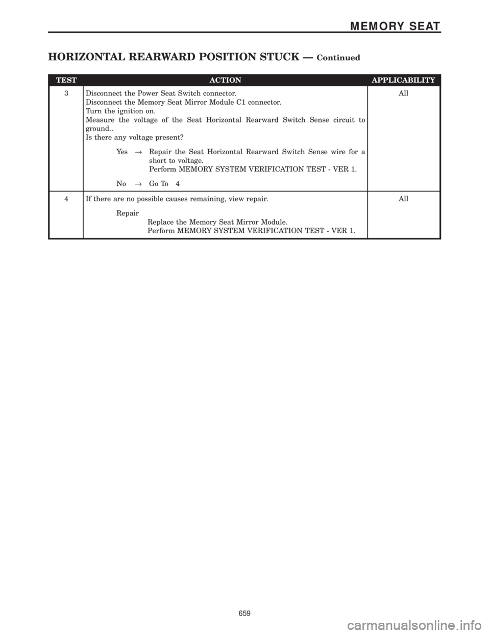
TEST ACTION APPLICABILITY
3 Disconnect the Power Seat Switch connector.
Disconnect the Memory Seat Mirror Module C1 connector.
Turn the ignition on.
Measure the voltage of the Seat Horizontal Rearward Switch Sense circuit to
ground..
Is there any voltage present?All
Ye s®Repair the Seat Horizontal Rearward Switch Sense wire for a
short to voltage.
Perform MEMORY SYSTEM VERIFICATION TEST - VER 1.
No®Go To 4
4 If there are no possible causes remaining, view repair. All
Repair
Replace the Memory Seat Mirror Module.
Perform MEMORY SYSTEM VERIFICATION TEST - VER 1.
659
MEMORY SEAT
HORIZONTAL REARWARD POSITION STUCK ÐContinued