rear view CHRYSLER VOYAGER 2001 Workshop Manual
[x] Cancel search | Manufacturer: CHRYSLER, Model Year: 2001, Model line: VOYAGER, Model: CHRYSLER VOYAGER 2001Pages: 4284, PDF Size: 83.53 MB
Page 1942 of 4284
LAMPS/LIGHTING - EXTERIOR
DESCRIPTION
LAMP SYSTEMS
RS vehicles use lighting on the interior and exte-
rior of the vehicle for illuminating and indicating
purposes. Lighting circuits are protected by fuses.
Lighting circuits require an overload protected power
source, on/off device, lamps and body ground to oper-
ate properly. Plastic lamps require a wire in the har-
ness to supply body ground to the lamp socket.
Replace sockets and bulbs that are corroded.
Some of the interior and exterior lighting functions
are governed by the Body Control Module. The head-
lamp, dome, and the door ajar switches provide sig-
nals to the Body Control Module. The Body Control
Module in turn sends a J1850 message to the Front
Control Module (FCM) to enable the necessary driv-
ers to set the required illumination configuration.
Wire connectors can make intermittent contact or
become corroded. Before coupling wire connectors,
inspect the terminals inside the connector. Male termi-
nals should not be bent or disengaged from the insu-
lator. Female terminals should not be sprung open or
disengaged from the insulator. Bent and sprung termi-
nals can be repaired using needle nose pliers and pick
tool. Corroded terminals appear chalky or green. Cor-
roded terminals should be replaced to avoid recur-
rence of the problem symptoms.
Begin electrical system failure diagnosis by testing
related fuses in the fuse block and intelligent power
module. Verify that bulbs are in good condition and
test continuity of the circuit ground. Refer to the
appropriate wiring information. The wiring informa-
tion includes wiring diagrams, proper wire and con-
nector repair procedures, details of wire harness
routing and retention, connector pin-out information
and location views for the various wire harness con-
nectors, splices and grounds.
AUTOMATIC HEADLAMP SYSTEM
The Automatic Headlamp system turns the instru-
mentation and exterior illumination lamps ON when
the ambient light levels are Night and OFF when
light levels are Day.
DAYTIME RUNNING LAMPS
Operating the high-beam headlamps at reduced
power provides daytime running lamps, which are
required on all new Canadian vehicles.
HEADLAMPS ON WITH WINDSHIELD WIPERS
For vehicles equipped with the Automatic Head-
lamp System, the instrumentation and exterior illu-
mination lamps will be turned ON when theheadlamp switch is in the AUTO position, RPM >
450 and the windshield wipers have been in the
intermittent, low or high mode of operation for more
than ten seconds. When the windshield wipers are
turned OFF the Body Control Module will determine
if the instrumentation and exterior illumination
lamps should remain ON base upon the current
ambient light level.
HEADLAMP SYSTEM
The configuration of the headlamp system of head-
lamps, park lamps and fog lamps is determined by
the BCM. The BCM determines the lighting configu-
ration as a result of the inputs from the ignition
switch, headlamp switch and multifunction switch. A
J1850 is transmitted from the BCM to the FCM to
enable the necessary drivers to set the illumination
configuration. Four wires are connected between the
headlamp switch and the BCM. The first wire con-
tains information regarding the position of the head-
lamp switch (Off, Automatic Headlamps, Automatic
Headlamp switch fog, Park with Fog, Head, or Head
with Fog Lamps). The second wire contains informa-
tion regarding the position of the dimmer switch
(Dome Lamp, Daytime Brightness, Dimming Level or
Off). The third wire is a dedicated signal return
(ground) wire. The fourth wire provides power to the
front fog lamp indicator.
HEADLAMP TIME DELAY SYSTEM
The headlamp time delay system is controlled by
the Body Control Module (BCM) via a J1850 message
transmitted by the BCM to the FCM to turn off the
headlamps.
OPERATION
AUTOMATIC HEADLAMP SYSTEM
Automatic headlamps are controlled by the Body
Control Module (BCM). With the headlamp switch in
the AUTO position, the BCM will control the head-
lamp, parking, side marker, tail and instrumentation
lamps based on ambient light levels. Ambient light
levels are monitored by the BCM using the Day/
Night signal and Electrochromatic Mirror (ECM)
present from the Compass Mini Trip (CMTC) located
on the front windshield in front of the rear view mir-
ror (ECM). Ambient light readings are averaged to
limit cycling the lamps ON and OFF when passing
through areas with varying light levels. The auto-
matic headlamps will only function when the engine
is running with RPM > 450. When the headlamp
switch is in the AUTO position (Automatic mode), the
Headlamp Time Delay system will function when the
ignition switch is placed in any position other than
run/start.
8L - 2 LAMPS/LIGHTING - EXTERIORRS
Page 2025 of 4284
POWER MIRRORS
TABLE OF CONTENTS
page page
POWER MIRRORS
DESCRIPTION...........................45
OPERATION.............................45
DIAGNOSIS AND TESTING.................45
POWER MIRRORS......................45
AUTOMATIC DAY / NIGHT MIRROR
DESCRIPTION...........................46
OPERATION.............................46
DIAGNOSIS AND TESTING.................47AUTOMATIC DAY/NIGHT MIRROR..........47
REMOTE SWITCH
DIAGNOSIS AND TESTING.................48
REMOTE SWITCH......................48
REMOVAL..............................48
INSTALLATION...........................48
SIDEVIEW MIRROR
REMOVAL..............................48
POWER MIRRORS
DESCRIPTION
If equipped with power mirrors, the control switch
is located on the instrument panel to the left of the
headlamp switch.
OPERATION
The power mirrors are connected to battery feed at
all times. Each mirror head contains two electric
motors, two drive mechanisms, an electric heating
element, and the mirror glass. If the vehicle is
equipped with the optional memory system, each
mirror head also contains both a horizontal and a
vertical motor position sensor. One motor and drive
controls mirror up-and-down movement, and the
other controls right-and-left movement.
An optional driver side outside electrochromic mir-
ror is able to automatically change its reflectance
level. This mirror is controlled by the circuitry of the
automatic day/night inside rear view mirror. A thin
layer of electrochromic material between two pieces
of conductive glass make up the face of the mirror.
Two photocell sensors on the inside rear view mirror
are used to monitor light levels and adjust the reflec-tance of both the inside and driver side outside mir-
rors. This change in reflectance helps to reduce the
glare of headlamps approaching the vehicle from the
rear. (Refer to 8 - ELECTRICAL/POWER MIRRORS/
AUTOMATIC DAY / NIGHT MIRROR - DESCRIP-
TION) for more information on this system.
The motors which operate the mirrors are part of
the mirror assembly and cannot be serviced sepa-
rately.
DIAGNOSIS AND TESTING - POWER MIRRORS
(1) Remove Power Mirror Switch. (Refer to 8 -
ELECTRICAL/POWER MIRRORS/POWER MIRROR
SWITCH - REMOVAL).
(2) Disconnect wiring harness connector to the
power mirror switch and headlamp switch.
(3) Using two jumper wires:
²Connect one to a 12-volt source
²Connect the other to a good body ground
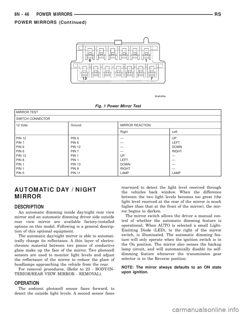
²Refer to the Mirror Test Chart for wire hookups
at the switch connector (Fig. 1).
(4) If results shown in table are not obtained,
check for broken or shorted circuit, or replace mirror
assembly as necessary.
RSPOWER MIRRORS8N-45
Page 2026 of 4284
AUTOMATIC DAY / NIGHT
MIRROR
DESCRIPTION
An automatic dimming inside day/night rear view
mirror and an automatic dimming driver side outside
rear view mirror are available factory-installed
options on this model. Following is a general descrip-
tion of this optional equipment.
The automatic day/night mirror is able to automat-
ically change its reflectance. A thin layer of electro-
chromic material between two pieces of conductive
glass make up the face of the mirror. Two photocell
sensors are used to monitor light levels and adjust
the reflectance of the mirror to reduce the glare of
headlamps approaching the vehicle from the rear.
For removal procedures, (Refer to 23 - BODY/IN-
TERIOR/REAR VIEW MIRROR - REMOVAL).
OPERATION
The ambient photocell sensor faces forward, to
detect the outside light levels. A second sensor facesrearward to detect the light level received through
the vehicles back window. When the difference
between the two light levels becomes too great (the
light level received at the rear of the mirror is much
higher than that at the front of the mirror), the mir-
ror begins to darken.
The mirror switch allows the driver a manual con-
trol of whether the automatic dimming feature is
operational. When AUTO is selected a small Light-
Emitting Diode (LED), to the right of the mirror
switch, is illuminated. The automatic dimming fea-
ture will only operate when the ignition switch is in
the On position. The mirror also senses the backup
lamp circuit, and will automatically disable its self-
dimming feature whenever the transmission gear
selector is in the Reverse position.
NOTE: The mirror always defaults to an ON state
upon ignition.
Fig. 1 Power Mirror Test
MIRROR TEST
SWITCH CONNECTOR
12 Volts Ground MIRROR REACTION
Right Left
PIN 12 PIN 6 Ð UP
PIN 7 PIN 6 Ð LEFT
PIN 6 PIN 12 Ð DOWN
PIN 6 PIN 7 Ð RIGHT
PIN 13 PIN 1 UP Ð
PIN 8 PIN 1 LEFT Ð
PIN 1 PIN 13 DOWN Ð
PIN 1 PIN 8 RIGHT Ð
PIN 5 PIN 11 LAMP LAMP
8N - 46 POWER MIRRORSRS
POWER MIRRORS (Continued)
Page 2027 of 4284
The driver side automatic dimming mirror is stan-
dard with the automatic dimming inside mirror. The
signal to control the dimming of that mirror is gen-
erated by the automatic day/night inside rear view
mirror circuitry. That signal is then delivered to the
driver side outside rear view mirror on a hard wired
circuit.
The automatic day/night mirror cannot be
repaired. If faulty or damaged, the entire inside rear
view mirror assembly must be replaced.
DIAGNOSIS AND TESTING - AUTOMATIC
DAY/NIGHT MIRROR
For circuit descriptions and diagrams, refer to the
appropriate wiring information. The wiring informa-
tion includes wiring diagrams, proper wire and con-
nector repair procedures, details of wire harness
routing and retention, connector pin-out information
and location views for the various wire harness con-
nectors, splices and grounds.
(1) Check the fuse in the intelligent power module.
If OK, go to Step 2. If not OK, repair the shorted cir-
cuit or component as required and replace the faulty
fuse.
(2) Turn the ignition switch to the On position.
Check for battery voltage at the fuse in the intelli-
gent power module. If OK, go to Step 3. If not OK,
repair the open circuit to the ignition switch as
required.
(3) Unplug the wire harness connector from the
automatic day/night mirror. Check for battery voltage
at the fused ignition switch output circuit cavity of
the automatic day/night mirror wire harness connec-
tor. If OK, go to Step 4. If not OK, repair the open
circuit to the junction block as required.
(4) Turn the ignition switch to the Off position.
Check for continuity between the ground circuit cav-
ity of the automatic day/night mirror wire harness
connector and a good ground. There should be conti-
nuity. If OK, go to Step 5. If not OK, repair the cir-
cuit to ground as required.
(5) Turn the ignition switch to the On position. Set
the parking brake. Place the transmission gear selec-
tor lever in the Reverse position. Check for battery
voltage at the backup lamp switch output circuit cav-ity of the automatic day/night mirror wire harness
connector. If voltage is present, reinstall the auto-
matic day/night mirror wire harness connector and
go to Step 6. If not OK, repair the open circuit as
required.
(6) Place the transmission gear selector lever in
the Neutral position. Place the automatic day/night
mirror switch in the On (LED in the switch is
lighted) position. Cover the forward facing ambient
photocell sensor to keep out any ambient light.
NOTE: The ambient photocell sensor must be cov-
ered completely, so that no light reaches the sen-
sor. Use a finger pressed tightly against the sensor,
or cover the sensor completely with electrical tape.
(7) Shine a light into the rearward facing head-
lamp photocell sensor. The automatic day/night mir-
ror should darken. The automatic day/night mirror
should darken within 2 minutes if testing for the
first time. For immediate response, turn the vehicle
OFF and back ON with the forward-facing light sen-
sor still covered. This defeats the day-detect logic. If
OK, go to Step 8. If not OK, replace the faulty mirror
unit.
(8) With the mirror darkened, place the transmis-
sion gear selector lever in the Reverse position. The
automatic day/night mirror should return to its nor-
mal reflectance. If not OK, replace the faulty mirror
unit.
Bench testing both mirrors can be done, of care is
exercised. For an inside mirror, the pin closest to he
mount is 12V (+), the next is 12V (-). The third is
reverse override. The fourth is outside mirror (+),
and the fifth is outside mirror (-).Do not apply 12
volts to the fourth and fifth pins.With 12 volts
on pins 1 and 2, the mirror can be tested by blocking
the rear sensor and shining a light into the forward
sensor. For an outside mirror, there is a 2±pin con-
nector. Applying 1.2 volts will cause the mirror to
dim. If the mirror does not dim, the entire glass
assembly can be replaced just as it is when the glass
is broken.
WARNING: Do not apply 12 volts to the outside mir-
ror. Damage to the mirror will result.
RSPOWER MIRRORS8N-47
AUTOMATIC DAY / NIGHT MIRROR (Continued)
Page 2040 of 4284
POWER WINDOWS
TABLE OF CONTENTS
page page
POWER WINDOWS
DESCRIPTION...........................60
OPERATION.............................60
DIAGNOSIS AND TESTING.................60
POWER WINDOWS.....................60
VENT WINDOW MOTOR
DIAGNOSIS AND TESTING.................61
VENT WINDOW MOTOR.................61
REMOVAL..............................61INSTALLATION...........................62
WINDOW MOTOR
REMOVAL..............................62
WINDOW SWITCH
DIAGNOSIS AND TESTING.................62
WINDOW SWITCH......................62
REMOVAL..............................63
INSTALLATION...........................63
POWER WINDOWS
DESCRIPTION
The Power Window System is activated through
switches mounted on the driver and passenger door
panels.
OPERATION
Front door window lift motors use permanent type
magnets. The B+ and ground applied at the motor ter-
minal pins will cause the motor to rotate in one direc-
tion. Reversing current through the motor terminals
will cause the motor to rotate in the opposite direction.
The power window motors ground through the
master switch in the driver door by a black wire
attached to the left cowl panel. Refer to the appropri-
ate wiring information. The wiring information
includes wiring diagrams, proper wire and connector
repair procedures, details of wire harness routing
and retention, connector pin-out information and
location views for the various wire harness connec-
tors, splices and grounds.
The power rear vent windows, if equipped, are oper-
ated by switches mounted in the driver door switch
bezel. A separate switch is used for each window. Per-
manent magnet type motors connected to a crank sys-
tem are used to open and close the rear vent windows.
A battery positive and negative connection to either of
the two motor terminals will cause the motor to rotate
in one direction. Reversing current through these same
two connections will cause the motor to rotate in the
opposite direction. Refer to the appropriate wiring infor-
mation. The wiring information includes wiring dia-
grams, proper wire and connector repair procedures,
details of wire harness routing and retention, connector
pin-out information and location views for the various
wire harness connectors, splices and grounds.
DIAGNOSIS AND TESTING - POWER
WINDOWS
POWER WINDOW MOTOR TEST
If the power window motor is receiving proper cur-
rent and ground and does not operate, proceed with
motor test. Refer to the appropriate wiring informa-
tion. The wiring information includes wiring dia-
grams, proper wire and connector repair procedures,
details of wire harness routing and retention, connec-
tor pin-out information and location views for the
various wire harness connectors, splices and grounds.
(1) Remove front door trim panel and sound pad as
necessary to gain access to power window motor wire
connector, (Refer to 23 - BODY/DOOR - FRONT/
TRIM PANEL - REMOVAL).
(2) Disconnect power window motor wire connector
from door harness.
(3) Using two jumper wires, connect one to a bat-
tery (+) source and the other to a good ground (-).
(4) Connect the Negative (-) jumper probe to one of
the motor connector terminals.
(5) Momentarily touch the Positive (+) jumper
probe to the other motor connector terminal.
When positive probe is connected the motor should
rotate in one direction to either move window up or
down. If window is all the way up or down the motor
will grunt and the inner door panel will flex when
actuated in that one direction.
(6) Reverse jumper probes at the motor connector
terminals and window should now move in opposite
direction. If window does not move or grunt, replace
the motor.
If window moved completely up or down, reverse
the jumper probes and cycle window to the opposite
position to verify full operation.
If motor grunts and does not move, verify that reg-
ulator is not binding.
8N - 60 POWER WINDOWSRS
Page 2648 of 4284

(6) Remove heater tube support bracket from cyl-
inder head.
(7) Disconnect radiator upper and heater supply
hoses from intake manifold water outlet connections.
(8) Remove accessory drive belts. (Refer to 7 -
COOLING/ACCESSORY DRIVE/DRIVE BELTS -
REMOVAL)
(9) Raise vehicle and remove exhaust pipe from
manifold.
(10) Remove power steering pump reservoir and
line support bracket from lower intake manifold and
set aside. Do not disconnect lines.
(11) Remove ignition coil and wires from engine.
(12) Disconnect cam sensor and fuel injector wir-
ing connectors.
(13) Remove timing belt and camshaft sprockets.
(Refer to 9 - ENGINE/VALVE TIMING/TIMING
BELT/CHAIN AND SPROCKETS - REMOVAL)
(14) Remove timing belt idler pulley and rear tim-
ing belt cover. (Refer to 9 - ENGINE/VALVE TIM-
ING/TIMING BELT / CHAIN COVER(S) -
REMOVAL)
(15) Remove cylinder head cover. (Refer to 9 -
ENGINE/CYLINDER HEAD/CYLINDER HEAD
COVER(S) - REMOVAL)
(16) Remove camshafts (Refer to 9 - ENGINE/
CYLINDER HEAD/CAMSHAFT(S) - REMOVAL).
NOTE: Identify rocker arm position to ensure cor-
rect re-installation in original position, if reused.
(17) Remove rocker arms. (Refer to 9 - ENGINE/
CYLINDER HEAD/ROCKER ARMS - REMOVAL)
(18) Remove cylinder head bolts in REVERSE
sequence of tightening (Fig. 19).
(19) Remove cylinder head from engine block.
(20) Inspect and clean cylinder head. (Refer to 9 -
ENGINE/CYLINDER HEAD - INSPECTION) (Refer
to 9 - ENGINE/CYLINDER HEAD - CLEANING)
CLEANING
To ensure engine gasket sealing, proper surface
preparation must be performed, especially with the
use of aluminum engine components and multi-layer
steel cylinder head gaskets.
NOTE: Multi-Layer Steel (MLS) head gaskets require
a scratch free sealing surface.
Remove all gasket material from cylinder head and
block. (Refer to 9 - ENGINE - STANDARD PROCE-
DURE) Be careful not to gouge or scratch the alumi-
num head sealing surface.
Clean all engine oil passages.
INSPECTION
(1) Cylinder head must be flat within 0.1 mm
(0.004 in.) (Fig. 14).
(2) Inspect camshaft bearing journals for scoring.
(3) Remove carbon and varnish deposits from
inside of valve guides with a reliable guide cleaner.
(4) Using a small hole gauge and a micrometer,
measure valve guides in 3 places top, middle and bot-
tom (Fig. 15). (Refer to 9 - ENGINE - SPECIFICA-
TIONS) Replace guides if they are not within
specification.
(5) Check valve guide height (Fig. 16).
INSTALLATION - CYLINDER HEAD
NOTE: The Cylinder head bolts should be examined
BEFORE reuse. If the threads are necked down, the
bolts must be replaced (Fig. 17).
Fig. 14 Checking Cylinder Head Flatness
1 - FEELER GAUGE
2 - STRAIGHT EDGE
Fig. 15 Checking Wear on Valve GuideÐTypical
1-TOP
2 - MIDDLE
3 - BOTTOM
4 - CUT AWAY VIEW OF VALVE GUIDE MEASUREMENT
LOCATIONS
9 - 24 ENGINE 2.4LRS
CYLINDER HEAD (Continued)
Page 2667 of 4284

(4) Pistons and connecting rods must be removed
from top of cylinder block. Rotate crankshaft so that
each connecting rod is centered in cylinder bore.
(5) Remove Balance Shaft Assembly. Refer to Bal-
ance Shaft Removal in this section.
(6) Remove connecting rod cap bolts. Push each
piston and rod assembly out of cylinder bore.NOTE: Be careful not to nick crankshaft journals.
(7) After removal, install bearing cap on the mat-
ing rod.
(8) Piston and Rods are serviced as an assembly.
INSTALLATION
(1) Before installing pistons and connecting rod
assemblies into the bore, be sure that compression
ring gaps are staggered so that neither is in line with
oil ring rail gap.
(2) Before installing the ring compressor, make
sure the oil ring expander ends are butted and the
rail gaps located as shown in (Fig. 68). As viewed
from top.
(3) Immerse the piston head and rings in clean
engine oil, slide the ring compressor, over the piston
(Fig. 69).Be sure position of rings does not
change during this operation.
(4) The directional stamp on the piston should face
toward the front of the engine (Fig. 66).
Fig. 65 Rear Crankshaft SealÐInstallation
1 - SPECIAL TOOL 6926±2 INSTALLER
Fig. 66 Piston Markings
1 - DIRECTIONAL ARROW WILL BE IMPRINTED IN THIS AREA
Fig. 67 Identify Connecting Rod to Cylinder
Fig. 68 Piston Ring End Gap Position
1 - GAP OF LOWER SIDE RAIL
2 - NO. 1 RING GAP
3 - GAP OF UPPER SIDE RAIL
4 - NO. 2 RING GAP AND SPACER EXPANDER GAP
RSENGINE 2.4L9-43
PISTON & CONNECTING ROD (Continued)
Page 2788 of 4284

(47) Remove left engine mount through bolt.
(48) Raise vehicle, leaving engine and transmis-
sion on engine cradle.
(49) Lift engine from engine cradle and diassemble
as necessary.
REMOVAL - ENGINE COVER
(1) Remove the engine cover retaining bolts.
(2) Remove the engine cover from the engine.
INSTALLATION - 2.5L TURBO DIESEL ENGINE
(1) Reassembly engine and transmission assembly
and install on engine cradle.
(2) Position engine and cradle assembly under
vehicle.
(3) Slowly lower the vehicle down over the engine
and cradle assembly.
(4) Install right engine mount bolts. Torque to
54N´m (40 ft. lbs.)
(5) Install left engine mount through bolt. Torque
to 75N´m (55 ft. lbs.)
(6) Raise vehicle and engine from engine cradle.
Fig. 9 ENGINE COMPONENT LOCATIONS
1 - FUEL INJECTOR RETURN LINE
2 - FUEL INJECTOR SUPPLY LINE
3 - OIL SEPARATOR
4 - FUEL INJECTOR
5 - CAMSHAFT POSITION SENSOR
6 - BOOST PRESSURE/INTAKE AIR TEMPERATURE SENSOR
7 - EGR SOLENOID
8 - FUEL PRESSURE SENSOR
9 - CYLINDER HEAD COVER/INTAKE MANIFOL
10 - FUEL RAIL
11 - WIRING HARNESS RETAINING CLIPS
Fig. 10 REAR ENGINE VIEW
1 - SUSPENSION CRADLE
2 - ENGINE BLOCK
3 - OIL PRESSURE SWITCH
4 - OIL TEMPERATURE SENSOR
5 - VEHICLE SPEED SENSOR
6 - TRANSMISSION
Fig. 11 Figure Caption Here
1 - ENGINE COVER MOUNTING BOLTS
2 - ENGINE COVER
9a - 6 ENGINE 2.5L TURBO DIESELRG
ENGINE 2.5L TURBO DIESEL (Continued)
Page 2831 of 4284

(7) Install timing belt (Refer to 9 - ENGINE/
VALVE TIMING/TIMING BELT/CHAIN AND
SPROCKETS - INSTALLATION) .
(8) Install timing belt outer cover (Refer to 9 -
ENGINE/VALVE TIMING/TIMING BELT / CHAIN
COVER(S) - INSTALLATION).
(9) Install accessory drive belt (Refer to 7 - COOL-
ING/ACCESSORY DRIVE/DRIVE BELTS - INSTAL-
LATION).
(10) Install power steering belt (Refer to 7 -
COOLING/ACCESSORY DRIVE/DRIVE BELTS -
INSTALLATION).
(11) Connect negative battery cable.
INSTALLATION
(1) Lubricate o-ring on oil pump pickup tube with
engine oil.
(2) Install pickup tube in engine block and install
retaining bolt (Fig. 71). Torque bolt to 32.4N´m.
(3) Install oil pan (Refer to 9 - ENGINE/LUBRI-
CATION/OIL PAN - INSTALLATION).
(4) Refill engine oil to proper level.
(5) Connect negative battery cable.
OIL PRESSURE SENSOR/
SWITCH
DESCRIPTION
The oil pressure switch is located on the right side
of the engine block. The switch screws into the
engines main oil gallery (Fig. 72).
REMOVAL
(1) Disconnect negative battery cable.
(2) Raise vehicle on hoist.
(3) Disconnect oil pressure switch electrical con-
nector (Fig. 72).
(4) Remove oil pressure switch from engine block.
Fig. 71 OIL PUMP PICKUP TUBE ASSEMBLY
1 - BALANCE SHAFT
2 - OIL JET RETAINING BOLT
3 - OIL JET
4 - ENGINE BLOCK
5 - CRANKSHAFT
6 - BALANCE SHAFT RETAINING BOLTS
7 - OIL DIPSTICK TUBE RETAINER
8 - RUBBER BUSHING
9 - RETAINING BOLT
Fig. 72 REAR ENGINE VIEW
1 - SUSPENSION CRADLE
2 - ENGINE BLOCK
3 - OIL PRESSURE SWITCH
4 - OIL TEMPERATURE SENSOR
5 - VEHICLE SPEED SENSOR
6 - TRANSMISSION
RGENGINE 2.5L TURBO DIESEL9a-49
OIL PUMP (Continued)
Page 2832 of 4284

INSTALLATION
(1) Apply MopartThread Sealant to the switch
threads.
(2) Install oil pressure switch in engine block.
(3) Connect oil pressure switch electrical connector
(Fig. 72).
(4) Lower vehicle.
(5) Start engine and check for leaks.
(6) Check and adjust oil level as necessary.
OIL TEMPERATURE SENSOR
DESCRIPTION
The oil temperature sensor is located on the right
side of the engine block. The sensor screws into the
engines main oil gallery (Fig. 73).
REMOVAL
(1) Disconnect negative battery cable.
(2) Raise vehicle on hoist.
(3) Disconnect oil temperature sensor electrical
connector (Fig. 73).
(4) Remove oil temperature sensor from engine
block.
INSTALLATION
(1) Apply MopartThread Sealant to the sensor
threads.
(2) Install oil temperature sensor in engine block.
(3) Connect oil temperature sensor electrical con-
nector (Fig. 73)
(4) Lower vehicle.
(5) Start engine and check for leaks.
(6) Check and adjust oil level as necessary.
OIL PRESSURE RELIEF VALVE
DESCRIPTION
The oil pressure relief valve mounts in the front of
the engine block and is used to control oil flow
through the engines lubrication system (Fig. 74).
Fig. 73 REAR ENGINE VIEW
1 - SUSPENSION CRADLE
2 - ENGINE BLOCK
3 - OIL PRESSURE SWITCH
4 - OIL TEMPERATURE SENSOR
5 - VEHICLE SPEED SENSOR
6 - TRANSMISSION
Fig. 74 OIL PRESSURE RELIEF VALVE
1 - O-RING
2 - OIL PRESSURE RELIEF VALVE CAP
3 - OIL PRESSURE RELIEF VALVE SPRING
4 - OIL PRESSURE RELIEF VALVE PLUNGER
9a - 50 ENGINE 2.5L TURBO DIESELRG
OIL PRESSURE SENSOR/SWITCH (Continued)