rear view CHRYSLER VOYAGER 2001 Owner's Manual
[x] Cancel search | Manufacturer: CHRYSLER, Model Year: 2001, Model line: VOYAGER, Model: CHRYSLER VOYAGER 2001Pages: 4284, PDF Size: 83.53 MB
Page 710 of 4284

TEST ACTION APPLICABILITY
4 If there are no possible causes remaining, view repair. All
Repair
Replace the Memory Seat Mirror Module.
Perform MEMORY SYSTEM VERIFICATION TEST - VER 1.
681
MEMORY SEAT
REAR RISER DOWN POSITION STUCK ÐContinued
Page 712 of 4284
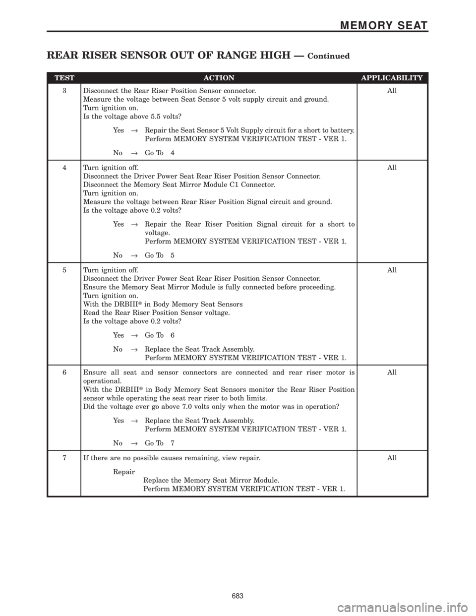
TEST ACTION APPLICABILITY
3 Disconnect the Rear Riser Position Sensor connector.
Measure the voltage between Seat Sensor 5 volt supply circuit and ground.
Turn ignition on.
Is the voltage above 5.5 volts?All
Ye s®Repair the Seat Sensor 5 Volt Supply circuit for a short to battery.
Perform MEMORY SYSTEM VERIFICATION TEST - VER 1.
No®Go To 4
4 Turn ignition off.
Disconnect the Driver Power Seat Rear Riser Position Sensor Connector.
Disconnect the Memory Seat Mirror Module C1 Connector.
Turn ignition on.
Measure the voltage between Rear Riser Position Signal circuit and ground.
Is the voltage above 0.2 volts?All
Ye s®Repair the Rear Riser Position Signal circuit for a short to
voltage.
Perform MEMORY SYSTEM VERIFICATION TEST - VER 1.
No®Go To 5
5 Turn ignition off.
Disconnect the Driver Power Seat Rear Riser Position Sensor Connector.
Ensure the Memory Seat Mirror Module is fully connected before proceeding.
Turn ignition on.
With the DRBIIItin Body Memory Seat Sensors
Read the Rear Riser Position Sensor voltage.
Is the voltage above 0.2 volts?All
Ye s®Go To 6
No®Replace the Seat Track Assembly.
Perform MEMORY SYSTEM VERIFICATION TEST - VER 1.
6 Ensure all seat and sensor connectors are connected and rear riser motor is
operational.
With the DRBIIItin Body Memory Seat Sensors monitor the Rear Riser Position
sensor while operating the seat rear riser to both limits.
Did the voltage ever go above 7.0 volts only when the motor was in operation?All
Ye s®Replace the Seat Track Assembly.
Perform MEMORY SYSTEM VERIFICATION TEST - VER 1.
No®Go To 7
7 If there are no possible causes remaining, view repair. All
Repair
Replace the Memory Seat Mirror Module.
Perform MEMORY SYSTEM VERIFICATION TEST - VER 1.
683
MEMORY SEAT
REAR RISER SENSOR OUT OF RANGE HIGH ÐContinued
Page 715 of 4284
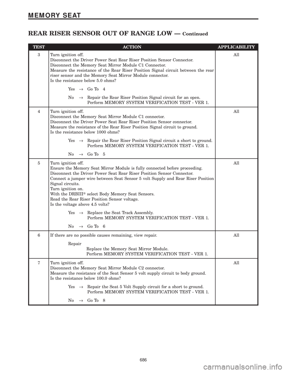
TEST ACTION APPLICABILITY
3 Turn ignition off.
Disconnect the Driver Power Seat Rear Riser Position Sensor Connector.
Disconnect the Memory Seat Mirror Module C1 Connector.
Measure the resistance of the Rear Riser Position Signal circuit between the rear
riser sensor and the Memory Seat Mirror Module connector.
Is the resistance below 5.0 ohms?All
Ye s®Go To 4
No®Repair the Rear Riser Position Signal circuit for an open.
Perform MEMORY SYSTEM VERIFICATION TEST - VER 1.
4 Turn ignition off.
Disconnect the Memory Seat Mirror Module C1 connector.
Disconnect the Driver Power Seat Rear Riser Position Sensor connector.
Measure the resistance of the Rear Riser Position Signal circuit to ground.
Is the resistance below 1000 ohms?All
Ye s®Repair the Rear Riser Position Signal circuit a short to ground.
Perform MEMORY SYSTEM VERIFICATION TEST - VER 1.
No®Go To 5
5 Turn ignition off.
Ensure the Memory Seat Mirror Module is fully connected before proceeding.
Disconnect the Driver Power Seat Rear Riser Position Sensor Connector.
Connect a jumper wire between Seat Sensor 5 volt Supply and Rear Riser Position
Signal circuits.
Turn ignition on.
With the DRBIIItselect Body Memory Seat Sensors.
Read the Rear Riser Position Sensor voltage.
Is the voltage above 4.5 volts?All
Ye s®Replace the Seat Track Assembly.
Perform MEMORY SYSTEM VERIFICATION TEST - VER 1.
No®Go To 6
6 If there are no possible causes remaining, view repair. All
Repair
Replace the Memory Seat Mirror Module.
Perform MEMORY SYSTEM VERIFICATION TEST - VER 1.
7 Turn ignition off.
Disconnect the Memory Seat Mirror Module C2 connector.
Measure the resistance of the Seat Sensor 5 volt supply circuit to body ground.
Is the resistance below 100.0 ohms?All
Ye s®Repair the Seat 5 Volt Supply circuit for a short to ground.
Perform MEMORY SYSTEM VERIFICATION TEST - VER 1.
No®Go To 8
686
MEMORY SEAT
REAR RISER SENSOR OUT OF RANGE LOW ÐContinued
Page 716 of 4284
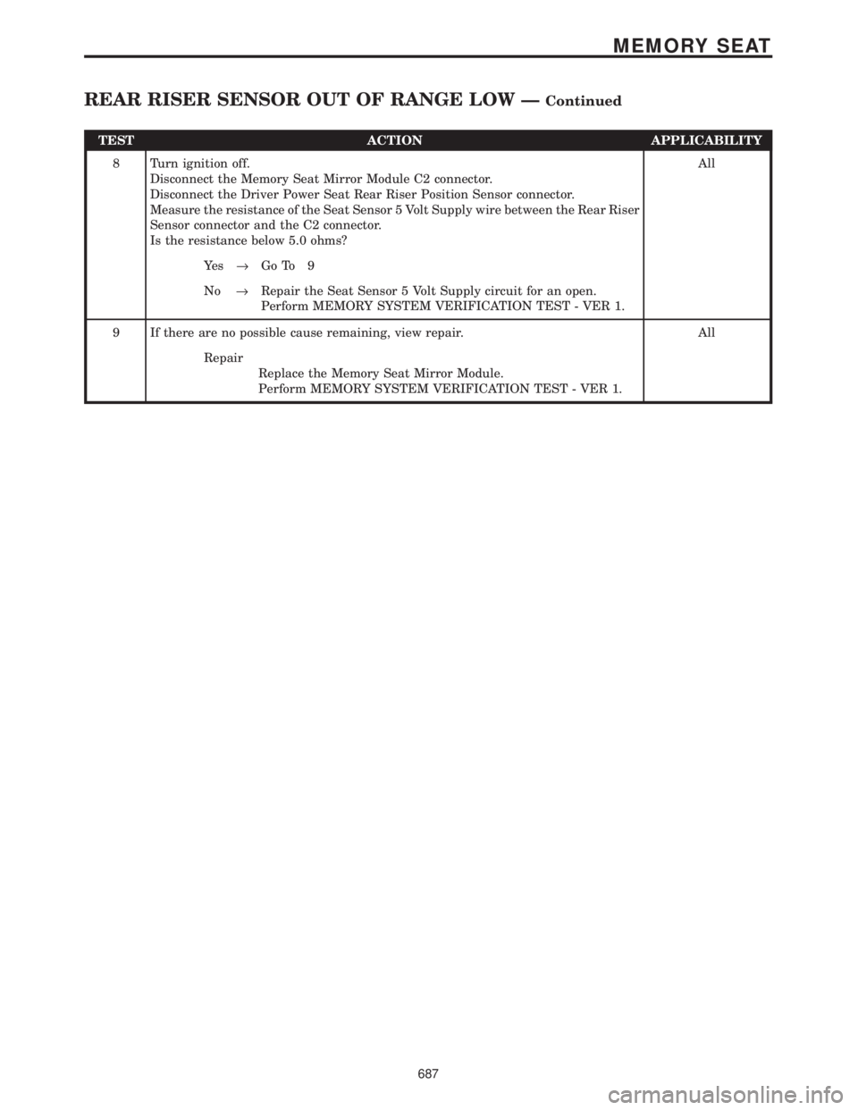
TEST ACTION APPLICABILITY
8 Turn ignition off.
Disconnect the Memory Seat Mirror Module C2 connector.
Disconnect the Driver Power Seat Rear Riser Position Sensor connector.
Measure the resistance of the Seat Sensor 5 Volt Supply wire between the Rear Riser
Sensor connector and the C2 connector.
Is the resistance below 5.0 ohms?All
Ye s®Go To 9
No®Repair the Seat Sensor 5 Volt Supply circuit for an open.
Perform MEMORY SYSTEM VERIFICATION TEST - VER 1.
9 If there are no possible cause remaining, view repair. All
Repair
Replace the Memory Seat Mirror Module.
Perform MEMORY SYSTEM VERIFICATION TEST - VER 1.
687
MEMORY SEAT
REAR RISER SENSOR OUT OF RANGE LOW ÐContinued
Page 718 of 4284

TEST ACTION APPLICABILITY
4 If there are no possible causes remaining, view repair. All
Repair
Replace the Memory Seat Mirror Module.
Perform MEMORY SYSTEM VERIFICATION TEST - VER 1.
689
MEMORY SEAT
REAR RISER UP POSITION STUCK ÐContinued
Page 1158 of 4284

1.0 INTRODUCTION
The procedures contained in this manual include
all the specifications, instructions, and graphics
needed to diagnose Mark 20 Antilock Braking Sys-
tem (ABS) and Mark 20 Antilock Braking System
with Traction Control. The diagnostics in this man-
ual are based on the failure condition or symptom
being present at time of diagnosis.
Please follow the recommendations below when
choosing your diagnostic path.
1. First make sure the DRBIIItis communicating
with the CAB. If the DRBIIItdisplays a ªNo
Responseº condition, you must diagnose that
first.
2. Read DTC's (diagnostic trouble codes) with the
DRBIIIt.
3. If no DTC's are present, identify the customer
complaint.
4. Once the DTC or customer complaint is identi-
fied, locate the matching test in the Table of
Contents and begin to diagnose the symptom.
All component location views are in Section 8.0.
All connector pinouts are in Section 9.0. All sche-
matics are in Section 10.0.
An * placed before the symptom description indi-
cates a concern with no associated DTC.
When repairs are required, refer to the appropri-
ate service manual for the proper removal and
repair procedure.
Diagnostic procedures change every year. New
diagnostic systems may be added; carry over sys-
tems may be enhanced. READ THIS MANUAL
BEFORE TRYING TO DIAGNOSE A VEHICLE
CODE. It is recommended that you review the
entire manual to become familiar with all new and
changed diagnostic procedures.
After using this book, if you have any comments
or recommendations, please fill out the form at the
back of the book and mail it back to us.
1.1 SYSTEM COVERAGE
This diagnostic procedure manual covers the an-
tilock braking system (ABS) and traction control
system found on: 2001 Chrysler Town and Country,
Dodge Caravan and Grand Caravan.
1.2 SIX-STEP TROUBLESHOOTING
PROCEDURE
Diagnosis of the controller antilock brake module
is done in six basic steps:
²verification of complaint
²verification of any related symptoms
²symptom analysis
²problem isolation
²repair of isolated problem
²verification of proper operation
2.0 IDENTIFICATION OF
SYSTEM
Vehicles equipped with the Teves Mark 20 an-
tilock brake system can be identified by the pres-
ence of the controller antilock brake module located
beneath the master cylinder.
3.0 SYSTEM DESCRIPTION AND
FUNCTIONAL OPERATION
3.1 TEVES MARK 20 SYSTEM
DESCRIPTION
The controller antilock brake module is used to
monitor wheel speeds and to modulate (control)
hydraulic pressure in each brake channel. The
modulated hydraulic pressure is used to prevent
wheel lock-up during braking.
The Teves Mark 20 system uses a diagonal split
hydraulic brake system.
In the standard brake mode
the master cylinder primary circuit supplies pressure
to the right front and left rear wheel brakes, and the
secondary master cylinder circuit supplies pressure
to the left front and right rear wheel brakes.
3.2 TRACTION CONTROL SYSTEM (TCS)
DESCRIPTION
The main purpose of traction control is to reduce
wheel slip and maintain traction at the driven
wheels when road surfaces are slippery. The trac-
tion control system reduces wheel slip by braking
the wheel that is losing traction. The system is
designed to operate at speeds below 56 km/h (35
mph).
The Controller Antilock Brake (CAB) monitors
wheel speeds. If, during acceleration, the module
detects front (drive) wheel slip and the brakes are
not applied, the CAB will enter traction control
mode. Traction control works in the following order
when drive wheel slip is detected.
1. Close the (normally open) isolation valves.
2. Start pump/motor and supply volume/pressure
to front hydraulic circuits (pump runs continu-
ously during traction control).
3. Open and close build and decay valves to main-
tain minimum wheel slip and maximum trac-
tion.
1
GENERAL INFORMATION
Page 1163 of 4284
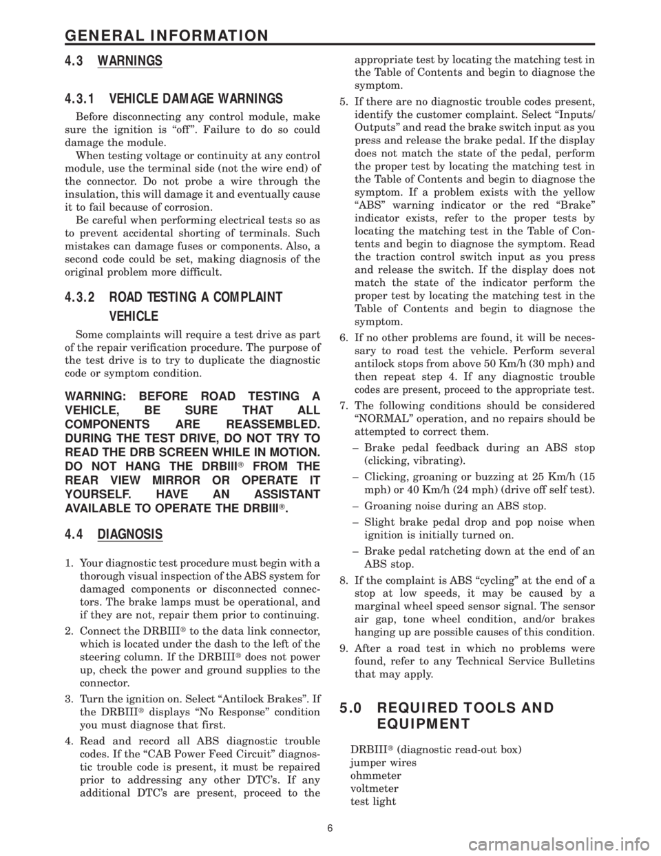
4.3 WARNINGS
4.3.1 VEHICLE DAMAGE WARNINGS
Before disconnecting any control module, make
sure the ignition is ``off ''. Failure to do so could
damage the module.
When testing voltage or continuity at any control
module, use the terminal side (not the wire end) of
the connector. Do not probe a wire through the
insulation, this will damage it and eventually cause
it to fail because of corrosion.
Be careful when performing electrical tests so as
to prevent accidental shorting of terminals. Such
mistakes can damage fuses or components. Also, a
second code could be set, making diagnosis of the
original problem more difficult.
4.3.2 ROAD TESTING A COMPLAINT
VEHICLE
Some complaints will require a test drive as part
of the repair verification procedure. The purpose of
the test drive is to try to duplicate the diagnostic
code or symptom condition.
WARNING: BEFORE ROAD TESTING A
VEHICLE, BE SURE THAT ALL
COMPONENTS ARE REASSEMBLED.
DURING THE TEST DRIVE, DO NOT TRY TO
READ THE DRB SCREEN WHILE IN MOTION.
DO NOT HANG THE DRBIIITFROM THE
REAR VIEW MIRROR OR OPERATE IT
YOURSELF. HAVE AN ASSISTANT
AVAILABLE TO OPERATE THE DRBIIIT.
4.4 DIAGNOSIS
1. Your diagnostic test procedure must begin with a
thorough visual inspection of the ABS system for
damaged components or disconnected connec-
tors. The brake lamps must be operational, and
if they are not, repair them prior to continuing.
2. Connect the DRBIIItto the data link connector,
which is located under the dash to the left of the
steering column. If the DRBIIItdoes not power
up, check the power and ground supplies to the
connector.
3. Turn the ignition on. Select ªAntilock Brakesº. If
the DRBIIItdisplays ªNo Responseº condition
you must diagnose that first.
4. Read and record all ABS diagnostic trouble
codes. If the ªCAB Power Feed Circuitº diagnos-
tic trouble code is present, it must be repaired
prior to addressing any other DTC's. If any
additional DTC's are present, proceed to theappropriate test by locating the matching test in
the Table of Contents and begin to diagnose the
symptom.
5. If there are no diagnostic trouble codes present,
identify the customer complaint. Select ªInputs/
Outputsº and read the brake switch input as you
press and release the brake pedal. If the display
does not match the state of the pedal, perform
the proper test by locating the matching test in
the Table of Contents and begin to diagnose the
symptom. If a problem exists with the yellow
ªABSº warning indicator or the red ªBrakeº
indicator exists, refer to the proper tests by
locating the matching test in the Table of Con-
tents and begin to diagnose the symptom. Read
the traction control switch input as you press
and release the switch. If the display does not
match the state of the indicator perform the
proper test by locating the matching test in the
Table of Contents and begin to diagnose the
symptom.
6. If no other problems are found, it will be neces-
sary to road test the vehicle. Perform several
antilock stops from above 50 Km/h (30 mph) and
then repeat step 4. If any diagnostic trouble
codes are present, proceed to the appropriate test.
7. The following conditions should be considered
ªNORMALº operation, and no repairs should be
attempted to correct them.
± Brake pedal feedback during an ABS stop
(clicking, vibrating).
± Clicking, groaning or buzzing at 25 Km/h (15
mph) or 40 Km/h (24 mph) (drive off self test).
± Groaning noise during an ABS stop.
± Slight brake pedal drop and pop noise when
ignition is initially turned on.
± Brake pedal ratcheting down at the end of an
ABS stop.
8. If the complaint is ABS ªcyclingº at the end of a
stop at low speeds, it may be caused by a
marginal wheel speed sensor signal. The sensor
air gap, tone wheel condition, and/or brakes
hanging up are possible causes of this condition.
9. After a road test in which no problems were
found, refer to any Technical Service Bulletins
that may apply.
5.0 REQUIRED TOOLS AND
EQUIPMENT
DRBIIIt(diagnostic read-out box)
jumper wires
ohmmeter
voltmeter
test light
6
GENERAL INFORMATION
Page 1227 of 4284

4.3 WARNINGS AND CAUTIONS
4.3.1 ROAD TEST WARNINGS
Some complaints will require a test drive as part
of the repair verification procedure. The purpose of
the test drive is to try to duplicate the diagnostic
code or symptom condition.
CAUTION: BEFORE ROAD TESTING A
VEHICLE, BE SURE THAT ALL
COMPONENTS ARE REASSEMBLED. DUR-
ING THE TEST DRIVE, DO NOT HANG THE
DRBIIITFROM THE REAR VIEW MIRROR. DO
NOT ATTEMPT TO READ THE DRBIIITWHILE
DRIVING. HAVE AN ASSISTANT AVAILABLE
TO OPERATE THE DRBIIIT.
4.3.2 VEHICLE DAMAGE CAUTIONS
Before disconnecting any control module, make
sure the ignition is off. Failure to do so could
damage the module. When testing voltage or circuit
integrity at any control module, use the terminal
side (not the wire end) of the harness connector. Do
not probe through the insulation; this will damage
it and eventually cause it to fail because of corro-
sion.
Be careful when performing electrical test so as to
prevent accidental shorting of terminals. Such a
mistake can damage fuses or components. Also, a
second code could be set, making diagnosis of the
original problem more difficult.
5.0 REQUIRED TOOLS AND
EQUIPMENT
DRBIIIt(diagnostic read-out box) scan tool
vacuum gauge
ammeter
ohmmeter
jumper wires and probes
oscilloscope
6.0 GLOSSARY OF TERMS
A/Cair conditioning
APPaccelerator pedal position (sensor)
backfire,
popbackfuel ignites in either the intake or
the exhaust system
BCMbody control module
BPboost pressure (sensor)CKPcrankshaft position (sensor)
CMPcamshaft position (sensor)
cuts out,
missesa steady pulsation or the inability of
the engine to maintain a consistent
rpm
DLCdata link connector
detona-
tion,
spark
knocka mild to severe ping, especially un-
der loaded engine conditions
ECMengine control module
ECTengine coolant temperature (sensor)
EGRexhaust gas recirculation
(solenoid/valve)
hard
startthe engine takes longer than usual
to start, even though it is able to
crank at normal speed.
IATintake air temperature (sensor)
IPMintelligent power module
lack of
power,
sluggishthe engine power output has been
reduced
MAFmass air flow (sensor)
MILmalfunction indicator lamp
msmillisecond(s)
PDCpower distribution center
poor fuel
economythere is significantly less fuel mile-
age than other vehicles of the same
design and configuration
runs
rough/
unstable
idlethe engine runs unevenly at idle
causing the engine to shake if it is
severe enough
S/Cspeed control
SKIMsentry key immobilizer module
SKISsentry key immobilizer system
start and
stallThe engine starts but immediately
dies (stalls)
surgeengine rpm fluctuation without cor-
responding change in accelerator
pedal position
SRCsignal range check
WIFwater in fuel (sensor)
VSSvehicle speed sensor
8
GENERAL INFORMATION
Page 1469 of 4284
INTRODUCTION
TABLE OF CONTENTS
page page
VEHICLE SAFETY CERTIFICATION LABEL
DESCRIPTION............................1
VEHICLE IDENTIFICATION NUMBER
DESCRIPTION............................1
VECI LABEL
DESCRIPTION............................3
BODY CODE PLATE
DESCRIPTION............................3
INTERNATIONAL SYMBOLS
DESCRIPTION............................4FASTENER IDENTIFICATION
DESCRIPTION............................5
FASTENER USAGE
DESCRIPTION............................5
METRIC SYSTEM
DESCRIPTION............................8
TORQUE REFERENCES
DESCRIPTION...........................10
VEHICLE SAFETY
CERTIFICATION LABEL
DESCRIPTION
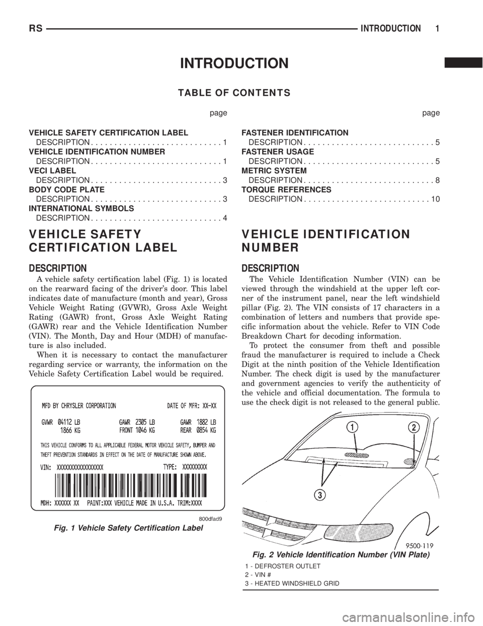
A vehicle safety certification label (Fig. 1) is located
on the rearward facing of the driver's door. This label
indicates date of manufacture (month and year), Gross
Vehicle Weight Rating (GVWR), Gross Axle Weight
Rating (GAWR) front, Gross Axle Weight Rating
(GAWR) rear and the Vehicle Identification Number
(VIN). The Month, Day and Hour (MDH) of manufac-
ture is also included.
When it is necessary to contact the manufacturer
regarding service or warranty, the information on the
Vehicle Safety Certification Label would be required.
VEHICLE IDENTIFICATION
NUMBER
DESCRIPTION
The Vehicle Identification Number (VIN) can be
viewed through the windshield at the upper left cor-
ner of the instrument panel, near the left windshield
pillar (Fig. 2). The VIN consists of 17 characters in a
combination of letters and numbers that provide spe-
cific information about the vehicle. Refer to VIN Code
Breakdown Chart for decoding information.
To protect the consumer from theft and possible
fraud the manufacturer is required to include a Check
Digit at the ninth position of the Vehicle Identification
Number. The check digit is used by the manufacturer
and government agencies to verify the authenticity of
the vehicle and official documentation. The formula to
use the check digit is not released to the general public.
Fig. 1 Vehicle Safety Certification Label
Fig. 2 Vehicle Identification Number (VIN Plate)
1 - DEFROSTER OUTLET
2 - VIN #
3 - HEATED WINDSHIELD GRID
RSINTRODUCTION1
Page 1505 of 4284
transmission in NEUTRAL and turn the ignition
OFF.
(3) On disabled vehicle, place gear selector in park
or neutral and set park brake. Turn off all accesso-
ries.
(4) Connect jumper cables to booster battery. RED
clamp to positive terminal (+). BLACK clamp to neg-
ative terminal (-). DO NOT allow clamps at opposite
end of cables to touch, electrical arc will result.
Review all warnings in this procedure.
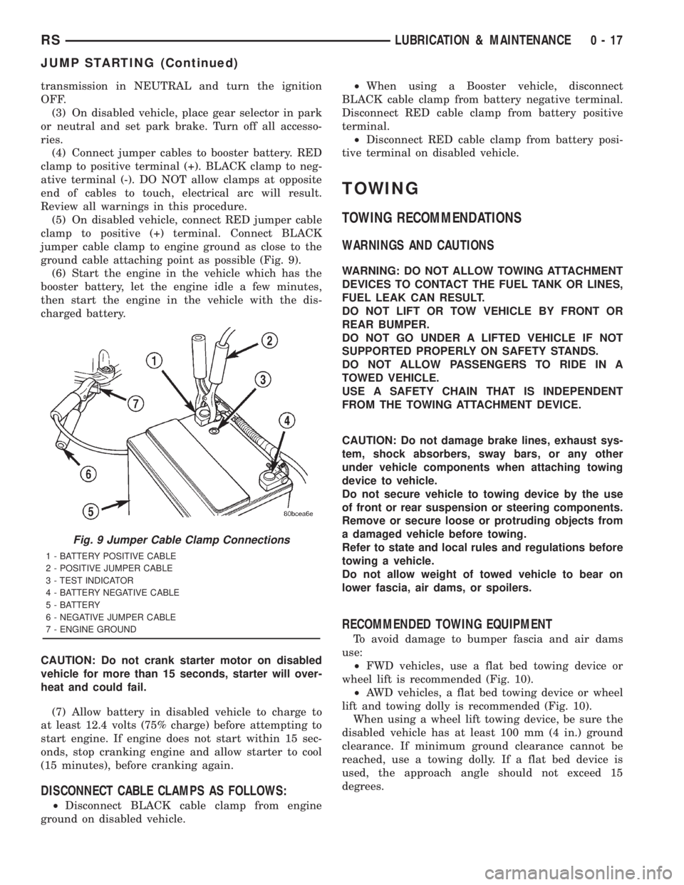
(5) On disabled vehicle, connect RED jumper cable
clamp to positive (+) terminal. Connect BLACK
jumper cable clamp to engine ground as close to the
ground cable attaching point as possible (Fig. 9).
(6) Start the engine in the vehicle which has the
booster battery, let the engine idle a few minutes,
then start the engine in the vehicle with the dis-
charged battery.
CAUTION: Do not crank starter motor on disabled
vehicle for more than 15 seconds, starter will over-
heat and could fail.
(7) Allow battery in disabled vehicle to charge to
at least 12.4 volts (75% charge) before attempting to
start engine. If engine does not start within 15 sec-
onds, stop cranking engine and allow starter to cool
(15 minutes), before cranking again.
DISCONNECT CABLE CLAMPS AS FOLLOWS:
²Disconnect BLACK cable clamp from engine
ground on disabled vehicle.²When using a Booster vehicle, disconnect
BLACK cable clamp from battery negative terminal.
Disconnect RED cable clamp from battery positive
terminal.
²Disconnect RED cable clamp from battery posi-
tive terminal on disabled vehicle.
TOWING
TOWING RECOMMENDATIONS
WARNINGS AND CAUTIONS
WARNING: DO NOT ALLOW TOWING ATTACHMENT
DEVICES TO CONTACT THE FUEL TANK OR LINES,
FUEL LEAK CAN RESULT.
DO NOT LIFT OR TOW VEHICLE BY FRONT OR
REAR BUMPER.
DO NOT GO UNDER A LIFTED VEHICLE IF NOT
SUPPORTED PROPERLY ON SAFETY STANDS.
DO NOT ALLOW PASSENGERS TO RIDE IN A
TOWED VEHICLE.
USE A SAFETY CHAIN THAT IS INDEPENDENT
FROM THE TOWING ATTACHMENT DEVICE.
CAUTION: Do not damage brake lines, exhaust sys-
tem, shock absorbers, sway bars, or any other
under vehicle components when attaching towing
device to vehicle.
Do not secure vehicle to towing device by the use
of front or rear suspension or steering components.
Remove or secure loose or protruding objects from
a damaged vehicle before towing.
Refer to state and local rules and regulations before
towing a vehicle.
Do not allow weight of towed vehicle to bear on
lower fascia, air dams, or spoilers.
RECOMMENDED TOWING EQUIPMENT
To avoid damage to bumper fascia and air dams
use:
²FWD vehicles, use a flat bed towing device or
wheel lift is recommended (Fig. 10).
²AWD vehicles, a flat bed towing device or wheel
lift and towing dolly is recommended (Fig. 10).
When using a wheel lift towing device, be sure the
disabled vehicle has at least 100 mm (4 in.) ground
clearance. If minimum ground clearance cannot be
reached, use a towing dolly. If a flat bed device is
used, the approach angle should not exceed 15
degrees.
Fig. 9 Jumper Cable Clamp Connections
1 - BATTERY POSITIVE CABLE
2 - POSITIVE JUMPER CABLE
3 - TEST INDICATOR
4 - BATTERY NEGATIVE CABLE
5 - BATTERY
6 - NEGATIVE JUMPER CABLE
7 - ENGINE GROUND
RSLUBRICATION & MAINTENANCE0-17
JUMP STARTING (Continued)