CHRYSLER VOYAGER 2001 Service Manual
Manufacturer: CHRYSLER, Model Year: 2001, Model line: VOYAGER, Model: CHRYSLER VOYAGER 2001Pages: 4284, PDF Size: 83.53 MB
Page 891 of 4284
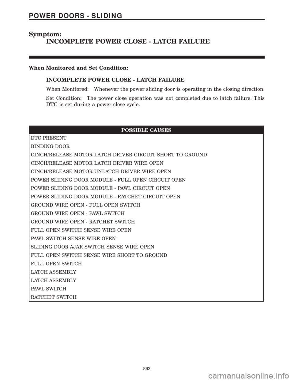
Symptom:
INCOMPLETE POWER CLOSE - LATCH FAILURE
When Monitored and Set Condition:
INCOMPLETE POWER CLOSE - LATCH FAILURE
When Monitored: Whenever the power sliding door is operating in the closing direction.
Set Condition: The power close operation was not completed due to latch failure. This
DTC is set during a power close cycle.
POSSIBLE CAUSES
DTC PRESENT
BINDING DOOR
CINCH/RELEASE MOTOR LATCH DRIVER CIRCUIT SHORT TO GROUND
CINCH/RELEASE MOTOR LATCH DRIVER WIRE OPEN
CINCH/RELEASE MOTOR UNLATCH DRIVER WIRE OPEN
POWER SLIDING DOOR MODULE - FULL OPEN CIRCUIT OPEN
POWER SLIDING DOOR MODULE - PAWL CIRCUIT OPEN
POWER SLIDING DOOR MODULE - RATCHET CIRCUIT OPEN
GROUND WIRE OPEN - FULL OPEN SWITCH
GROUND WIRE OPEN - PAWL SWITCH
GROUND WIRE OPEN - RATCHET SWITCH
FULL OPEN SWITCH SENSE WIRE OPEN
PAWL SWITCH SENSE WIRE OPEN
SLIDING DOOR AJAR SWITCH SENSE WIRE OPEN
FULL OPEN SWITCH SENSE WIRE SHORT TO GROUND
FULL OPEN SWITCH
LATCH ASSEMBLY
LATCH ASSEMBLY
PAWL SWITCH
RATCHET SWITCH
862
POWER DOORS - SLIDING
Page 892 of 4284
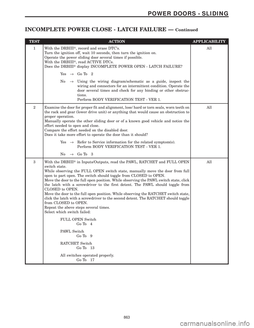
TEST ACTION APPLICABILITY
1 With the DRBIIIt, record and erase DTC's.
Turn the ignition off, wait 10 seconds, then turn the ignition on.
Operate the power sliding door several times if possible.
With the DRBIIIt, read ACTIVE DTCs.
Does the DRBIIItdisplay INCOMPLETE POWER OPEN - LATCH FAILURE?All
Ye s®Go To 2
No®Using the wiring diagram/schematic as a guide, inspect the
wiring and connectors for an intermittent condition. Operate the
door several times and check for any binding or other obstruc-
tions.
Perform BODY VERIFICATION TEST - VER 1.
2 Examine the door for proper fit and alignment, lose/ hard or torn seals, worn teeth on
the rack and gear (lower drive unit) or anything that would cause an obstruction to
proper operation.
Manually operate the other sliding door or of a known good vehicle and notice the
effort needed to open and close.
Compare the effort needed on the disabled door.
Does it take more effort to operate the door than it should?All
Ye s®Refer to Service information for the related symptom(s).
Perform BODY VERIFICATION TEST - VER 1.
No®Go To 3
3 With the DRBIIItin Inputs/Outputs, read the PAWL, RATCHET and FULL OPEN
switch state.
While observing the FULL OPEN switch state, manually move the door from full
open to part open. The switch should toggle from CLOSED to OPEN.
Move the door to the full open position. While observing the PAWL switch state, click
the latch with a screwdriver to the first detent. The PAWL should toggle from
CLOSED to OPEN.
Move the door to the full open position. While observing the RATCHET switch state,
click the latch with a screwdriver to the second detent. The RATCHET should toggle
from CLOSED to OPEN.
Repeat the above steps several times.
Select which switch failed:All
FULL OPEN Switch
Go To 4
PAWL Switch
Go To 9
RATCHET Switch
Go To 13
All switches operated properly.
Go To 17
863
POWER DOORS - SLIDING
INCOMPLETE POWER CLOSE - LATCH FAILURE ÐContinued
Page 893 of 4284
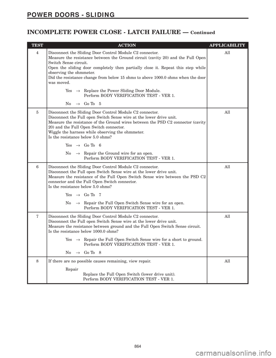
TEST ACTION APPLICABILITY
4 Disconnect the Sliding Door Control Module C2 connector.
Measure the resistance between the Ground circuit (cavity 20) and the Full Open
Switch Sense circuit.
Open the sliding door completely then partially close it. Repeat this step while
observing the ohmmeter.
Did the resistance change from below 15 ohms to above 1000.0 ohms when the door
was moved.All
Ye s®Replace the Power Sliding Door Module.
Perform BODY VERIFICATION TEST - VER 1.
No®Go To 5
5 Disconnect the Sliding Door Control Module C2 connector.
Disconnect the Full open Switch Sense wire at the lower drive unit.
Measure the resistance of the Ground wires between the PSD C2 connector (cavity
20) and the Full Open Switch connector.
Wiggle the harness while observing the ohmmeter.
Is the resistance below 5.0 ohms?All
Ye s®Go To 6
No®Repair the Ground wire for an open.
Perform BODY VERIFICATION TEST - VER 1.
6 Disconnect the Sliding Door Control Module C2 connector.
Disconnect the Full open Switch Sense wire at the lower drive unit.
Measure the resistance of the Full Open Switch Sense wire between the PSD C2
connector and the Full Open Switch connector.
Is the resistance below 5.0 ohms?All
Ye s®Go To 7
No®Repair the Full Open Switch Sense wire for an open.
Perform BODY VERIFICATION TEST - VER 1.
7 Disconnect the Sliding Door Control Module C2 connector.
Disconnect the Full open Switch Sense wire at the lower drive unit.
Measure the resistance between ground and the Full Open Switch Sense circuit.
Is the resistance below 1000.0 ohms?All
Ye s®Repair the Full Open Switch Sense wire for a short to ground.
Perform BODY VERIFICATION TEST - VER 1.
No®Go To 8
8 If there are no possible causes remaining, view repair. All
Repair
Replace the Full Open Switch (lower drive unit).
Perform BODY VERIFICATION TEST - VER 1.
864
POWER DOORS - SLIDING
INCOMPLETE POWER CLOSE - LATCH FAILURE ÐContinued
Page 894 of 4284
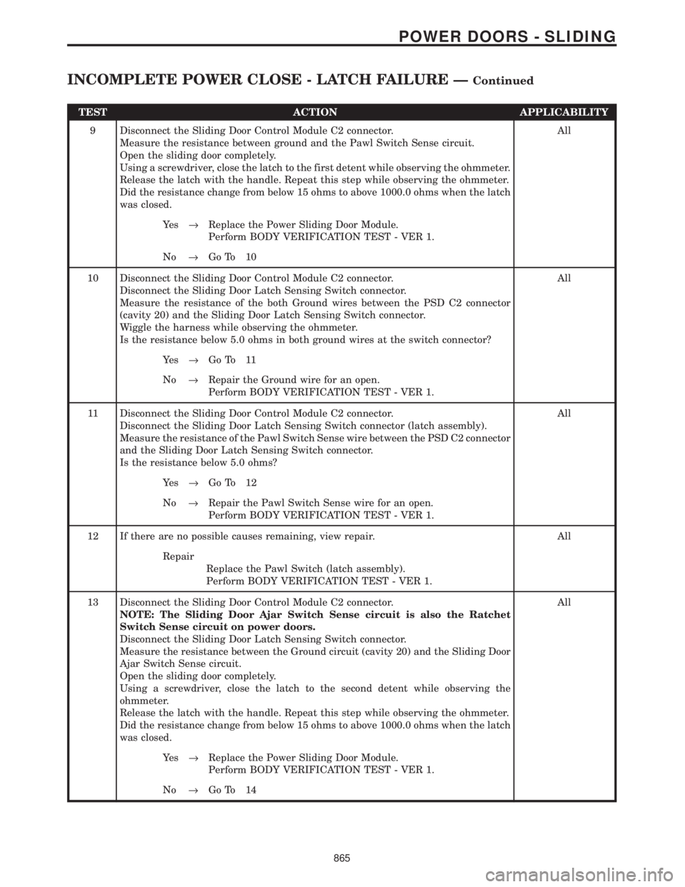
TEST ACTION APPLICABILITY
9 Disconnect the Sliding Door Control Module C2 connector.
Measure the resistance between ground and the Pawl Switch Sense circuit.
Open the sliding door completely.
Using a screwdriver, close the latch to the first detent while observing the ohmmeter.
Release the latch with the handle. Repeat this step while observing the ohmmeter.
Did the resistance change from below 15 ohms to above 1000.0 ohms when the latch
was closed.All
Ye s®Replace the Power Sliding Door Module.
Perform BODY VERIFICATION TEST - VER 1.
No®Go To 10
10 Disconnect the Sliding Door Control Module C2 connector.
Disconnect the Sliding Door Latch Sensing Switch connector.
Measure the resistance of the both Ground wires between the PSD C2 connector
(cavity 20) and the Sliding Door Latch Sensing Switch connector.
Wiggle the harness while observing the ohmmeter.
Is the resistance below 5.0 ohms in both ground wires at the switch connector?All
Ye s®Go To 11
No®Repair the Ground wire for an open.
Perform BODY VERIFICATION TEST - VER 1.
11 Disconnect the Sliding Door Control Module C2 connector.
Disconnect the Sliding Door Latch Sensing Switch connector (latch assembly).
Measure the resistance of the Pawl Switch Sense wire between the PSD C2 connector
and the Sliding Door Latch Sensing Switch connector.
Is the resistance below 5.0 ohms?All
Ye s®Go To 12
No®Repair the Pawl Switch Sense wire for an open.
Perform BODY VERIFICATION TEST - VER 1.
12 If there are no possible causes remaining, view repair. All
Repair
Replace the Pawl Switch (latch assembly).
Perform BODY VERIFICATION TEST - VER 1.
13 Disconnect the Sliding Door Control Module C2 connector.
NOTE: The Sliding Door Ajar Switch Sense circuit is also the Ratchet
Switch Sense circuit on power doors.
Disconnect the Sliding Door Latch Sensing Switch connector.
Measure the resistance between the Ground circuit (cavity 20) and the Sliding Door
Ajar Switch Sense circuit.
Open the sliding door completely.
Using a screwdriver, close the latch to the second detent while observing the
ohmmeter.
Release the latch with the handle. Repeat this step while observing the ohmmeter.
Did the resistance change from below 15 ohms to above 1000.0 ohms when the latch
was closed.All
Ye s®Replace the Power Sliding Door Module.
Perform BODY VERIFICATION TEST - VER 1.
No®Go To 14
865
POWER DOORS - SLIDING
INCOMPLETE POWER CLOSE - LATCH FAILURE ÐContinued
Page 895 of 4284
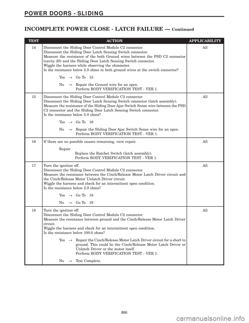
TEST ACTION APPLICABILITY
14 Disconnect the Sliding Door Control Module C2 connector.
Disconnect the Sliding Door Latch Sensing Switch connector.
Measure the resistance of the both Ground wires between the PSD C2 connector
(cavity 20) and the Sliding Door Latch Sensing Switch connector.
Wiggle the harness while observing the ohmmeter.
Is the resistance below 5.0 ohms in both ground wires at the switch connector?All
Ye s®Go To 15
No®Repair the Ground wire for an open.
Perform BODY VERIFICATION TEST - VER 1.
15 Disconnect the Sliding Door Control Module C2 connector.
Disconnect the Sliding Door Latch Sensing Switch connector (latch assembly).
Measure the resistance of the Sliding Door Ajar Switch Sense wire between the PSD
C2 connector and the Sliding Door Latch Sensing Switch connector.
Is the resistance below 5.0 ohms?All
Ye s®Go To 16
No®Repair the Sliding Door Ajar Switch Sense wire for an open.
Perform BODY VERIFICATION TEST - VER 1.
16 If there are no possible causes remaining, view repair. All
Repair
Replace the Ratchet Switch (latch assembly).
Perform BODY VERIFICATION TEST - VER 1.
17 Turn the ignition off.
Disconnect the Sliding Door Control Module C2 connector.
Measure the resistance between the Cinch/Release Motor Latch Driver circuit and
the Cinch/Release Motor Unlatch Driver circuit.
Wiggle the harness and check for an intermittent open condition.
Is the resistance below 2.0 ohms?All
Ye s®Go To 18
No®Go To 19
18 Turn the ignition off.
Disconnect the Sliding Door Control Module C2 connector.
Measure the resistance between ground and the Cinch/Release Motor Latch Driver
circuit.
Wiggle the harness and check for an intermittent open condition.
Is the resistance below 100.0 ohms?All
Ye s®Repair the Cinch/Release Motor Latch Driver circuit for a short to
ground. This could be the Cinch/Release Motor Latch Driver or
Unlatch Driver or the motor itself.
Perform BODY VERIFICATION TEST - VER 1.
No®Test Complete.
866
POWER DOORS - SLIDING
INCOMPLETE POWER CLOSE - LATCH FAILURE ÐContinued
Page 896 of 4284
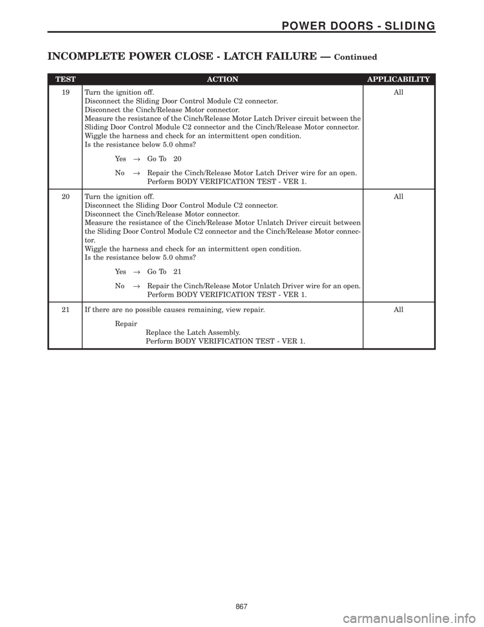
TEST ACTION APPLICABILITY
19 Turn the ignition off.
Disconnect the Sliding Door Control Module C2 connector.
Disconnect the Cinch/Release Motor connector.
Measure the resistance of the Cinch/Release Motor Latch Driver circuit between the
Sliding Door Control Module C2 connector and the Cinch/Release Motor connector.
Wiggle the harness and check for an intermittent open condition.
Is the resistance below 5.0 ohms?All
Ye s®Go To 20
No®Repair the Cinch/Release Motor Latch Driver wire for an open.
Perform BODY VERIFICATION TEST - VER 1.
20 Turn the ignition off.
Disconnect the Sliding Door Control Module C2 connector.
Disconnect the Cinch/Release Motor connector.
Measure the resistance of the Cinch/Release Motor Unlatch Driver circuit between
the Sliding Door Control Module C2 connector and the Cinch/Release Motor connec-
tor.
Wiggle the harness and check for an intermittent open condition.
Is the resistance below 5.0 ohms?All
Ye s®Go To 21
No®Repair the Cinch/Release Motor Unlatch Driver wire for an open.
Perform BODY VERIFICATION TEST - VER 1.
21 If there are no possible causes remaining, view repair. All
Repair
Replace the Latch Assembly.
Perform BODY VERIFICATION TEST - VER 1.
867
POWER DOORS - SLIDING
INCOMPLETE POWER CLOSE - LATCH FAILURE ÐContinued
Page 897 of 4284
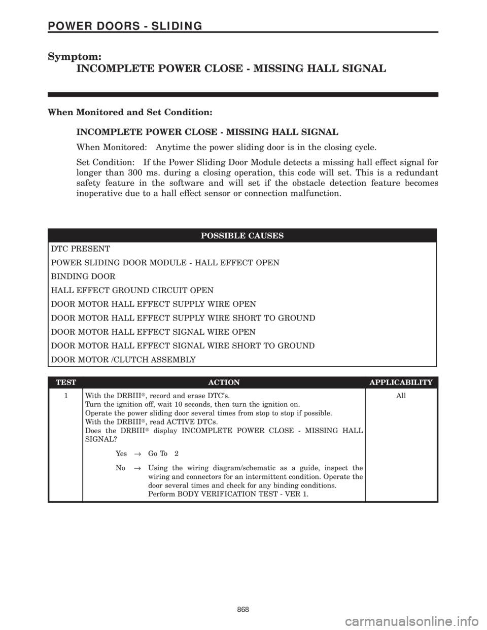
Symptom:
INCOMPLETE POWER CLOSE - MISSING HALL SIGNAL
When Monitored and Set Condition:
INCOMPLETE POWER CLOSE - MISSING HALL SIGNAL
When Monitored: Anytime the power sliding door is in the closing cycle.
Set Condition: If the Power Sliding Door Module detects a missing hall effect signal for
longer than 300 ms. during a closing operation, this code will set. This is a redundant
safety feature in the software and will set if the obstacle detection feature becomes
inoperative due to a hall effect sensor or connection malfunction.
POSSIBLE CAUSES
DTC PRESENT
POWER SLIDING DOOR MODULE - HALL EFFECT OPEN
BINDING DOOR
HALL EFFECT GROUND CIRCUIT OPEN
DOOR MOTOR HALL EFFECT SUPPLY WIRE OPEN
DOOR MOTOR HALL EFFECT SUPPLY WIRE SHORT TO GROUND
DOOR MOTOR HALL EFFECT SIGNAL WIRE OPEN
DOOR MOTOR HALL EFFECT SIGNAL WIRE SHORT TO GROUND
DOOR MOTOR /CLUTCH ASSEMBLY
TEST ACTION APPLICABILITY
1 With the DRBIIIt, record and erase DTC's.
Turn the ignition off, wait 10 seconds, then turn the ignition on.
Operate the power sliding door several times from stop to stop if possible.
With the DRBIIIt, read ACTIVE DTCs.
Does the DRBIIItdisplay INCOMPLETE POWER CLOSE - MISSING HALL
SIGNAL?All
Ye s®Go To 2
No®Using the wiring diagram/schematic as a guide, inspect the
wiring and connectors for an intermittent condition. Operate the
door several times and check for any binding conditions.
Perform BODY VERIFICATION TEST - VER 1.
868
POWER DOORS - SLIDING
Page 898 of 4284
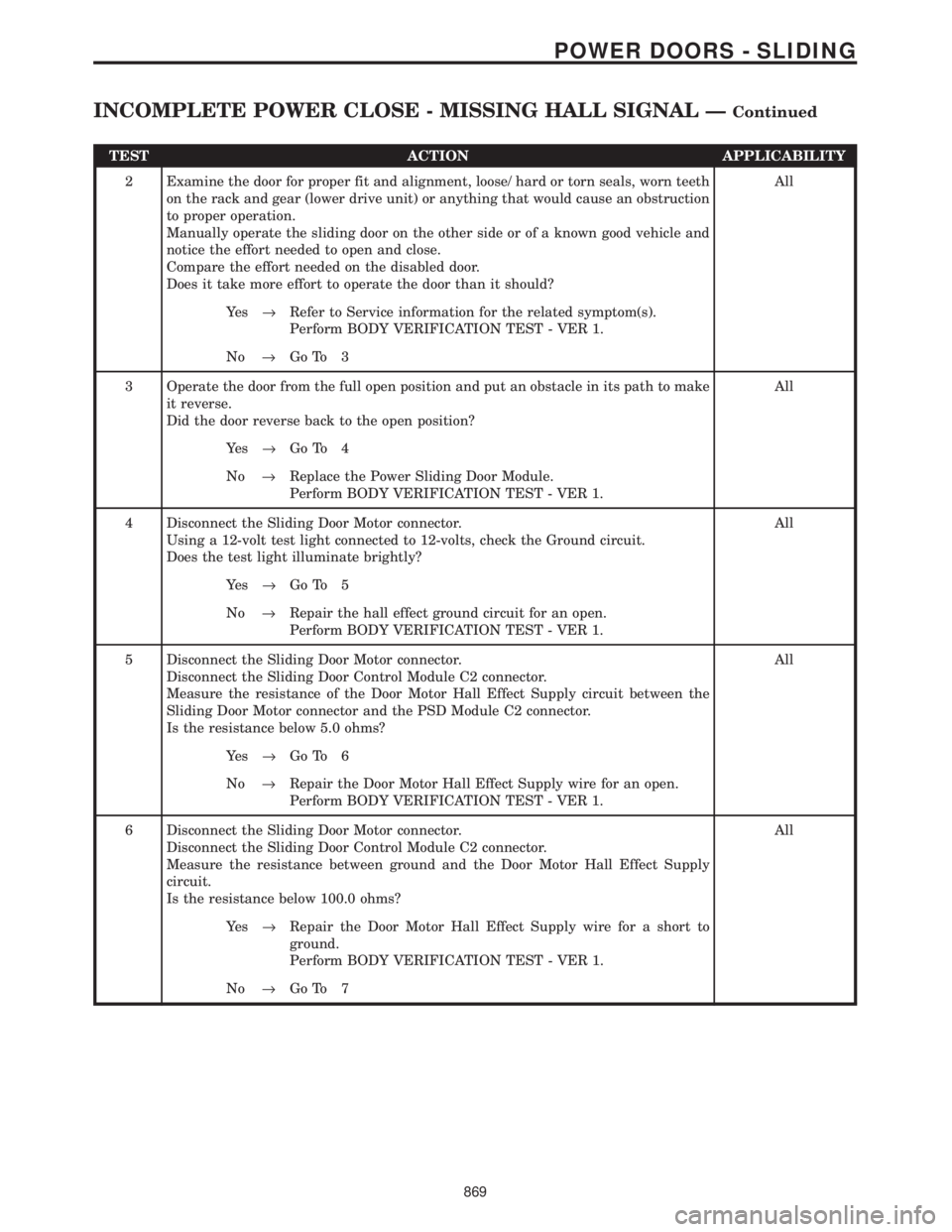
TEST ACTION APPLICABILITY
2 Examine the door for proper fit and alignment, loose/ hard or torn seals, worn teeth
on the rack and gear (lower drive unit) or anything that would cause an obstruction
to proper operation.
Manually operate the sliding door on the other side or of a known good vehicle and
notice the effort needed to open and close.
Compare the effort needed on the disabled door.
Does it take more effort to operate the door than it should?All
Ye s®Refer to Service information for the related symptom(s).
Perform BODY VERIFICATION TEST - VER 1.
No®Go To 3
3 Operate the door from the full open position and put an obstacle in its path to make
it reverse.
Did the door reverse back to the open position?All
Ye s®Go To 4
No®Replace the Power Sliding Door Module.
Perform BODY VERIFICATION TEST - VER 1.
4 Disconnect the Sliding Door Motor connector.
Using a 12-volt test light connected to 12-volts, check the Ground circuit.
Does the test light illuminate brightly?All
Ye s®Go To 5
No®Repair the hall effect ground circuit for an open.
Perform BODY VERIFICATION TEST - VER 1.
5 Disconnect the Sliding Door Motor connector.
Disconnect the Sliding Door Control Module C2 connector.
Measure the resistance of the Door Motor Hall Effect Supply circuit between the
Sliding Door Motor connector and the PSD Module C2 connector.
Is the resistance below 5.0 ohms?All
Ye s®Go To 6
No®Repair the Door Motor Hall Effect Supply wire for an open.
Perform BODY VERIFICATION TEST - VER 1.
6 Disconnect the Sliding Door Motor connector.
Disconnect the Sliding Door Control Module C2 connector.
Measure the resistance between ground and the Door Motor Hall Effect Supply
circuit.
Is the resistance below 100.0 ohms?All
Ye s®Repair the Door Motor Hall Effect Supply wire for a short to
ground.
Perform BODY VERIFICATION TEST - VER 1.
No®Go To 7
869
POWER DOORS - SLIDING
INCOMPLETE POWER CLOSE - MISSING HALL SIGNAL ÐContinued
Page 899 of 4284
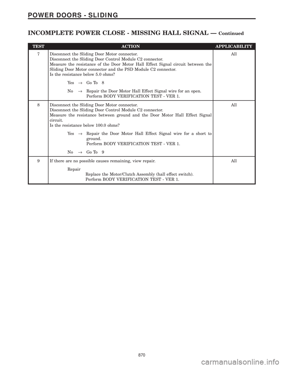
TEST ACTION APPLICABILITY
7 Disconnect the Sliding Door Motor connector.
Disconnect the Sliding Door Control Module C2 connector.
Measure the resistance of the Door Motor Hall Effect Signal circuit between the
Sliding Door Motor connector and the PSD Module C2 connector.
Is the resistance below 5.0 ohms?All
Ye s®Go To 8
No®Repair the Door Motor Hall Effect Signal wire for an open.
Perform BODY VERIFICATION TEST - VER 1.
8 Disconnect the Sliding Door Motor connector.
Disconnect the Sliding Door Control Module C2 connector.
Measure the resistance between ground and the Door Motor Hall Effect Signal
circuit.
Is the resistance below 100.0 ohms?All
Ye s®Repair the Door Motor Hall Effect Signal wire for a short to
ground.
Perform BODY VERIFICATION TEST - VER 1.
No®Go To 9
9 If there are no possible causes remaining, view repair. All
Repair
Replace the Motor/Clutch Assembly (hall effect switch).
Perform BODY VERIFICATION TEST - VER 1.
870
POWER DOORS - SLIDING
INCOMPLETE POWER CLOSE - MISSING HALL SIGNAL ÐContinued
Page 900 of 4284
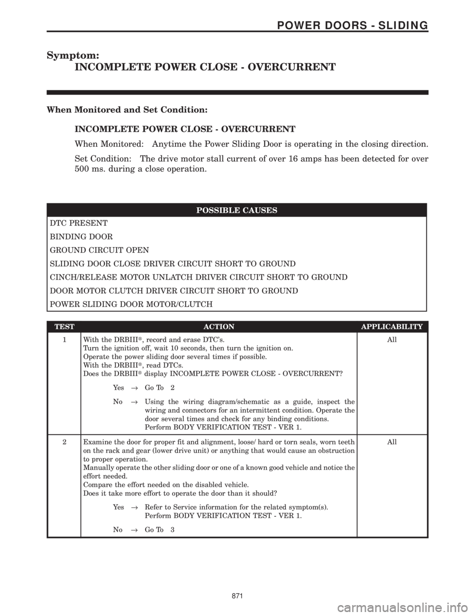
Symptom:
INCOMPLETE POWER CLOSE - OVERCURRENT
When Monitored and Set Condition:
INCOMPLETE POWER CLOSE - OVERCURRENT
When Monitored: Anytime the Power Sliding Door is operating in the closing direction.
Set Condition: The drive motor stall current of over 16 amps has been detected for over
500 ms. during a close operation.
POSSIBLE CAUSES
DTC PRESENT
BINDING DOOR
GROUND CIRCUIT OPEN
SLIDING DOOR CLOSE DRIVER CIRCUIT SHORT TO GROUND
CINCH/RELEASE MOTOR UNLATCH DRIVER CIRCUIT SHORT TO GROUND
DOOR MOTOR CLUTCH DRIVER CIRCUIT SHORT TO GROUND
POWER SLIDING DOOR MOTOR/CLUTCH
TEST ACTION APPLICABILITY
1 With the DRBIIIt, record and erase DTC's.
Turn the ignition off, wait 10 seconds, then turn the ignition on.
Operate the power sliding door several times if possible.
With the DRBIIIt, read DTCs.
Does the DRBIIItdisplay INCOMPLETE POWER CLOSE - OVERCURRENT?All
Ye s®Go To 2
No®Using the wiring diagram/schematic as a guide, inspect the
wiring and connectors for an intermittent condition. Operate the
door several times and check for any binding conditions.
Perform BODY VERIFICATION TEST - VER 1.
2 Examine the door for proper fit and alignment, loose/ hard or torn seals, worn teeth
on the rack and gear (lower drive unit) or anything that would cause an obstruction
to proper operation.
Manually operate the other sliding door or one of a known good vehicle and notice the
effort needed.
Compare the effort needed on the disabled vehicle.
Does it take more effort to operate the door than it should?All
Ye s®Refer to Service information for the related symptom(s).
Perform BODY VERIFICATION TEST - VER 1.
No®Go To 3
871
POWER DOORS - SLIDING