CHRYSLER VOYAGER 2002 Service Manual
Manufacturer: CHRYSLER, Model Year: 2002, Model line: VOYAGER, Model: CHRYSLER VOYAGER 2002Pages: 2399, PDF Size: 57.96 MB
Page 1561 of 2399

FLUID LEAK DIAGNOSIS
When diagnosing fluid leaks on the Power Transfer
Unit two weep holes are provided to diagnose certain
seal leaks. These holes are located on the bottom side
of the assembly (Fig. 5).
If fluid leak is detected from either weep hole, seal
replacement is necessary.Do not attempt to repair
the leak by sealing weep holes,they must be kept
clear of sealants for proper seal operation.
If fluid is leaking from weep hole A (Fig. 5) the
type of fluid leaking will determine which seal needs
to be replaced. If the fluid leaking is red in color(transmission fluid) this indicates that the Transmis-
sion differential carrier seal should be replaced. If
the fluid leaking is light brown (gear lube) this indi-
cates that the Power Transfer Unit input seal should
be replaced. For replacement of these seals refer to
Power Transfer Unit Service Procedures.
If fluid is leaking from weep hole B (Fig. 5) the
type of fluid leaking will determine which seal is
leaking. If the fluid leaking is red in color (transmis-
sion fluid) this indicates that the input shaft end seal
should be replaced. If the fluid leaking is light brown
(gear lube) this indicates that the half shaft inner
seal and P.T.U. input shaft cover seal should be
replaced. For replacement of these seals refer to
Power Transfer Unit Service Procedures.
Before condemning any seal or gasket be sure that
the rear rocker arm cover on the engine is not the
cause of the oil leak. Oil leaking from the rocker arm
cover is easily mistaken for a leaking Power Transfer
Unit.
Fig. 3 Seal Location
1 - INPUT SHAFT
2 - OUTPUT SHAFT
3 - REAR COVER
4 - P.T.U. CASE
5 - INPUT SHAFT SEAL
Fig. 4 Seal Location
1 - P.T.U. INPUT SHAFT COVER SEAL
2 - HALF SHAFT INNER SEAL
3 - INSIDE VIEW OF P.T.U. END COVER
Fig. 5 Weep Hole Locations
1 - ENGINE OIL PAN
2 - WEEP HOLE ªAº
3 - TRANSAXLE CASE
4 - P.T.U.
5 - WEEP HOLE ªBº
21 - 4 POWER TRANSFER UNITRS
POWER TRANSFER UNIT (Continued)
ProCarManuals.com
Page 1562 of 2399

STANDARD PROCEDURE
STANDARD PROCEDURE - FLUID LEVEL
INSPECTION
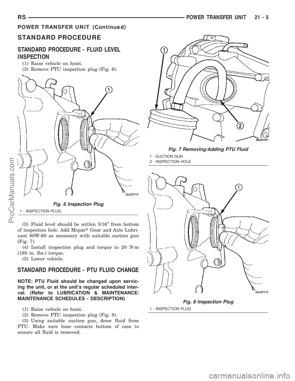
(1) Raise vehicle on hoist.
(2) Remove PTU inspection plug (Fig. 6).
(3) Fluid level should be within 3/16º from bottom
of inspection hole. Add MopartGear and Axle Lubri-
cant 80W-90 as necessary with suitable suction gun
(Fig. 7).
(4) Install inspection plug and torque to 20 N´m
(180 in. lbs.) torque.
(5) Lower vehicle.
STANDARD PROCEDURE - PTU FLUID CHANGE
NOTE: PTU Fluid should be changed upon servic-
ing the unit, or at the unit's regular scheduled inter-
val. (Refer to LUBRICATION & MAINTENANCE/
MAINTENANCE SCHEDULES - DESCRIPTION)
(1) Raise vehicle on hoist.
(2) Remove PTU inspection plug (Fig. 8).
(3) Using suitable suction gun, draw fluid from
PTU. Make sure hose contacts bottom of case to
ensure all fluid is removed.
Fig. 6 Inspection Plug
1 - INSPECTION PLUG
Fig. 7 Removing/Adding PTU Fluid
1 - SUCTION GUN
2 - INSPECTION HOLE
Fig. 8 Inspection Plug
1 - INSPECTION PLUG
RSPOWER TRANSFER UNIT21-5
POWER TRANSFER UNIT (Continued)
ProCarManuals.com
Page 1563 of 2399

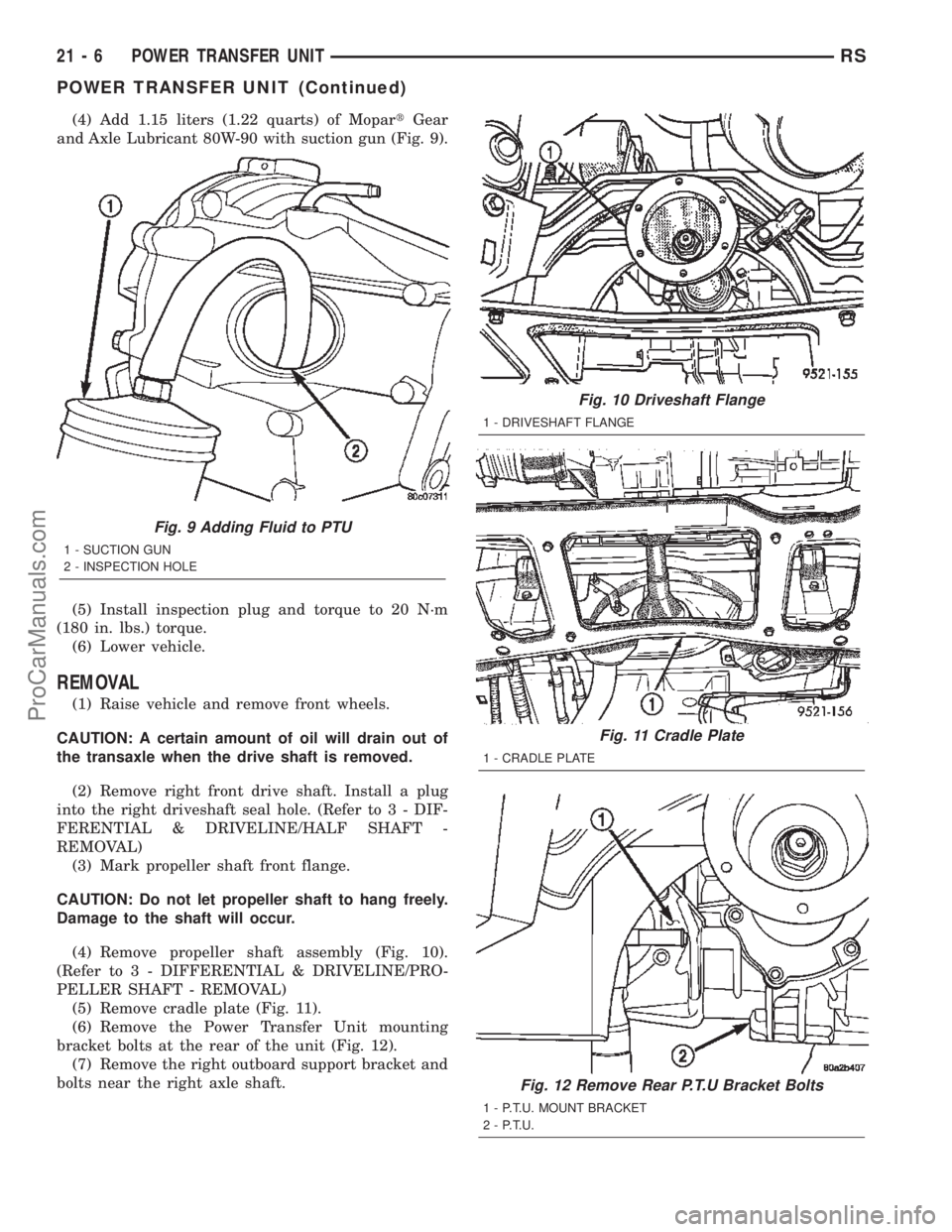
(4) Add 1.15 liters (1.22 quarts) of MopartGear
and Axle Lubricant 80W-90 with suction gun (Fig. 9).
(5) Install inspection plug and torque to 20 N´m
(180 in. lbs.) torque.
(6) Lower vehicle.
REMOVAL
(1) Raise vehicle and remove front wheels.
CAUTION: A certain amount of oil will drain out of
the transaxle when the drive shaft is removed.
(2) Remove right front drive shaft. Install a plug
into the right driveshaft seal hole. (Refer to 3 - DIF-
FERENTIAL & DRIVELINE/HALF SHAFT -
REMOVAL)
(3) Mark propeller shaft front flange.
CAUTION: Do not let propeller shaft to hang freely.
Damage to the shaft will occur.
(4) Remove propeller shaft assembly (Fig. 10).
(Refer to 3 - DIFFERENTIAL & DRIVELINE/PRO-
PELLER SHAFT - REMOVAL)
(5) Remove cradle plate (Fig. 11).
(6) Remove the Power Transfer Unit mounting
bracket bolts at the rear of the unit (Fig. 12).
(7) Remove the right outboard support bracket and
bolts near the right axle shaft.
Fig. 11 Cradle Plate
1 - CRADLE PLATE
Fig. 12 Remove Rear P.T.U Bracket Bolts
1 - P.T.U. MOUNT BRACKET
2 - P.T.U.
Fig. 9 Adding Fluid to PTU
1 - SUCTION GUN
2 - INSPECTION HOLE
Fig. 10 Driveshaft Flange
1 - DRIVESHAFT FLANGE
21 - 6 POWER TRANSFER UNITRS
POWER TRANSFER UNIT (Continued)
ProCarManuals.com
Page 1564 of 2399

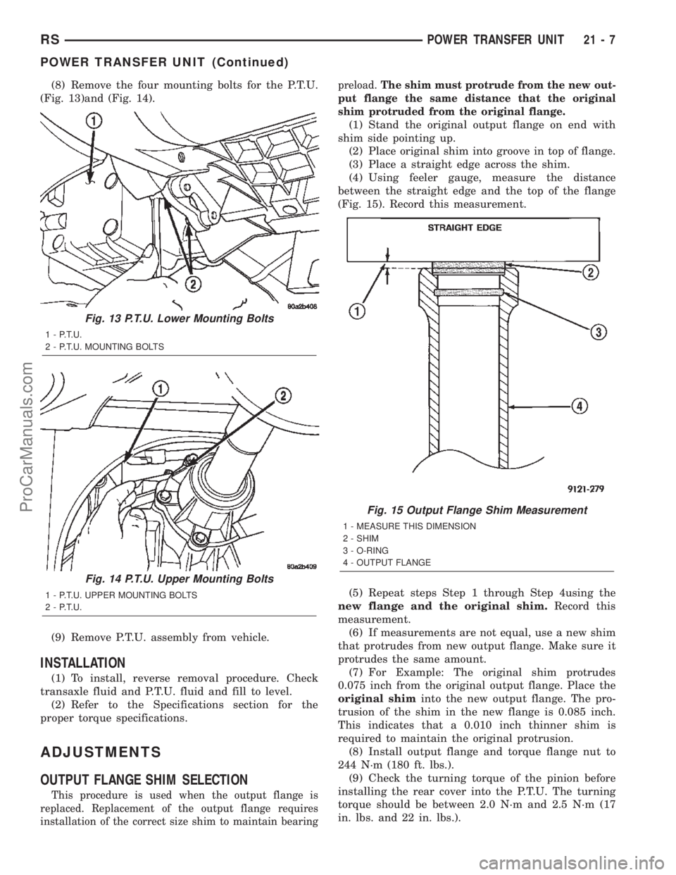
(8) Remove the four mounting bolts for the P.T.U.
(Fig. 13)and (Fig. 14).
(9) Remove P.T.U. assembly from vehicle.
INSTALLATION
(1) To install, reverse removal procedure. Check
transaxle fluid and P.T.U. fluid and fill to level.
(2) Refer to the Specifications section for the
proper torque specifications.
ADJUSTMENTS
OUTPUT FLANGE SHIM SELECTION
This procedure is used when the output flange is
replaced. Replacement of the output flange requires
installation of the correct size shim to maintain bearingpreload.The shim must protrude from the new out-
put flange the same distance that the original
shim protruded from the original flange.
(1) Stand the original output flange on end with
shim side pointing up.
(2) Place original shim into groove in top of flange.
(3) Place a straight edge across the shim.
(4) Using feeler gauge, measure the distance
between the straight edge and the top of the flange
(Fig. 15). Record this measurement.
(5) Repeat steps Step 1 through Step 4using the
new flange and the original shim.Record this
measurement.
(6) If measurements are not equal, use a new shim
that protrudes from new output flange. Make sure it
protrudes the same amount.
(7) For Example: The original shim protrudes
0.075 inch from the original output flange. Place the
original shiminto the new output flange. The pro-
trusion of the shim in the new flange is 0.085 inch.
This indicates that a 0.010 inch thinner shim is
required to maintain the original protrusion.
(8) Install output flange and torque flange nut to
244 N´m (180 ft. lbs.).
(9) Check the turning torque of the pinion before
installing the rear cover into the P.T.U. The turning
torque should be between 2.0 N´m and 2.5 N´m (17
in. lbs. and 22 in. lbs.).
Fig. 13 P.T.U. Lower Mounting Bolts
1 - P.T.U.
2 - P.T.U. MOUNTING BOLTS
Fig. 14 P.T.U. Upper Mounting Bolts
1 - P.T.U. UPPER MOUNTING BOLTS
2 - P.T.U.
Fig. 15 Output Flange Shim Measurement
1 - MEASURE THIS DIMENSION
2 - SHIM
3 - O-RING
4 - OUTPUT FLANGE
RSPOWER TRANSFER UNIT21-7
POWER TRANSFER UNIT (Continued)
ProCarManuals.com
Page 1565 of 2399

SPECIFICATIONS
TORQUE
DESCRIPTION...................TORQUE
End Cover................ 28N´m(250 in. lbs.)
Fill Plug.................. 27N´m(240 in. lbs.)
Flange Nut............... 162N´m(120 ft. lbs.)
Inspection Plug............ 20N´m(180 in. lbs.)
Rear Cover................ 28N´m(250 in. lbs.)
Ring Gear.................. 94N´m(70ft.lbs.)
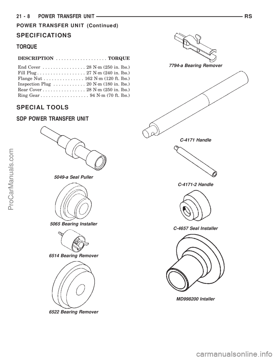
SPECIAL TOOLS
SDP POWER TRANSFER UNIT
5049-a Seal Puller
5065 Bearing Installer
6514 Bearing Remover
6522 Bearing Remover
7794-a Bearing Remover
C-4171 Handle
C-4171-2 Handle
C-4657 Seal Installer
MD998200 Intaller
21 - 8 POWER TRANSFER UNITRS
POWER TRANSFER UNIT (Continued)
ProCarManuals.com
Page 1566 of 2399

DIFFERENTIAL CARRIER SEAL
REMOVAL
The Power Transfer Unit must be removed from
the vehicle to replace this seal.
(1) Remove P.T.U. from vehicle.
(2) Use a pry bar to remove seal from retainer
plate (Fig. 16). Be careful not to damage seal journal
when removing seal.
INSTALLATION
The Power Transfer Unit must be removed from
the vehicle to replace this seal.
(1) Using a large socket, carefully install new seal.
The spring side of the seal must face the transaxle
differential.
(2) Reinstall the P.T.U. into the vehicle.
(3) Check and fill fluids as required.
END COVER BALL BEARING
REMOVAL
The end cover ball bearing can be removed and
installed without removing the Power Transfer Unit
from the vehicle. When replacing the bearing the output
seal must be removed to gain access to the bearing.
(1) Raise vehicle on hoist.
(2) Remove right front half shaft from vehicle.
(3) Remove output seal with a hammer and chisel
(Fig. 17).
Fig. 17 Output Seal Removal
1 - HAMMER
2 - CHISEL
3 - SEAL
4 - POWER TRANSFER UNIT
MD998334 Seal Installer
MD998346 Bearing Puller
Fig. 16 Transaxle Differential Carrier Seal
1 - TRANSAXLE CASE
2 - DIFFERENTIAL CARRIER SEAL
3 - RETAINER PLATE
RSPOWER TRANSFER UNIT21-9
POWER TRANSFER UNIT (Continued)
ProCarManuals.com
Page 1567 of 2399

(4) Remove bearing retaining snap ring (Fig. 18).
(5) Use bearing puller MD998346 to remove bear-
ing (Fig. 19).
INSTALLATION
The end cover ball bearing can be removed and
installed without removing the Power Transfer Unit
from the vehicle. When replacing the bearing the output
seal must be removed to gain access to the bearing.
CAUTION: When installing bearing, position the
bearing in place by hand square to the bore. Other-
wise, bearing and/or housing damage may occur
upon installation.(1) Use installer MD998200 and driver handle
C-4171 to install bearing (Fig. 20) into the housing.
(2) Install bearing retaining snap ring.
CAUTION: When installing bearing retaining snap
ring, be sure to index the snap ring so that the
snap ring does not cover bearing oil passage.
(3) Install new outer half shaft seal using
MD998334 seal installer (Fig. 21).Do not reuse the
old seal.
(4) Reinstall right front half shaft.
(5) Check and fill fluids as required.
Fig. 18 Bearing Snap Ring
1 - BEARING
2 - SNAP RING PLIERS
3 - BEARING SNAP RING
Fig. 19 Bearing Removal
1 - P.T.U. END COVER
2 - SPECIAL TOOL MD998346
Fig. 20 Bearing Installation
1 - SPECIAL TOOL MD998200
2 - SPECIAL C-4171
Fig. 21 Installing New Seal
1 - P.T.U. END COVER
2 - HAMMER
3 - SPECIAL TOOL MD998334
21 - 10 POWER TRANSFER UNITRS
END COVER BALL BEARING (Continued)
ProCarManuals.com
Page 1568 of 2399

END COVER SEAL
REMOVAL
The Power Transfer Unit must be removed from
the vehicle to perform this operation. (Refer to 21 -
TRANSMISSION/TRANSAXLE/POWER TRANSFER
UNIT - REMOVAL)
(1) Remove P.T.U. end cover bolts (Fig. 22).
(2) Gently tap on end cover ears with a hammer to
separate end cover from the case (Fig. 23).
(3) Clean and inspect sealer surfaces.
INSTALLATION
(1) Reinstall cover and tighten bolts to 28 N´m
(250 in. lbs.) in the sequence shown in (Fig. 24).
Retighten first bolt after all others are tight.
CAUTION: When end cover is installed be careful
not to damage the P.T.U. Input Shaft Cover Seal.
(2) Reinstall P.T.U. into vehicle.
(3) Check and fill fluids as required.
Fig. 22 P.T.U. End Cover Bolts
1 - POWER TRANSFER UNIT
2 - FILL PLUG
3 - END COVER
4 - OUTPUT SHAFT
Fig. 23 End Cover Removal
1 - END COVER EARS
2 - HAMMER
3 - POWER TRANSFER UNIT
Fig. 24 Bolt Tightening Sequence
RSPOWER TRANSFER UNIT21-11
ProCarManuals.com
Page 1569 of 2399

HALF SHAFT INNER SEAL
REMOVAL
The power transfer unit half shaft inner seal is the
smaller of the two seals located on the inside of the
end cover.
(1) Remove power transfer unit from the vehicle.
(2) Remove end cover bolts (Fig. 25).
(3) Tap on end cover ears to separate cover from
case (Fig. 26).
(4) Drive seal out with a hammer and small chisel
(Fig. 27).
Fig. 26 End Cover Removal
1 - END COVER EARS
2 - HAMMER
3 - POWER TRANSFER UNIT
Fig. 27 Seal Removal
1 - END COVER
2 - END COVER SEAL
3 - AXLE SHAFT SEAL
Fig. 25 End Cover Bolts
1 - POWER TRANSFER UNIT
2 - FILL PLUG
3 - END COVER
4 - OUTPUT SHAFT
21 - 12 POWER TRANSFER UNITRS
ProCarManuals.com
Page 1570 of 2399

INSTALLATION
The power transfer unit half shaft inner seal is the
smaller of the two seals located on the inside of the
end cover.
(1) Clean and inspect seal area.
(2) Install seal with a 1 1/16 inch socket (Fig. 28).
The seal must be installed with the spring side of the
seal facing end cover ball bearing. The seal will bot-
tom against a machined shoulder in the cover.
(3) Clean sealing surfaces of the end cover and
P.T.U. case. Apply a bead of MopartGasket Maker,
Loctite Gasket Eliminator No. 518 or equivalent.
(4) Place end cover onto P.T.U. case and install
bolts. Tighten bolts to 28 N´m (250 in. lbs.) in the
sequence shown in (Fig. 29). Retighten first bolt after
all other bolts are tight.
(5) Reinstall P.T.U. assembly.
(6) Check and fill fluids as required.
INPUT SHAFT COVER SEAL
REMOVAL
The power transfer unit input shaft cover seal is
the larger of the two seals located on the inside of
the end cover. The differential bearing cup must be
removed to service this seal.
(1) Remove P.T.U. end cover bolts (Fig. 30).
Fig. 28 Seal Installation
1 - END COVER
2 - SOCKET
3 - HAMMER
Fig. 29 Bolt Tightening Sequence
Fig. 30 P.T.U. End Cover Bolts
1 - POWER TRANSFER UNIT
2 - FILL PLUG
3 - END COVER
4 - OUTPUT SHAFT
RSPOWER TRANSFER UNIT21-13
HALF SHAFT INNER SEAL (Continued)
ProCarManuals.com